SVN revision 100
    - improve motor control
    - check EEPROM layout on startup

From this version EEPROM layout is fixed. This mean that you can enable
"preserve EEPROM" fuse and your setting can be saved.

Change EEPROM layout case is tested on code. You will see "EEPr" on LCD
after restart, startup is blocked. With empty EEPROM you will see same
message.

*I don't know any missing functionality or bug at this moment.*

Permanet problem is missing documentation generated from sources. We
need it to document "magic indexes" on setting (Gxx and Sxxxx commands)
or watches (Txx command)

Changelog:
http://openhr20.svn.sourceforge.net/viewvc/openhr20/trunk/source/changes.txt
Known problem for Rev100:
After change of PID constants you must change wanted temperature.
Problem is teoretical internal value overload. I never saw this problem,
but I found it on code review.
@jdobry:
very busy weekend! gonna try your latest release tomorrow when i have a
JTAG-adapter again.
gonna give you feedback about how the firmware works.
will try to get familiar with the general firmware architecture then,
for example questions like "how can i issue a task evry sixty seconds"
which shall be the RFM's staus broadcast in sooner future...
so long!
@ Mario Fischer:

execute task every second:
add it into "if (task & TASK_RTC)" section on main.c

execute it every 60 second have many choices
- use own counter inside "if (task & TASK_RTC)" (worst)
- same section as before, but inside new "if (minute)" condition
(better)
- same section, add condition "if (RTC_GetSecond() ==
config.network_addreess)" (best)

For interrupt from RFM you must add code inside "ISR (TIMER0_OVF_vect)"
and set "task |=TASK_RFM12" inside. Make code inside interrupt small as
is possible and move real functionality inside main.c "if (task &
TASK_RFM12) task&=~TASK_RFM12; ....."

f you have some code sniplets, please contact me by email. It have big
priority for me at this moment.
Hi Jdobri!
(what is your first name? I dont know if "Hi Jdobri" is correct ;)

ok, ive downloaded the OpenHR20-rev 103 and started to play with it...
I will try to integrate a RFM status sender for first approach.
I can say now, i will have to make changes in several files. For example
main.c in
  if (task & TASK_RTC) { ... if (RTC_GetSecond() == g_RFM_devaddr) ...
and so on.
I would try to encapsulate all RFM-stuff  in #ifdef RFM-blocks, so a
project-fork wouldnt be neccesary.
But im not sure if i can guarantee that it will be possible to
distinguish RFM and notRFM-code clearly in all future.
So, what do you want to do?
Can you give me an SVN-Account for the project? Im sure you will be
anoyed very soon if i start to mail you my code all the time...
So, tell me your plans!
Greets from Munich,
Mario

PS: First Request: I'd like to have the global variable uint8_t
g_RFM_devaddr to be adjustable by menu (1-254, others reserved for
broadcast or future usage) and storable in EEPROM.  Since youre master
of the menue it shouldnt be too difficult? ;)
Plan is keep latest STABLE version in main trunk and create branch for
next development. By this way we can made anything include crazy ideas.

You don't need change anything on menu. Simple add line into eeprom.h
structure config_t and line into ee_config array. Don't forget change
eeprom layout map version to something for development (exaple #define
EE_LAYOUT (0xd0) ).
You can read it by config.g_RFM_devaddr and change it by service menu
(long press all buttons -select configuration press PROG change value
and press PROG)
Question about the Config-Menue:

Did i get this right?
I can edit the Variables in eeprom.h via:
1. Pushing [AUTOMANU + TEMPSUNMOON + PROG] for 3 seconds.
2. Then display shows XX:YY, ourbar shows all bars, XX blinks
3. with the scroller i select variable number XX, then i push [PROG],
then YY blinks and i can set XX's value (within the range given in
eeprom.h).

now its getting unclear: it looks like if i push [PROG] i'm back in
selecting a XX again. is the other value now stored? or how can i cancel
it (i guess via AUTOMANU] )? and what's happening if i push
[TEMPSUNMOON] ? hourbar except one bar blinks, scroller selects a
horbar, XX:YY shows thigs i dont understand...
[AUTOMANU] always exits eeprom-edit-mode?

regards!
Feature Request:

in normal mode, [TEMPSUNMOON] shows current temp, valvepos, RTCtime,
default display. i think that the RTCdate would also be interesting for
a common user.

regards!
Service mode:

1. Pushing [AUTOMANU + TEMPSUNMOON + PROG] for 3 seconds.
2. Then display shows XX:YY, ourbar shows all bars, XX blinks
3. with the scroller i select variable number XX, then i push [PROG],
then YY blinks and i can set XX's value (within the range given in
eeprom.h)
4. press PROG save selected value and go to step 2

any where on service menu:
AUTO - escape service menu without save
C - change service menu from EEPROM setting <-> watched variables and
back

Watched variables - see to watch.c. In this mode ALL segments are on,
except 16-bit hex value on numbers and except one blinking segment on
hourbar. Blinking segment indicate with values is on view. Ekvivalent
COM command is "Txx<enter>"
RFM Pin wiring:

you wired yor RFM like ths:

rfm_sck  = atmega169_pf1 //solder direct to atmega :-(
rfm_sdi  = atmega169_pf0 //solder direct to atmega :-(
rfm_nsel = atmega169_pa3 //solder direct to atmega :-(
rfm_sdo  = atmega169_pe6 //crop via on backside of PCB as shown in
picture
rfm_nirq = open

as discussed yesterday, rfm_nirq = open, because rfm_sdo can serve as
irq-notifier. we will read the sdo-state after we drove rfm_nsel low.
i assume that it will be high when the rfm is still busy sending, and
edging low when ready (irq-event like "byte sent over radio in txmode or
fifo-filled in rxmode). we need to clarify when we go into the sleep
mode then and how we wake up/resume in main-loop.

... ive looked once again on pCB and schematic, it really looks like
that there is no other way than soldering 3 pins directly to the
atmega169? this is really a VERY sophisticated soldering job.
is it possible to disable the atmega's jtag-interface during runtime
only?
that would make the soldering job really easy, we could even wire the
RFM externally so that people dont have to open the HR20. of course,
disabling jtag via fuses requires a working bootloader and is (as far as
i know) not reversible...
are there any alternatives than soldering to those tiny nasty
atmega-pins?
RFM Wake up will be done by interrupt PCINT9 and setting task|=TASK_RFM.
When we process this event, we must to do task&=~TASK_RFM and it will
allow sleep in main loop.

Connection RFM to ATmega we have only by 2 ways and both is similar, can
be changed by compile option  (different is only signal names).

1) connect wire directly to ATMEGA as in my pictures

2) use JTAG pins. JTAG is possible disable in runtime and it is also
possible to use it for programming but for it we must hold reset signal.
It is not problem. But it is no possible share this pins for debug.
Therefore it can be possible way for end-user, not for development.
Benefit is that it can be connected outside without open HR20.

JTAG disable by fuses is not reversible by JTAG interface because it is
disconnected. But this configuration can be changed later in runtime and
we can reenable it by hold reset signal.
Hi,

disable JTAG:
i have googled it but couldnt find something useful. the only rumor i
read was that "disabling JTAG at runtime doesnt mean setting the
DisableJtagFuse" which would be very good because this could really
cause trouble when the frmware crashes and cant execute any "ReEnable
the JtagFuse again" command.
do you have a sniplet how to use JTAG-Pins as IOpins at runtime without
messing with the fuses?

I would like to get this working soon, because i cant solder my RFM to
the Atmega's pins directly - these ones are too small for me :(

Idea:
Is a "mixed version" of RFM wiring (JATG vs. internal pins) possible as
well?
That eans using JTAGpins<=>RFM except RFM's nSEL, which we wire to PE6 -
that is the pin that is reachable by cropped via on PCB, so its possible
to solder.
Idea:
In JTAGmode PE6 is HighZ => RFM's nSEL is not tied to GND and not
SELected => RFM's other pins should be HighZ (gotta look that up...)
which means the RFM shouldnt disturb the Programming Traffic between
JTAGprogrammer and Atmega => no need to unplug the RFM when JTAGging.

Security:
I checked in a security.c module. mainly uses XTEA (yet written in C)
for en/decryption in cipher feedback mode. has the nice side effect,
that we dont need the code for XTEA-decipher (see
http://en.wikipedia.org/wiki/Block_cipher_modes_of_operation#Cipher_feedback_.28CFB.29
).
i also abused the XTEA-code for a hash function in for
chall-resp-authentication. code not yet tested but function interface
shouldnt change.
Disable JTAG only for runtime: write one to the JTD bit in MCUCSR.
Datasheet chapter 9.8.7

We don't have any reason to mixed version of wiring. In this case we
will lost JTAG and we must solder inside HR20. It is not possible share
one pin on JTAG interface. JTAG can be completly disabled, nothing more.

Problem with share JTAG pins it not programing, but debug.

Security:

Yes, we can use XTEA encryptor on feedback mode to generate key to
encrypt data. see to
https://roulette.das-labor.org/trac/browser/microcontroller-2/QPort/qport.c

But it have problem. Cipher on RX and TX side must by synchronized
otherwise is not possible to decrypt data. On wirelless is usual lost
same data, therefore in this case we can lost synchronization. It is
complication.
Hi!

Disable JTAG: ok will check that register in the atmegas manual. thanks!
mixed wiring: yes youre right, JTAG-firmwareupload is possible (if RFM's
pins are really HighZ when nSEL=High) but debugging is not possible.
i think it's ok as it is - you can use your directly soldered pins and i
the JTAG (and cant JTAGdebug, but i dont need that often).
its just pin definitions (see my rfm code its completely adjustable with
some #defines).

security:
dont worry about the syncing! the CFB resets with every sent-out
datagram again. it is just feedbacking within one datagram. otherwise it
would be impossible for a receiver who was offline for several datagrams
to resynchronize. id suggest this data format:

payload = [rand,currtemp,wantedtemp,valepos]
enc_payload = security_encrypt(payload)
packet_nocrc = [deviceID,enc_payload]
length = sizeof(packet_nocrc) + 1 // + 1 for crc
crc= crc8([length,packet_nocrc])
rfm_send([length,packet_nocrc,crc])

if you want to you can encrypt the deviceID as well. but point is that
we must use additional crc for checking air damage (crc is better for
that than any hashes). rand is a random number that "salts" our
security_encrypt => equal payload (except different randoms) will
produce completely different enc_payloads. so its not possible to create
a codebook. this salting rand could be also used for chall-resp-authes.
i was just thinking ...
do we need a hash-function at all?
if the master authenticates via sending the rand value back within an
encrypted message, then the master has proofen that he knows the shared
key.

so scenario:
1. hr20 status broadcast every minute
(length,devID,encrypted[rand,currtemp,wantedtemp,valepos],crc)

2. master receives that, decrypts packet and has rand in plain format.
when master wnts to send a command to the HR20 he sends (within one
second after HR20's broadcast):
(length,devID,encrypted[rand,CommandTotheHR20],crc)

3. HR20 unpacks that datagram, checks rand, and if it is equal to the
rand from (1.), CommandTotheHR20 is executed

4. HR20 sends back
(length,devID,encrypted[ResultCommandTotheHR20],crc)

5. HR20 listens another second for a further command (again with rand
included), and if not occuring, HR20 waits a minute till (1.)

what do you think? rand is encrypted in all air messages and different
in every (1.)
@Mario Fischer:

Your proposal looks good. I would like want only this modifications:

- use upper bit of length or devID to indicate HR20->master or
master->HR20 communication (benefit: we can reject unwanted packes
before decoding)

- remove step 5. After step 4 we can go back to 2. It have benefit that
we don't need keep receiver alive 1 second. Timeout can be smaller (max
aprox 100ms)

- use SYNC byte before communication, RFM support it in HW. It can
filter possible noise from others wireless comunications. I am sure that
you know this RFM feature but you forget write it in proposal.


And some technical notes:

- If you wan't, I can integrate RFM SPI layer into current code
(interrupts, create task etc.)

- It will be nice reuse/modify current COM code (same commands, same
results).
-- We can modify numbers in commands/responses to "compressed" version
(not use hex coding but raw format)
-- wireles layer will encapsulate COM packets and manage encryption.
-- it not need \n as command termination char (size of wirelles packet
is known)
We need hash or XTEA feedback hash.
Without this it is easy decrypt ((packets) xor (fixed key)).

Therefore we cant restart hash function for each "status" packed from
HR20. It is just variant of fixed key.

What we can to do:

step 2 on master: we must reply to HR20 with command or empty packed
(length,devID,encrypted[rand],crc)
step 2 on HR20: after success on receive calculate next step of hash
function to generate packed key

What can happen (success):

-step 1: HR20 will transmit packet with packet key generated from hash
(PK1)

-step 1: master receive it and decrypt it with PK1

-step 2: master transmit packet with PK1 and calculate PK2

-step 2: HR20 receive packet, decode it by PK1 and calculate PK2

What can happen  next (fail):

-step 3: HR20 will transmit packet with packet key generated from hash
step 2 (PK2)

-step 3: master receive it and decrypt it with PK2

-step 4: master transmit packet with PK2 and calculate PK3

-step 4: HR20 fail to receive packet, PK3 is NOT calculated

-step 5: HR20 will transmit packet with PK2

-step 5: master receive it and try to decrypt it with PK3 it fail, but
will be successfuly decrypted with PK2

-step 6: master transmit packet with PK2 ( calculation of PK3 not
needed)

-step 6: HR20 receive packet, decode it by PK3 and calculate PK3

What can happen  next (another fail):

-step 7: HR20 will transmit packet with PK3

-step 7: master fail to receive

-step 8: HR20 will transmit status packet next minute with PK3

-step 8: master receive it and decrypt it with PK3

-step 9: master transmit packet with PK3 and calculate PK4

-step 9: HR20 receive packet, decode it by PK3 and calculate PK3


......

I hope that it is clear. PK numbers is not significnt
(PK[n+1]=hash(PK[n])). But we need to solve resync after HR20 or master
is restarted (some initial fixed key)
I thinking.

(some initial fixed key) must not be fixed. It can be fixed part +
something from user for every init.

In this case, user must read one or two bytes from master and enter it
manualy into HR20.

It just only idea .....
Hi!

well, SPI is not the problem, the SPI-function itself is very very fast,
Problem is as discussed the waiting between SPI and SPI.
if you could write some code where i could integrate something, would be
fine!

Air-Protocol: In my implementation i had an additional byte "flags"
with several useful values (contains ReceiverAddress, LoBatt,
IsEncrypted...).
I left that away in my sketch but a concrete implementation will contain
sth like that.

"1 second" is of course a too long time period. we could shorten it.

Dont let us mix up all those SYNCS: you meant the sync-pattern the RFM
sniffs to
(and when he detects it he loads everything following into the RxFIFO) -
Yes the Sender must Send Sync and 0xAA0xAA-Preamble before (and trailing
0xAA as well!).
i also left that away in the sketch for keeping it simple.

Commands: yes com-proto-reuse would be nice but ascii-over-air makes
datagrams too long -
too dangerus. we must compress/binarize it somehow. also sending
multiple commands
without delimiter if fixed length in one packet is good - then we can
leave away the relisten for one second
from step 5.
Ok, gonna handle your latest post with security leak now...
Hi
i was quite busy in the last days, so i had no time to answer.
I don't have much time, but my business is embedded security.
Also i am often in das-labor.org, which is located near my home
(about 5 minutes walk)
Mario Fischer wrote:
> do we need a hash-function at all?> if the master authenticates via sending the rand value back within an> encrypted message, then the master has proofen that he knows the shared> key.
Encryption != Authentication.
I will show you the error in your proposal:
An Attacker would receive from HR20
> (length,devID,encrypted[rand,currtemp,wantedtemp,valepos],crc)
He is not able to dencrypt this, but the master will anser e.g.:
> (length,devID,encrypted[rand,CommandTemp=20],crc)
Note: the attacker is not able to dencrypt this.
But he can se, which part of both encrypted parts is the same.
So he knows enc(rand).
Now what the attacker can do some days later:
The HR20 sends:
> (length,devID,encrypted[randnew,currtemp,wantedtemp,valepos],crc)
The attacker can replay the old command:
> (length,devID,encrypted[randnew,CommandTemp=20],crc)
There are many ways to avoid this. This can be done by using different
keys for encryption on both sides (key_H2M: HR20=enc Master=dec,
key_M2H: Master=enc HR20=dec).
Better it would be to use a MAC like CMAC[1], which can be done with
the Block-Cipher.
If you have some requirements, i can assist you in designing the
secutity functionality.
For cipher i would consider to think about using XTEA. Alternatives are
AES (about 1000 Words) or (better) PRESENT [2]. PRESENT is optimized
for very small hardware, but I think it should also be quite small on
the AVR. Nevertheless also XTEA would be OK.
[1]http://en.wikipedia.org/wiki/CMAC
[2]http://crypto.rub.de/imperia/md/content/texte/publications/conferences/present_ches2007.pdf
Hi guys,

ok im also thinking about the auth&encrypt stuff again.
some facts:
- we already decided for XTEA, seems secure "enough" (yes sounds sleazy
but code must be short => XTEA is excellent trade off)
- and we cant use long keys, digests or random numbers over air since
radio packets MUST be short. the counterpart to short key is that our
"slave" only accepts auth-tries every minute at all, so we must primary
defend offline-attacks.
- the amount of packet-ping-pong between auth/chal/comd/reply must be
short for battery.
- we can not use any circulating P[n] -> P[n+1] tokens because master or
slave can be offline for a while. Token or n might get lost.
- yes encryption alone doesnt replace auth or protects from playback.

let me ask you guys again about the leak here, i still dont see it:

1. Slave sends (simplified):
Encrypt( [rand1,statusinfo] )

2. Master sends
Encrypt( [rand2,rand1,command] )

3. Slave sends (if rand1 was recognized)
Encrypt( [rand3,rand2,result] )

i agree with dario that attacker could see enc(rand).
so i putted a rand2 on start of message in 2 which will scramble all the
rest of the packet (->CFB mode) (lesson learnd ;)
beside, even if the attacker could catch a rand/enc(rand)-pair, then he
couldnt offline-calc the key: rand is shorter than the key so many keys
would produce the same rand.
and the attacker would have to run thru the key-span (big) and not thru
the random-span (small).

ok, whats the weakness in this protocol?
we have lots of power/packetsize/battery/pingpong-constraints guys, we
must keep it simple!
Another thing:

to distribute the keys in HR20 (Slaves) and Master
we should think about the possible solutions:

a) Keys are compiled in the Software
b) Keys in EEPROM
   - can be entered using serial interface
   - can be entered using Service mode

I would prefer to enter the keys in EEPROM.
For maxium Security the key must at least 64 Bit,
better 80 Bit. So it would consume 8 to 10 Bytes
in Configuration Memory.

A key exchange between Master and Slave is only
possible, when we would use asymmetric functions
like Diffie-Hellman. All other key exchanges are
not secure, when they all use the same (master)key
for all HR20s.

Dario
@dario:

key distribution: already done. its stored in eeprom and
changeable via HR20's LCD/Button/Wheel-interface.
Jiri did a great job with his extensible interface!
=> key distribution is no problem.
i coded the keysize variable length. if shorter than xtea-key it will be
padded (no user wants to enter a 16-byte key in every HR20 so i think
padding is ok. it's not home-banking ;)

i think i see now the point you wanted to show with your "a few days
later":
but thats a tradeoff we have to accept: if the rand is only one or two
bytes long than it will some day repeat. again a trade-off for
short-radio-packets.
but even if the attacker has an old packet with matching rand. then he
could inject a packet of which he doesnt know what it will do.
@dario:
if you are interested, you can look at the current state-of-the-code in
the

http://openhr20.svn.sourceforge.net/viewvc/openhr20/rfmsrc/

branch of the project. new files are rfm.* and security.*
security is as mentioned still in a draft state.
i will think about the "do we need hash function if we have
symetric-cfb-encryption?" again... i still think we dont need hash
because cfb-enc kills all plain-cipher-pair-recognition-possibillities
...
@Dario C:

You are right.

For clarify: If attacker have 2 encrypted data with some KEY and know
information that it contain common par of source data (rand) it is
security hole. Attacker can easier calculate key. And from PK(n) can
calculate PK(n+m) (with hash it is simple, with XTEA in feedbak it can
be nightmare). (Example in history is repeat random part of KEY in
encrypted communication used at ENIGMA - decrypted in Poland 1934 by
Rejevski)

we must have something like protocol specification before coding. From
my side exist only small chance to do something till Xmas (I am quite
busy).

Therefore we have time to thinking about it.
Mario Fischer wrote:
> let me ask you guys again about the leak here, i still dont see it:> 1. Slave sends (simplified):> Encrypt( [rand1,statusinfo] )> 2. Master sends> Encrypt( [rand2,rand1,command] )> 3. Slave sends (if rand1 was recognized)> Encrypt( [rand3,rand2,result] )
I think you gonne send many data, which is not needed.
You saied, that radio packets MUST be short.
1. Keysize does not affect packetsize.
2. How long would your random mumbers be?
3. I think there are many better solutions,
when we think a bit about it.
4. Security can be added later, you can implement
2 Dummy functions on each side generate_msg and
verify_msg, which can be filled later.
I have to think about it, but for me it seems to be
a "Homebrewn" sollution which is not the best we
can have.
Also XTEA is very old, PRESENT is much newer and provides
better security. I think it should not be bigger than XTEA;
> we have lots of power/packetsize/battery/pingpong-constraints> guys, we must keep it simple!
I Agree, but we should keep it smart, and simple.
And in your proposal i see that many random numbers are send,
which leads in big overhead, at least double rate
1
Overhead
2
============
3
Security
Let me ask a Question, befor i start to think about
a better solution:

Who is the Master?
- How much memory
- What computational power

If the HR20 shall talk to each other without a master,
than we have a problem. If not i think that the Master
can recover missing sync information, so that we don't
need to send the useless rand information. We would
need to send some additional Bits (32 to 80) for
authentication.

But I have to think about it.

Dario
Mario: "we can not use any circulating P[n] -> P[n+1]"

NOT we can't do it like this. It big secutity hole. When one of station
is offline it is not problem. See to my comments from 09.12.2008 23:48

But Dario is right, we cant repeat same data with 2 packet with same
key.
Mario Fischer wrote:
> i think i see now the point you wanted to show with your "a few days> later":
No, when a few days later another rand (randnew) is send, i can replay
the old command, which was the response to the old rand.
I think when we use 1 or 2 Byte rands, than it is better to use
no security at all, because it can be very easy broken.
But I think by adding 4 Byte additional data to the frame, than
we can get the security of 4*8=32 Bit and by adding 8 Byte we have
64 Bit security.
But i have to think about it, i will write a purposal document for
security when i am not so busy (during the holidays).
Dario
@dario

- i diddnt know PRESENT but a first google shows me that it has s-boxes
... thats way to expensive!
- xtea is old, but look at known weaknes of it ...
- are there any other well-known and analyzed algorithms as short as
xtea?
- no hr20-hr20 communication.
- only hr20->master->hr20 talks
- master ... dont know... a linux-box, a atmega32, ... but doesnt play a
role: the computing-power-bottleneck is the HR20.
- random number lengths: i would guess 1 or 2 bytes. i know its short.
but be realistic: anyance over a shorter living battery from long radio
packets is more likely than someone who records about 256 or 65536
commands (there is NOT a command EVERY minute!)

> But Dario is right, we cant repeat same data with 2 packet with same
key.

do you really want some session-key-generation-protocol? this requires
lots of traffic!
the whole send encrypted random vice and versa is not my idea. i thik
its occuring similar in kerberos (let me look it up) but its not my
invention...
Dario C:

I know about PRESENT but it is too expensive

PRESENT - AVR C implementation  - 1514 bytes of flash and 256bytes in
RAM

XTEA - AVR C implementation - 754bytes of flash, 0 bytes in RAM

XTEA - AVR ASM implementation - 504bytes of flash 0 bytes in RAM

source: http://www.das-labor.org/wiki/Crypto-avr-lib/en

We have aprox 3kB of free flash in current SW. Save every byte is fine.
Mario: you dont need any session-key-generation-protocol

It is simple. You have key for packet (PK) , and master key (MK)

And you ca to do:

//have function encrypt(data,key)
PK(n+1) = encrypt (PK(n), MK);

You can calculate it on both sides withou any
session-key-generation-protocol

You must only keep synchronization you cant decrypt PK(324245) encrypted
packet by PK(6756324)
Jiri: im still trying to understand your post from 09.12.2008 23:48 -
could you summarize that all a little please?

how many transmissions each minute?
what is transmitted in every packet?

and im still insisting, that after one minute everything must be reset.
there may be no references to any randoms or packetkeys that occured one
minute before.
master or slave can be offline always and the other doesnt know it!
so after one minute, everything has to start from scratch.

so long guys, i fall asleep now!
Mario Fischer wrote:
> - i diddnt know PRESENT but a first google shows me that it has s-boxes> ... thats way to expensive!
Yes one 4Bit-to-4Bit S-Box = 16 Byte.
> - random number lengths: i would guess 1 or 2 bytes. i know its short.> but be realistic: anyance over a shorter living battery from long radio> packets is more likely than someone who records about 256 or 65536> commands (there is NOT a command EVERY minute!)
But when we use 1 Byte an attacker needs 128 tries for the chance
of 50% to change the next random number and so to destroy any
further communication.
The attack is on: Encrypt( [rand2,rand1,command] )
The attacker would send some random data, to the HR20 as response.
When the HR20 decrypts this data and the second byte is accidently
rand1 (which is 50% for 128 Tries), it would save rand2 as new value,
which the master (and the attacker) does not know.
=> After that no further communication is possible.
I will think about a solution to provide security with additional
4 to 8 Byte each packet.
> do you really want some session-key-generation-protocol? this requires> lots of traffic!
I asked how the keys will be distributed, as they are in the
EEPROM this is not an issue anymore.
im almost in bed, but let me shot comment
> destroy any further communication.

thats why i insist on "reset everything every minute"
destroy any further communication would otherwise also be possible if
only one minute's session fails - then both wouldnt be synced.

let me clarify: all my rand0,rand1,2,3.... are diced every minute from
new!

in general, it is always possible that an attacker records a packet and
playbacks it every minute - after latest 256 or 65536 minutes it will be
considered as valid.
i can accept the threatof such an scenario, since long packets are very
battery-consuming. i measured the rfm's current consumption during
sending with shunt+osci, thats why 4byte-randoms are too expensive to
me.
Mario:
how many transmissions each minute?
- not change from your proposal

what is transmitted in every packet?
- not change from your proposal

You don't need sedn any aditional data for key change. Becasuse  you can
calculate PK(n+1) from PK(n) if you know master key (stored in EEPROM)

You only must try for decryption use PK(n) and when you have not success
PK(n-1). If you have not success with PK(n), it mean that one or more
packets was lost and second side not change PK
Hi guys,

i followed this and the other threads a long time.

what i read out since now is that in between there is an open firmware
available.  now, you want to get/send data from/to the HR20 via a rfm
module. but why should this be encrypted? the WHY is here missing. since
now i thought it should be an OPEN firmware? Maybe i didnt understand a
block or i missed one?

cu,
olly...
Open: The firmware's source code including encryption algorithms is open
source. The encryption key is selectable by the user.

Encrypted radio Traffic is to protect your HR20-valves from unauthorized
people to control your room temperature or even detect from outside that
your room temperature is cold (so you might not be at home and they
could break in).

No fundamental discussions about "who is interested in controlling my
valves?" please! Protecting the system is not much code but always worth
some thoughts about!
Guys, one Question:
If our radio packets are always smaller than a XTEA blocksize, then the
whole CFB or OFB modes dont make sense:

Because in both modes, the first plainblock is just XORed with
XTEAencrypt(Key,Initvector).
This means that the whole plainblock is just XORed with a constant
bitpattern.
This would mean that even one captured Plain/Cipher-Pair would disclose
this constant Key.
So i would suggest CBC mode or no modes at all if all radio telegrams
are < 17 bytes (what i would recommend). on the other hand, telegrams
smaller than 16 bytes would have to be blown up to a XTEA-block.
Hi Jiri and OpenHR20-Team,
today I managed to make the HR20 send a radio frame with the RFM12
Module connected to the outside-accessible JTAG-Pins and PE2.
Well, almost -
I saw that quite often bytes are swallowed. For testing i let the HR20
send a bigger frame with increasing bytes
<preamble> <fifo start patt> 0x01, 0x02, ... 0x13 <dummy byte>

on the receiver side i saw things like
0x01 0x02 .. 0x04 0x50 0x60 ...
                    ^^

in other words, sporadically swallowed bytes or nibbles and some noise.
Im quite sure its not the receiver which is swallowing the bytes, this
device im using for long time and it always worked.
I also looked at with the scope to the distances between the
SPI-16bit-Trains, their distances were not equal!
I suspect rather that the SDO line indicates the "ready to send next
byte" (TX flow control) event to early, multiple times, ... or the
InterruptRoutine sensing for SDO Edges somehow raises the "send next
byte" codition too often or to early ...
Im not sure where the problem is. In my other applications, I flow
controlled always with the IRQ line, which works fine.
The RFM datasheet tells us that the SDO line also is usamble for flow
control, so we want to use this line (to save IOports).
For test purpose i will connect the RFM's IRQ to the ATmegas IRQ (PE6)
and check wheather this is the cause of the stumbling TX flow control.
But im not sure, could be many sources
SDO not relieable for Flow Control,
OpenHR20's PinCHange-ISR has an error
main-task-loop has an error.

Updates will follow ...
Hi,

I have a problem with my HR20E ordered at Conrad, it is the same problem
at all three of them:

They work fine in the Full-stroke mode. Yet, in the default-stroke mode,
radiators stay cold after about three days, even though the HR20E shows
a higher target-temperature. Removing the Rondostat and turning the blue
wheel by hand, the radiators get warm. When it gets above the
target-temperature, they are turned of properly and the Rondostat will
work fine for another three days or so.

This should not be a battery problem. The batteries are new and
brand-products, and the Rondostat makes no sign of having a power
shortage at any point. It should neither be a problem with the valves
since the radiators get warm when I turn the blue wheel by my self, and
since the problem does not occur in the full-stroke mode.

It seems to me, that after a few days in the default-stroke mode, the
Rondostat does not know anymore at which position it is, and does not
open the valve as it thinks the valve is already open.

Does anyone know a solution for this? In the Full-stroke mode, the
temperature deviations from the target-temperature are too high since my
radiators heat up very fast.

Thanks for your answers,

Robert
Hi

just managed to flash the first HR20. I used the Atmel Eval Boarad from
Pollin modified according to the Evertool LIGHT by Rainer Rakow.
Starting test now...

Is there any readable user manual or anyone working on it?

Robert, i ordered 8 HR20 from CONRAD and had no problems found. Did you
rewind the blue weel before installing the head? But carefull - its easy
to overwind!

I read about similar problems in another thread - in one case some coins
helped to reduce the distance between the nozzle of the valve and the
regulator pin.

Frank
@Robert:

I have 5 valves (exacly same) and only one of them have same broblem. It
not depend to HR20 unit, but on valve. With original SW you can only use
"full stroke" mode. You not able change anything or discover it.

And it is one of reason why I wrote another SW for HR20. In my case it
is solved.

@Mario Fischer:
I will try discover where it problem tomorow.
@jdobry:
meanwhile i looked a little closer at the distances of the
SPI-RFM-SendByte-Commands. I let every time such a write-command occured
toggle a pin and looked at it with the osci, and their distances looked
good.
im not sure if the problem is in the receiver. it might have been false
what i wrote in my last posting, sorry. but i will test it a little more
today and know more.

Full-Stroke-Issue:
I have a general question:
The HR20's Manual sais, that the HR20 knows a Default and a
Full-Stroke-Mode of turning the Valves off and on. When coming out of
the Box, HR20 is in Default-Mode. What is the use of this so called
"Default-Mode"?
I thought, the HR20 works like this:
* When HR20 is screwed on Valve (detected by switch), then ...
* HR20 turns on Motor to rotate left,
  until the light eye doesnt pulse any more (gearwheels block)
* Set a lighteye_pulsecounter=0
* Turn on Motor to rotate right,
  until light eye doesnt pulse anymore and count pulses in between.
  Then set lighteye_pulsesmax = lighteye_pulsecounter
* Now the mechanic is in a defined state (valve=100%)
  and we know that
  [Valve0% .. Valve100%] <=proportional=> [0 .. lighteye_pulsesmax]
  Which this knowledge and pulsecounting,
  we can put the Valve to any % we want.

I guess this is the full-stroke mode. So, whats the Default-Mode?
What would be the meaning/benefit of it?
Whats the use of having a water tap that you dont open or close
completely?
@Jiri:
My Description of the Valve-Calibration - is this like your Calibration
Algorithm? And if so, how do the described Phases correspondend with
your "C-1" "C-2" "C-3" Calibration Messages?
Your Code looks like if there is a "Manual Calibration" and a "Auto
Calibration", but i couldnt find out when which mode is driven, and
what's Manual at the manual Calibration.
And what are you working with PWM with the Motor?
I thought only the direction of the Motor is important when Setting a
Valve-Position (which is selected by the 4 H-Bridge Transistors next to
the Motor i guess), but why is Motorspeed interesting?

Could you tell us some words about these things? We will need this text
snipplet later probably for the User Documentation.
Thanks!
Mario
Hi at all,

today I finished the first (Christmas) release V 0.2.2.25740 for the
openHR20 Suite which allows comfortable managing of the module settings.

Since I was very busy adding functionality, not all things are well done
and some problems may arise (if you find some, please report).

The SW is based on .NET Framework 3.5 and uses WPF instead of Windows
Forms windowing. It was developed on a Vista notebook but should also
work with XP. The 3.5 .NET Framework is not contained in the installer.
If you don't have it already installed, you must obtain it from MS.
Basically WPF GUIs are very pale but the design can be changes
tremendously. If anybody here has Expression Blend and has experience
with good design, may contact me.

Only one hardware platform was used, so I can't say which problems may
arise on others.

Unzip the attached setup and install the SW. Connect the HR20 via serial
Port (or USB to Serial adapter as I did it), choose the correct COM Port
and connect to it. You may read or set all/single Timers or Eeprom Data
and save/load it to/from a File. You can also send manual commands, sync
the date/time with the PC or log the traffic to a log file. The other
functions are self describing I think.

The SW works with REV 103 of the HR20, but may also operate with elder
versions.

Have fun with it.

Karim
A picture of the user interface is attached. At first I would like to
make the SW stable before I add functions if I don't lose mood (e.g.
script executing, graphical data logging, several Tabs for each
connected module, connection via WEB Service, and what ever ideas
comes).
Wow this looks good!
Will try it soon!
Karim, could you assure in your code, that the COM-port-stuff is not too
much nested to the GUI-stuff.
This would make it easy to port your application to wireless HR20
control.
Would probably require some Addressing-Layer in your Programm.
Communication would the go to a "RFM-Gateway"
(= FTDI<=>Atmel<=>RFM), which would probably not be totally transparent
to your Programm.
The RFM-Gateway could do of course the HR20-comm totally transparent
(especially since FTDI is a Comport) but a more generic firmware in the
Radiomodem could make it a litte more flexible (use it as
remote-therometer-receivre as well etc).
But your Screenshot looks good! Will try it soon, wish i could code in
.NET ;-)
Hi

Thank you for your answers.

@Frank:
I am sure the wheel was on the "all open" position, before I mounted it
on the valve. I am not sure whether the problem can be solved by coins.
If the distance would be too large, the pin of the valve would be out
and the valve open. In my case the valve is closed after three days. But
still I can give it a try.

@jdobry:
I am not sure I correctly understood what you ment. What is a SW? And
how did you change it?

Thanks a lot,

Robert
@Robert:
Original software in valve is 2.04 from Honeywell. We don't know how to
set it via serial line, how to bugug problematic situation etc.

Therefore we wrote complete different SW for this valve. It have some
extensions for debug and some more functionality. And don't have "cold
valve" problem as is discoverd by you.

For change SW you needd JTAG programer, see to this thread history.
@Karim L.
I was try your SW 0.2.2.25740 version. And this is result:
- not able to run under MONO, It use too many non implemented functions
in mono.
- it always use anti-aliased fonts and don't respect setting in windows.
It is hard to read on hudge monitor with high resolution
- layout have fix size, unable to use bigger window
- About dialog contain information about GPL II license, but where it
sources?

Thanks for this SW, it can be useful. It's pitty that it can run only
under MS Windows. Many of us have another system.
@Robert: If you dismount the head you can check the position of the blue
weel - is the pin all in or all out or in between? You can get mor
Information when you connect yor PC to the serial port of the HR20. But
keep in ´mind that ist side is in 3,3V-logic.

By the way, what is the easyest way to connect the HR20 to the serial
port of a PC? Found this Beitrag "1 Transitor + 2 Widerstände = Verwirrung",
intended for I2C but should work on RS232 too (?).

@Karim: very fine - it runs on my XP but not yet connected (s.a.).
Could your progy also work on an I2C-bus? I have 25 m cable going along
every radiator in my flat. It would save me from laying my hands on
every HR20 twice on each holyday :)

Frank
@Frank:
easyest way to connect the HR20 is use MAX232 for serial line or another
cheap solution is use USB cable with USB->serial convertor for mobile
phones. (Ulder mobile phones don't have USB and this cable not contain
level changer for RS232 line, but use 3.3V logic). Example is (tested)
KQ-U8A cable ( http://stephane.aubert.free.fr/KQ-U8A/ ). I buy each by
aprox 3.20 EUR


I2C-bus is not supported on OpenHR20 software. Except this I can't
recomend I2C bus over all valves. This bus is not protected to noise and
cables will be too long.
Hey Karim

first look on your tools is all great. It works fine - but: were can i
select the temperature for each on/off-time pair (snow/moon/sun on LCD)?

Great work!
Frank
@Mario,
the COM Interface is placed in an one class. I will add an SW interface
to it, which all communication classes has to implement, so that a
seamless integration of any interface will be possible.

@Jiri,
the Suite is for me also an interesting technology project, since I have
not written until yet a WPF application and I did like to use other
technology stuff like reflection, data binding, user controls, which the
.NET Framework offers, because I will need it at work next year.
- MONO is always behind the latest technology. It takes a while until a
full implementation is available but if I interpret it right, as I even
so they offer already the .NET 3.0 function set. I reduced the level of
.NET in the project to 3.0 and until some minor changes, it works as
before.
So the next release will require only .NET 3.0. Hope this helps for the
Mono user. But I have no experience with Mono.

- The code will be made public after I have added comments and
reorganized the code a bit. May I add the code into a new folder in the
SF openHR20 project? Would that be ok for you?

- The size of the windows is currently fixed, because I don't know how
to change it yet. It is different from Windows Forms but I think still
not difficult. But that is on my list for change as soon as I know how
to do it.
What monitor resolution do you use. My one has 1680x1050 and I can read
it well.

Windows is the most used OS platform and .NET is quite powerful. Since I
know how to program in .NET, it is the fastest way for me with
acceptable effort to get a complex program although it is still a lot of
work. And with Mono, even if it might not be possible yet, will open the
door for other platforms. Hope you can live with that point of view.

@Frank,
the level shifter would allow to connect the RS-232 in parallel, but a
special protocol would be required for communication which the I²C Bus
(TWI-Two Wire Interface) has already implemented (master/slave, clock,
addressing, collegian handling...). But in principle not a bad idea to
use a level shifter plus a special protocol. I have also installed a
cable ring to all heaters but planned to use I²C bus. The Atmel
controller supports I²C bus. And the nice thing is, the needed TWI Pins
(SCL (same as TCK, pin 4 of the connector), and SDA (TMS pin 3)) are
already routed to the module outside connector. What we need is an
interrupt routine which roots the traffic and at the PC a TWI to Serial
or USB converter. An additional option is the 3 wire USI connection. But
Jiri might be right, that long wires can be a problem for the signal
edges although the overall speed can be as slow as wished. We will see.

The temperature can be set in the eeprom block (temperature0-3), but it
is not a nice way because of the required calculation of the necessary
value. Also missing is the possibility to assign this temps to the
switching time. I will add both later.
@Karim
An I²C-Bus slave for Attiny was in the last issue of Elektor in germany:
http://www.elektor.de/jahrgang/2009/januar/i2c-slave-kernel-fur-attiny13-2313.769117.lynkx
The best is, no special port is needed for it. We could use any line -
especially the serial lines, replacing the RS232 by the I²C.

By the way, in the same issue there is an article about to conntect a
RFM12 to AtMega.

@jdobry
I²C-Bus as a house-bus you find in Funkschau 9/2004 or at
http://www.hauscomputer.gmxhome.de/. It seems very simple.

My idea was to connect each rondostat with a power-line instad of
batterys, I²C-Bus for Comunication and a PIR-switch. The later is to
overide energy-save-mode if a person is in the room (e.g. school ends
earlyer). PE2 is still free!?
I2C have some problems. Generaly it have open-collector bus. This mean
that logical "1" is defined by resistor. On long cables, it have slow
edges and mainly it have zero protection for noise. This problem can be
fixed by active current injection on level change, but it need special
chipset. Except this we can't use hardware support on HR20, because it
need pins PE5 and PE6. Pin PE5 on HR20 is connected to ground, and it is
not possible disconnect it without remove chip. SW implemented I2C is
possible but I thing that RS485 is better for cables in home. RS485 HW
is extremely simple, see to
http://www.datasheetcatalog.org/datasheet/maxim/MAX1487-MAX491.pdf

But you can to do anything that you want, Source is GPL and you don't
have any restriction. But because I have not cables, I must use wireless
comunication.
Experience after 4 weeks on 4 valves

- valve have more actions compare to original SW. It must be improved.
Have anybody any idea?

- battery low detector is not sufficient. At low battery SW usualy
detect flase Error3 before battery low. I have some ideas how to imrove
it, but your ideas is also welcome.

- current temperature measure convert each measure to tempereture and
calculate average from last minute. Result after average have better
precision than is measured (overscan). But it can be reason to many
action on valve. I will try prepare version with average from RAW ad
data and calculate temperature from result. Overscan can be used or not,
i don't know what is better.
HI @ all,
i have some questions.
is there an bootloader also implementated, so it is possible to flash a
new Firmware over the Uart? The problem is, that i have the
JTAG-Ice-MKII debugger only for the next seven days, and than i have to
give it back.

The next think, i want to know. Is there a posibility to use the SPI,
i want to connect a can tranceiver to it, i saw that the pins PB0 to PB6
are use for the buttons and the engine.

wbr
Peppe
@peppe: It is possible use bootloader to flash this device. But I am do
not use it.

SPI: It is near ti impossible reconnect buttons to other pins. Therefore
only one chance is SW implementation of SPI protocol. See to branch for
RFM12 wireless communication (on development, not work now)
Idea: PE2 is free to use and avail on the connector. I'll try to connect
it to a PIR motion sensor.
If there are some events (PE2 is PCINT1 and can serve as an interrupt
source) within a given time, the room is known as used and the
temperature will be set to "comfort". If no motion is detected,
temperature wil go to normal value given by timer.
I will modify a cheap motion detector whith a relay.

I think i will need a timer for it - Timer1 is not used yet?

By the way - how are you using the simulator? Is it possible to simulate
the switches too? I only reach "E2" due to PB0 is always going back to
0.
@Frank E.

If you are not using RS485, PE2 is free. (used for debug, disable it on
debug.h)

Timer1 is free and it is disabled (you must remove this power save
feature)

I am not using simulator, just JTAGICE debuger connected to real HW. But
on simulator you can manualy change pin status when SW is stoppend, or
you can create input files, see to atmel docs. But I thing, that it is
too complicated.

Jiri
Hello Jiri and all,

in my holidays I modified the code to work with the Thermotronic
thermostats. I did this by using #if - #endif stuctures to make the code
working for HR20 as well. Maybe you want to include my modifications in
the SVN - a new branch should be unnecessary.
The important differences between HR20 and Thermotronic are:
-different pins for switches etc. (scheme of TT can be found in another
thread)
-no enable-pin for motor-pwm
-hardware USART used for motorencoder (so i actually disabled all debug
functions)
-different thermistor - I modified the values but I´m not sure they are
correct. Maybe the have to be updated in future. The Thermotronic doesnt
show the measured temp so I cannot analyze as described in doc.

Thomas
Hi,

first I want to thank you for creating this project! I do some
home-automation and this is just what I was looking for.

Yesterday I bought me a HR20, connected my spi-programmer to the
corresponding pins and set the fuses to l:0xe2, h:0x9b and e:0xfd.
Then I uploaded the firmware I compiled out of the current SVN rev. It
worked immediately but very unstable (random hangups). So i took the hex
and eep files from the repository and it works like a charm.

Do you have any idea why my self-compiled version fails? I used the
Makefile from the repo with only one little modification: my avrdude
doesnt know the atmega169p so I hardcoded the atmega169 for avrdude (not
avr-gcc).
Environment is Linux with avr-gcc version 4.3.0.

Best wishes
Björn
Hallo!
Das hier ist ja mal höchst interessant. Bin mittlerweile auch im Besitz
eines solchen Reglers.
Ich habe verdammt lange nichts mehr mit einem AVR gemacht!

Wie bekomme ich mein Rondostat umprogrammiert?
Mir steht ein STK500 zu Verfügung. So wie ich das hier gelesen habe kann
ich das ganze nur mit einem JTAG programmieren, den das STK500 nicht
hat?

Bekomme ich das doch noch recht spontan programmiert?
Gibt es eine Schritt für Schritt Anleitung?

Gruß,

gammla
@gammla
Sorry, keine Anleitung bis jetzt - ist auch kaum möglich, da stark von
dem vorhandenen Gerätepark abhängig.
Ich bin so vorgegangen:

1.) JTAG Programer gebaut. Ich habe dazu ein ATMEL-Eval-Board von Pollin
angepasst. Anleitung findest Du bei Evertool-Light
http://www.siwawi.arubi.uni-kl.de/avr_projects/evertool/#etlight Dort
ist auch die Beschreibung, wie man die Firmware und die PC-Software
beschafft und installiert. Achtung: Es muss ein anderer Quarz ins Board!
Du brauchst auch nur den Teil fürs JTAG nachbauen - 1 Quarz, paar
Widerstände, 1 LED und 1 Kondensator.
Die Steckerbelegung am HR20 findest Du in der Analyse
http://carluccio.de/images/e/e1/Hr20-analyse.pdf. Ich habe 2 5-polige
Platinenstecker benutzt, wie sie in PC für die Gehäuseanschlüsse oft
verwendet werden.

2.) Aktuelle Toolchain für den Compiler installiert (Win-AVR) und
danach das Atmel-Studio 4 (Nicht Studio 32!). Hinweise dazu auf der
Seite von ATMEL.

3.) Das Repository mit den Sources geholt -> siehe dazu
http://www.mikrocontroller.net/articles/Heizungssteuerung_mit_Honeywell_HR20#Subversion_Repository

4.) Anleitung zum Übersetzen und Übertragen im Repository unter
1
Open HR20\trunk\doc\Anleitung AVR Studio HR20.pdf
Das Device im Studio festgelegt als JTAG ICE.

Aufwand: Recherche 4 Tage (kannst Du Dir hiermit sparen), Löten 2
Stunden, Software 3 Stunden (aber nur wegen der alten Version von
Win-AVR).
Sieht nicht gut aus, tuts aber...
Hi,

I've written a little tool for the linux/*nix console to communicate
with openhr20. It's very basic, just for my needs, but if there is
interest, I will extend it. With it, you can set the current date/time,
the wanted temperature and the mode. You can also get the status.
To compile it, you need cmake. If chosen this as it makes it easy to
compile software for different architectures.

Björn
I made hudge experimental change in motor controller. Version before
this revision use constant PWM for open and another constant for close.

This experimental revision try to use constant speed and try to control
PWM.

Benefits:
- we can use slower movement and it is more quite
- I hope that it will more resistant to false "Error3" detections
- speed is independent to battery voltage

Second experimental change:  limitation of "P" part of valve position
controller. "I" part of this controller will found valve position inside
regulation area. I hope that it will reduce motor movement outside valve
regulation area. It save battery. It use config.P_max eeprom constant
and it can be improved.

Because it is EXPERIMENTAL, it is not in SVN main trunk. If you want to
test it, please use "Rev 152" from rfmsrc branch. Change "#define RFM 1"
to "#define RFM 0" in config.h


If you want to help with development, PLEASE SEND ME LOGFILE FROM YOUR
VALVE. Thans.

Jiri
Hello Jiri and Forum!

@Jiri:

PWM: could you explain a little about, what the use PWM in motor control
is at all?
I thought, motor speed is not important at all because the valve
position is not calculated by motorspeed (==PWM?) and motor's runtime -
it is calculated (much more exact) by lighteye pulse counting - which is
speed independant.
Could you tell me/us a little about meaning of PWM in motor control?

RFM: sorry, i did not have time for working with RFM last weeks. I hope
i will find some time next week and/or the followings.
Rev  152 and 153 in branch rfmsrc is buggy (measure wrong motor
calibration, will be fixed today, please wait.)

Motor speed is not significant for valve position. But old versions use
constatnt pwm for control motor speed. This has this problems:

- high pwm constants are noisly
- high pwm constatns have hard touch on the end of motor movement range
- low pwm have problem with false "Error3" detection (motor can be too
slow)
- speed depend to actual battery voltage, therefore is near to
impossible find this constants for open/close

Jiri
Bug on motor calibration is on "manual callibration". It is fixed for
rfmsrc branch in Rev 155

New motor speed controller looks nice and better than original constant
PWM.

!!! Bug is not fixed on main trunk now !!!

I wan't to find maintainer for version 1.00 (main trunk)
We need to integrate changes from Rev 155 (bug fix)
We need to integrate changes from Rev 152,153 (motor speed controller)

Any volunteer?
Hello,

Motor speed controller is in SVN (Rev 158 in trunk / Rev 157 in rfmsrc).
If you can, send me log frou your valve/HR20 combination.

- If you will have problems (heating still cold or too hot) try to
increase config 0x0b

- If your motor speed is too high decrease config 0x12.
- If your motor speed is too low increase config 0x12.

Jiri
I have best results with "I" constatnt  = 1
You can set it in service menu or by COM (S0601<enter>)
Current default value is 3

Can you confirm this result? I will change default value.

Jiri
Hi Jiri,

ok the hex file from trunk/source 158 seems to work here. What log do
you want to get? The output while adjusting or just any motor movement?

I still have the problem that my self-compiled hex does not work :-(
Don't you have any idea what the reason could be? Which compiler version
do you exactly use?

Bjoern
@Bjoern:

I need complete log (motor calibration, and all motor movement, both
have some significant information)

About compilation: I know only gcc version, but significant is also
version of AVR lib. Version? Distribution? You can try to disable
"#define  TASK_IS_SFR 1" to 0 (disable interrupt optimizations) and
replace "OPT = s -mcall-prologues" to simple "OPT = 2" in Makefile

Jiri
If you want to use rev 152-158 please change configuration 0b to 0x32
(hex) It contain bug (Valve can still close, same bug as original SW see
Datum 21.12.2008 13:28 in this thread). I know why and I have solution.
It will be fixed later.
Jiri
Hi Jiri,

thanks for your unrestless effort. Propably tomorrow I can send you a
log file.

In rfmsrc you moved some files but didn't check in the appropriate AVR
Studio aps project file. The Studio claims about missing files.

openHR20 Suite:

Unfortuantely MONO does not support WPF (only Windows Forms) and there
are no plans yet to do so although parts of the community see high need
for that (otherwise MONO is ded on the long run).
It would be possible to rewrite the Suite to run under Windows Forms
instead of WPF, but since there is a Linux SW now available, it is not
needed and the more flexible solution would be a WEB application.

Nevertheless I extended the Suite between christmas and new year and
this could be released in a few days, if anybody likes to have it. New
is a script sending feature (for ease use, can be derived from log
file), the assignments of switching time and temperature (0..3) can be
done now, the temperatures can be set with more comfort and a bug fix
was done.
May I add the code to the SVN?

You have been right, the pins for TWI are not routet out, I did look at
the wrong port. Using RS485 is a good idea.
@Karim L:

I thing that your tool in SVN will be welcome. Please add it into
"tools" folder.


@All:
Please try Rev 159 and send me log. Current default "P" limiter (config
0b) in SVN is 100 (0x64 hex). But I want to test it with smaller value
(ex 32 = 0x20 hex). Please change it.  This will reduce motor movement
outside live regulation arrea, but it is not fully tested. Bug from last
rev is fixed (I hope).
I want to have log file from 10 hours or more (integration of controller
error is slow)

Jiri
@Jiri,

Yesterday I flashed REV 159, changed 0b to 32 and logged a calibration,
window open/close and temp regulation over night. Log is still recording
and I will send it to you in the evening today when I am back from work.

But what I found in the morning is, that the switching times I set are
not used. I can set them and read them back which shows the correct
values but they are not used. Is this a bug or is there anything else to
set?

I have also a Thermotronic module and the code shows adjustments for
this module which can be enabled per compiler switch. Is this
implementation complete and does it work?

Regards,

Karim
@Karim L: switching times working without problem for me on all 4 walves
with OpenHR20 SW. It has not in MANU mode? Strange, it may be new bug?

Thermotronic: I thing that it works, but I haven't this HW to confirm
it. This modification is done by  Thomas V. and I only review it. Main
difference from HR20 is missing communication (pin is used for something
else) and no PWM control for motor (haven't support in HW).

Can somebody confirm to me that original SW in Thermotronic not use SW
implementation of motor pwm (HW is not possible)?

Jiri
Hi Jiri,

I will try to find out if the Thermotronic uses software PWM next week.
At the moment i have less time. I hope I can finish my modification for
new timeroptions next week, too.

@Karim: except for missing communication and missing PWM my Thermotronic
works quite well. I think modification for RFM12 will be possible. The
RX-Pin of hardware usart isn´t used, too. So maybe it will be possible
to implement an unidirectional communication over RS232 for
configuration and so on. Another solution would be a software-uart, but
this would need much memory...

Thomas
@Jiri,

I don't think that manual mode is set, but may be you are rigth. I will
check that later.

@Thomas,

Thermotronic schematic diagram can be seen here
Beitrag "elektronische Heizungsregelung mit Thermotronic", but you may know that
already. Would it be possible, to release tx pin an use instead one of
PE4..PE7? It would enable full communication as HR20.
Hi there,

I'm going to try all the stuff as soon as my JTAG Adapter arrives!
So far it sounds soooo nice.


Meanwhile ...

Do you think it's possible to take a new software branch for
having more than 4 switching times, let's say 6 or 8 switching times per
day?
Additionally I'd like to have more than 2 temperatures, say 4
temperatures,
e.g.

07:00-09:00   21 Celsius
09:00-16:00   19 Celsius
16:00-22:30   21 Celsius
22:30-07:00   18 Celsius

How can this be achieved so that it doesnt conflict with all the
radio/wireless approaches there are?

Please gimme some helping hand, for what I've seen so far, I can change
the software in C with some version of the AVR studio... Am I right?

Having more than 4 switching times, together with more than 2
temperatures
will surley let me reprogramm all the setup stuff etc.

What do you think?


Kind regards
Thomas Reifferscheid
@reiffert,

this work is already done. Thanks to Jiri and Dario, the OpenHR20 SW
allows 8 switching times per day and 4 temperatures they can be assigned
to.
Ok, the original Thermotronic doesn´t use PWM. I think it is possible to
change pinconfiguration to use hw-uart but you have to do changes on the
pcb so I think this would be a solution for only a few people. A better
way would be to use a rfm12 wireless connection.

Thomas
To integrate a rfm12 module, a user has to open the Thermotronic module
an solder wires as well. Although it meight be a bit less complex than
to cut a strip on the board and rearange a connection, still some
wouldn't be able to do neither of both.
Hello Jiri, Dario and the other guys from HR20 wireless!

I read Jiri&Darios Wireless Spec and have some annotations about it, i'd
like to give now.

I hope it doesnt sound inpolite, it's for sure not meant that way!

Ok, nice evening!

*** ***

4.2. Sync Packets
Did i get this right? the Master sends regulary Sync-Frames containing
the current DateTime every :00 and :30 second? (:00 is enough anyway i
think).
Here i see a bootstrap problem:
If a slave hasnt a synced clock yet (regardless if he knows that his
clock isnt synced), he doesnt know when the time Slot 00 occurs:
So he has to switch on the RFM receiver for about a whole minute, hoping
he receives a Sync Frame, which is battery consuming and costing program
space.
I would rather suggest, that a Sync-Packet is just a
SETDATETIME-Command, the Master sends to the Slave,
after the Slave sent a BroadcastStatus packet (in his Timeslot with
Second=OwnAddress).
Then the slave's clock can be synced as well.

I dont agree with your statement that Date&Time is needed for preventing
replay attacks:
A Timestamp is worse for replay prevention than a random number.
4 byte MAC Code is totally overkill! This is wasting battery!
Beside, longer packets have a higher propability to get lost over the
air.

5.2 Keys
I agree that it isnt recommended using Masterkeys in encrypted
Communication.
But derived Keys like Kmac and Kenc make ONLY sense, if they are derived
from the Master Key more than one time within the life time of the
Masterkey!!!
Otherwise it doesnt have any impact on security.
If Kmac or Kenc is broken, Km is worthless as well!
I think you mixed that with the idea of session keys.

General Critic: The packets are too long, too many syncs from master the
slave might not hear anyway, derived Keys that dont improve security.
A nonce derived from a datetime and a packet counter is predicatable!
A nonce = rand() is much better.
What is the CRT ? did you mean CTR?
Does all this fit into HR20 left codespace anyway?
@Mario:
4.2.
- We need broadcast date/time for encryption also.
- boot strap is not problem. It happen only ONCE afret battery change
and price is 15mA on 30 second (maximum) It mean 0.002mAh - not problem
- sync packet on 00 and 30 is not exactly same. It is needed for force
communication from selected slave. Time slot 31-59 can be used as block
for one slave long communication.
- use random number rater than time is worst because it complicate
protocol, try it and you can see. For security is ony byte random number
nothing. Two bytes looks better, but if false feeling
(http://en.wikipedia.org/wiki/Birthday_paradox)
- 4 byte MAC code is nothing, you must calculate energy. Cost is
4.6e-5mAh per packet. This mean that 132000 status packets (one year
average) take 6mAh. It is nothing.
- For save energy we MUST have very accurate time synchronization.
Enable receiver for 1 second have same cost like send 360 bytes!

5.2 I can't agree, that it not improve security. It is no way how to
calculate Km from Kenc or Kmac. This mean that if you have Kmac you are
not abble calculate Kenc nad vice versa.

CRT is misstyping

Jiri

PS: It is not pollite for others discus this document on this thread
when it is not public now. (it is not secret, we will add it on SVN
later)
New revision 175:
Changes:
- controler use new configuration for linear "P" gain
- controler configuration for quadratic "P" gain
- new config option (0a) for min valve position (default 30%)
- new config option (0b) for max valve position (default 80%)
- optimization

Improvemets:
- linear/quadratic controller have best result for me (send me your log)
- valve min/max setting save batteries because not all range of valve is
active. If you have problems (valve still open or close) please change
it. I am not abble to find algorithm to find it automaticaly (every idea
have some condition when must fail. I belive that range 30%-80% is
correct for major part of valves, but you can set narrower range and
save more battery energy.

If nobody found any problem I plan release Rev 175 as STABLE version
1.00.

If you want to do something:
- doxygen comments need improvement to generate USER DOCUMENTATION
- create Thermotronic patch for rfmsrc branch
- create schematics picture for RFM12 master HW (text specification is
in SVN)
- I want to find maintainer for stable 1.xx version. I have last one
HR20 without RFM12 modification and I will not have HW for test this SW.
Hello Jiri and OpenHR20 Team,
first of all, sorry if my comments on HR20 wireless spec were misplaced
and sounded inpolite, both wasnt meant so!

today i checked out the openhr20 from svn and tested the rfmsrc-branch:
i could verify, that the (interrupt driven) RFM packet sending now works
correctly, even for long packets (either my receiver was programmed
wrong some months ago, or the old openhr20's sending code (non interrupt
driven) swallowed some bytes), but anyway this looks good to me!
but i got one strange compiler message, saying that this code
creates this warning:
main.c:223: warning: implicit declaration of function '__vector_2'
it looks to me like a typo (PCINT0 is hard coded beside that) and i
wrote
 instead, raising no warnings, and running correctly ...

until i mounted the valve for the motor calibration to start, which
makes the HR20 reboot in infinite loop every few seconds. (reboot,
running till blinking "2008", reboot, ...).
it also showed this reboot loop with #define RFM 0
could this be a consequence that moror control isnt via PWM?
any ideas? sorry i have no logs about that (yet).
regards,
Mario
is correct:

1) please don't remove branches around macro body or use ";" on end, it
make problems if you use macro in expression
2) PCINT0_vect() is dummy call interrupt to insurance that no interrupt
will be lost (signal is level based, interrupts is on edge)
3) If you want to remove this false warning, add this
1
voidPCINT0_vect(void);
into rfm_config.h


Reboots: I thing that you are use external power not bateries. Right?
Problem is that old code has problem with motor movement with older
batteries and create false positive "E3". Therefore from Rev153 motor
have "I" controller for speed stabilize and motor startup use
config.motor_pwm_max value. This works amazing on batteries, but worst
with external power (HR20 have not any capacitor for absorb power shock
from motor start because it is not needed with batteries) With external
power you must add big capacitor into power lines. If you use USB as
power source it is worst, because USB have current limitter (USB
specification) and power line shock is hudge.
Information about wirelles:

Rev 181 is just proof of concept for bi-directional communication. It is
not usable for real live, I must refactor some code and add real
functionality.

Jiri

PS: I am not abble maintain 1.00 versions after release. I have not Hw
and I have not time also. Any volunteer for maintain it?
Hello Jiri and the other guys from the 'development team'.

Fantastic project, the code worked more or less 'out of the box' for me.
No problems with compiling and exactly the features added to the
original code that I missed.
I have also been using the RFM12 in other projects and have tried that
modification during the last days (external RFM12 connected via JTAG
pins). After adding some code to get the necessary information like set
value and measured value for temperature and the valve position sent via
RF I can now at least log the data from one thermostat without cables or
a notebook in the bathroom. I hope that this will help me to fix some
problems I have with the regulation characteristics using the default
settings.

I use two HR20 in quite small rooms (toilet ~3m² and bathroom~10m²) and
the regulation with OpenHR20 and default settings works much worse for
me than with the original HR20 firmware. When heating up in the morning
(step from 15°C to 21°C) this happens much slower than with the original
software but there is also a big overshoot. Than i quite often see a big
permanent difference between set value and real temperature without any
reaction on the valve setting. Strange, but as already said I will now
first log the data before telling too much nonsense. And I know that
these small rooms are very complicated in terms of regulation compared
to larger ones. The doors and windows are also permanently (or at least
quite often) opened and closed in these rooms and this makes everything
even worse. But as already said, the original software seemed to handle
this much better.

To correct problems like this or workon them, I first have to understand
the code and function of the controller better.

One comment on the 'RFM' version: I have a blank display after some
seconds only with this software. When changing the set value with the
wheel, the changed value is displayed correctly again and then after
some seconds it disappears again. The 'normal' version without RFM12
works ok.

That's it for now, keep on the good work. And maybe someone has a
suggestion, which parameters I could touch to improve the regulation.

BR,
Jörg.
Hello Jörg,

I can confirm, that the software does not regulate the desired value
exact (about 0,8°C lower than set) and also it does not open the valve
wide enough in my opinion to reach fast the desired temperature. In my
30m² living room I have no overshot of the temp. The current setup might
be ok for a large heater in a midsized room, but it is not optimal yet.
Problem may also be the different valves (where is it completely open
and closed?). The SW was optimized by Jiri for less movements and saving
battery energy. Further work is required.
It would be good to have an algorithm, which adopts automatically to
some parameter and may be also predict the temperature which will be
reached on a valve setting. For that, a pulse response characteristic
could help.
Open the valve 100% for a short time close it completely. Measure how
long it takes until the temp rises, until it reaches the maximum and how
it does fall. Calculate the mathematical formula and use it ;-).

Regards,

Karim
@Jörg Becker: thank you for feedback. I know that default setting after
last modification is not perfect. It works for me (used on 4 rooms,
bathroom still use original SW for comparation)
Karim have true, we have to many different conditions (valves rooms etc)
but too less data for final setting (send me you log).
You can try change setting:
PP_Factor (05): proportional gain for quadratic error
P_Factor  (06): proportional gain for linear error
I_Factor  (07): gain for integrated error

Try increase I_Factor, it can solve problems with small rooms. If you
can, send me log file.

RFM12: this state still in pre-apha state. Too many parts is changed,
but not finished. Could you send me your modification on RFM12? May be I
can use some part from it. Current code will need some special SW/HW
called "master" to control wireless network and for encryption. It make
it incompatible with simple wireless listening and loging.

@Karim L.: I fully agree, that current controller part can be improved,
but it need some suficient matematical model. We not have it.
Jiri,
I am sorry, I simply do not have enough time at the moment. My logging
attempts were not successful partly because I have problems with my
circulation pump not working correctly (no, not with mine, but with that
of my heating system :-) ).
When the pump works ok and the water temperature is not too high
(dependant on outside temperature) the regulation with default values is
not so bad, although I still sometimes (?) see permanent differences of
nearly one degree like Karim.

One of the reasons why I want to have the RFM12 solution is, that I want
the thermostats to do the regulation only when the circulation pump is
running. And this is 'intelligently' controlled by my heating controller
(Schäfer Domoxxx something). In times when the pump is stopped (variable
interval at night with start time in the morning depending on outside
temperature) the thermostats shall go into off position. The same goes
for times when the pump is completely stopped due to high outside
temperatures (programmable, set to >17°C in my case).

Regarding code with RFM12, I used your code nearly 100% and just added
some extra bytes for sending set temperature, real temperature and valve
position every two seconds. Worked ok more or less as I did not 'know'
(or understand the code enough) that this software does not switch the
temperatures to the preset values like the normal software does in
automatic mode. It seems to be waiting for a master command to set a new
value? So my remote (RF) logging attempts were not successful. Have to
dig deeper into that code first (or wait for your solution :-) ).

BR,
Jörg.
I have a problem with version 180.

I had the valve behind a curtain. So it was very hot but the valve was
full open! The temperature was shown at 9 °C (I measured about 40°C with
another thermometer).
I pulled off the HR20-head and watched the temperature, while it cooled
down. It decreases from 9 to 0.0 °C and then it jumps to 25.5°C (in my
opinion the real temperature at this time).

Is there a problem with high temperature measuring?

Ronny
Hello Jiri,

on last Sunday I flashed REV 180, but couldn't log long enough to make
some effects clear. Today I discovered also a jump in the temperature,
which I couldn't explain (within a few minutes from 16,76 to 17,26 then
back to 16,76, 17,76, 17,30 and 16,82 which looked strange to me.

I have the feeling, that the temperature send to rs-232 and internally
used are different, which could be the reason for the temp difference of
about 1°C which I still can see.

When I increase the set temp from 17,5 to 18,5 °C the valve will be set
to about 50 which still does not open the valve (at least not much) and
even after 30min the valve will only be opened slightly to 52 or 53
which is still not enough. As I have that logged more clearly I will
send you a log.

Concerning a new regulator model, I have unfortunately no experience and
would have to do a lot of experimenting and development work to get
something reasonable to work.

Regards,

Karim
Rev 192 is bug fix for measured temperature > 25.5.

- temperature was measured correctly
- Rev192 is new release candidate for 1.00 version

@rhb: I was found bug only on LCD value, can you explain it better? What
was valve value on LCD on "%".

Jiri
@Karim L: internaly used temperature and RS232 log is SAME values. It is
past 15 second average.

Only one exeption is debug output (DEBUG_PRINT_MEASURE). This is RAW
values before 15second average. This debug is DISABED in default
compilation.
@Jiri:

Please take a look to the following source code lines.
From my point of view the type of the variable valve is changed too
often and may force neagative effects.
@ Artax:
All this lines is correct:
temperature can be measured - unit is 1/100 degree(int16_t)
temperature can be wanted - unit 0.5 degree (uint8_t) - calc_temp()
macro change it into 1/100deg unit and int16_t type.
valve position have int8_t variable and range 0-100

PS: I know that it is not best practice change types often. But we don't
have a choice, because it was save many bytes in RAM and Flash. Current
situation : incomplete RFM code take 15102bytes form 16KB Flash. This is
one of many "ugly" parts of code. Most ugly is non existed division into
layers and interfaces between this layers. We dont have space for it.
@jdobry

measured temp is ok in rev. 192, thanks for your very fast response!

The overheating was my fault, your question was the right hint: the
default min. valve position in eeprom (30%) was to high for this small
room and valve. Now I set it to 5% and everything is ok.

Ronny
@rhb

Valve limitation is not depend to room size but only on valve type.
Every valves have wider range than active part. This is for my valves.

  0-45  - valve is closed, when I try go from 45 to 0 force for movement
growing and this have not efect for regulation but big effect to battery
live and gears abrasion.

  45-70 - this is active part of valve, in this change valve position
have effect to water stream

  70-100 - valve is open, movement of valve have effect near to nothing.

All this values are not exact and it depend to valve type.
"All this values are not exact and it depend to valve type."

Not only valve type but even more on the pressure the water pump for the
heating water builds up.

Especially modern self adjustable water pumps can be a real nightmare in
this sence as the pressure in smaller rooms can be quite different
depending on how the other rooms behave.

I had the situation where the water pump would detect night shutdown for
some reason and reduce its power significantly without obvious reason.

Turning this feature off reduced my problems, however I did not even
know it had this feature as I had to open the pump to get to some small
dip switches to control this.

Axel
Hello Jiri, Karim L. and the other team-members from the 'development
team'.

Very good, phantastic project, I´m not a electronic specalist and a
managed to flash 3 hr20 (original v2.04) with the guidance in this
forum, (currently I use the latest F0.97 rev.192 without rfm) for me it
works fine so far. But i have also an older hr20 (original v1.xx) and
with the same interface cable it was not possible to get a connection,
it works only with the newer HR20.

For setting the hr20 i used the openHR20suite dated 22.12.2008) from
Karim L. The program works in general fine, sometimes I have a longer
waiting time for read / write the data’s but maybe this is related to my
interface cable.

If a new version of openHR20suite is available I would be interested to
test it. I had some problems with the valve range adjustment (30-80%) in
openHR20suite, this I could not find in the openHR20suite.

many thanks and best regards
reinis
@Reinis,

since the eeprom data arrangement did change, the first openHR20 Suite
release is not fully compatible. But I have a newer version, which I can
offer next week (I will return on Monday evening home, so that hopefully
till Thursday a new release can be provided). It has several new
features and supports the latest eeprom layout.

Karim
Karim,
it seems that you activate RTS as well as DTR in your openHR20 Suite
(both lines show ~+12V). Would it be a big deal to make these settings
variable with maybe two check boxes?
I am using a 'standard' RS232 to TTL converter with optical isolation,
which draws the power from the RS232 lines and needs RTS activated and
DTR deactivated. Maybe I am not the only one with such a special wish
:-)

BR,
Jörg.
@karim,

that would be very nice if you can provide an updated Version of
openHR20suite matching the latest eeprom layout.

Can you give me a hint how i can log the data's from HR20 (Valve Pos.,
SW Temp. and Act. Temp.)i saw some recordings?
Was this done with openHR20suite (e.g. i have a recorder which would
work with DDE-Link if you provide this to other applications) or is it a
other program?

thx + br Reinis
Hello,

I'm new to this forum and I have been playing around with the new
firmware for the HR20E for some time. I just want to say that you've
done a really good job. But I've also found some minor problems:

- the parameter of the RTC_Setxxx functions has changed from int8_t
  to uint8_t. At least for hours and seconds this was not a good idea.
  The parameter can be negative if you set the values with the wheel
  and turn it anti-clockwise. E.g. for minutes you get the sequence
  01-00-15 instead of 01-00-59.

- setting of DEBUG_IGNORE_MONT_CONTACT to 1 doesn't work. In line 196
  of keyboard.c ( mont_contact= 1; ) the value should be 0. The 1 is
  forcing the E2-Error instead of ignoring it.

- After a reset setting of the year manually is sometimes wrong:
  If you don't touch the wheel and confirm the standard value of 2009
  with the PROG key the stored value is sometimes 2008 and sometimes
  2009. It depends on the current position of the wheel. At one position
  PB5 and PB6 are both LOW and at the next position both are HIGH. The
  variable state_wheel_prev is initialized with zero and so it doesn't
  reflect the HIGH values of PB5 and PB6. In this case when you press
  the PROG key a wrong KB_EVENT_WHEEL_MINUS is detected.
  I've found a solution for this but I'm not very happy with it.
  But here it goes:

  I've added the line
1
state_wheel_prev=(~PINB&KBI_ROT1);
  to the end of the init function in main.c. It must go behind the
  call of task_keyboard() in order to not being overwritten. I've also
  defined state_wheel_prev as extern in keyboard.h.

Regards, Ulrich
@Ulrich Wilkens:

Thanks for bug report!

1) RTC_Setxxx and overflow: It look like bug in compiller. I know that
code mix signed and usigned types. And it is correct for 8-bit
aritmetics. For example minute 00-1 is 255 and
(uint8_t)255+(uint8_t)60=59. But compiler use 16 bit aritmetic to add 60
and I don't know why ((255+60)%60=15). This function:
1
voidRTC_SetMinute(int8_tminute)
2
{
3
RTC_mm=((uint8_t)minute+(uint8_t)60)%(uint8_t)60;
4
}
is compiled wrong to:
1
37 .global RTC_SetMinute
2
39 RTC_SetMinute:
3
40 .LFB8:
4
41 .LM3:
5
42 /* prologue: frame size=0 */
6
43 /* prologue end (size=0) */
7
44 .LVL2:
8
45 .LM4:
9
46 000e 90E0 ldi r25,lo8(0)
10
47 .LVL3:
11
48 0010 CC96 adiw r24,60
12
49 .LVL4:
13
50 0012 6CE3 ldi r22,lo8(60)
14
51 0014 70E0 ldi r23,hi8(60)
15
52 0016 0E94 0000 call __divmodhi4
16
53 001a 8093 0000 sts RTC_mm,r24
17
54 /* epilogue: frame size=0 */
18
55 001e 0895 ret
19
56 /* epilogue end (size=1) */
20
57 /* function RTC_SetMinute size 9 (8) */
Compiler use 16 bit aritmetic to adition

but this code
1
voidRTC_SetMinute(int8_tminute)
2
{
3
RTC_mm=(uint8_t)(minute+60)%60;
4
}
create correct result:
1
37 .global RTC_SetMinute
2
39 RTC_SetMinute:
3
40 .LFB8:
4
41 .LM3:
5
42 /* prologue: frame size=0 */
6
43 /* prologue end (size=0) */
7
44 .LVL2:
8
45 .LM4:
9
46 000e 845C subi r24,lo8(-(60))
10
47 .LVL3:
11
48 0010 6CE3 ldi r22,lo8(60)
12
49 0012 0E94 0000 call __udivmodqi4
13
50 0016 9093 0000 sts RTC_mm,r25
14
51 /* epilogue: frame size=0 */
15
52 001a 0895 ret
16
53 /* epilogue end (size=1) */
17
54 /* function RTC_SetMinute size 7 (6) */
Could me somebody tell WHY?

2) DEBUG_IGNORE_MONT_CONTACT - fixed, thanks
3) wheel error, I was know about this bug, but it has not priority.
Thanks for bug fix.

*****************************
fixed in Rev 195 version 0.98
*****************************
This fixed code is not tested, tell me if it solve problem.
Since I had my notebook with me and a bit time, I finished the next
release  of the openHR20 Suite V 0.2.4.23954 today. See the readme.txt
for the made changes after installation or the text below.

@Jörg, you may change the RTS/DTR signal state via the
openHR20suite.cfg. Install the program, chut it, modify the new cfg and
restart the program. Currently I did not like to add this settings to
the GUI.

Report problems and errors please.

23.02.2009, V 0.2.4.X
Current day in switching time table has style bold instead of italic
With # in command window, comments can be added for better documentation
of the log file
A detected open window will be shown in status bar
For com interface DTR and RTS signal state can be changed via
openHR20Suite.cfg XML File.
Log File can be renamed as *.scp and used as script file
Readme.txt added to installation
New eeprom layout of REV 180 supported (Attention: Incompatible to old
layout)
If an expected response is not received, an error comment is displayed
in terminal

28.12.2008, V 0.2.3.X Not released
IsTemp progress bar is green when Target Temp is range +-0.5°C, below
blue and above red.
Aktive day is shown in italic
Bugfixes on loading an saving data
Resizebale window, application starts with last size
Temp 0..3 can be set
Temp assignment to switching time possible
script execution added (see tooltip of command box)
Data names in data files changed -> incompatible

22.12.2008, V 0.2.2.25760
First release
@Karim,

i just tried your latest version of openHR20suite, excelent !!!

It works much faster with read/write as the older one i used and data-tx
is now much more reliable.
Also your idea with the red error line is good.

thanks and br
Reinis
Hello Jiri,

I've tested your fixes and they are working for me. Thanks a lot.

Regarding your compiler question: I'm not a compiler expert but I've
found this one:
    Beitrag "Re: reihenfolge der bits in einem byte umdrehen"

In short, it states out that gcc is doing calculations in a way that
intermediate results are at least of type int (16bit). This is requested
by the C standard and casting the parameters to 8bit types doesn't
change this behaviour.
Another thing is that avr-gcc is working internally like a virtual 16bit
machine and treating with 8bit values is defined specially.
This could be the reason that your second example with casting of the
end result is working.

Regards, Ulrich
Karim,
I found some problems with your OpenHR20Suite, but maybe this is just
because I do not use it correctly or I do not understand something.

If I read out temperature values, i get the reading 68:15 for empty
entries (--:--) in the thermostat. If I enter --:-- in the program and 0
0 for the temperature settings, the program just closes if I press
'set'.
Next, if I enter new values directly in the thermostat and then read the
timer settings again, nothing is changed on the screen. But the new
settings are clearly present in the thermostat.

Any idea what I am doing wrong?

BR,
Jörg.
Karim,
now I see that you only show the timer entries for the individual days
and not for settings the whole week (I use setting 1-7 on the
thermostat). I thought that the settings for (1-7) would be copied to
the individual days.

BR,
Jörg.
Hello Jörg,

thanks for the hints.

Week mode operation is not well supported in the program. That is one of
the open points for the next release.
If I don't want to use a switching timer, --:-- is to be set at the
module by the wheel. If I read then the time via program, I get x5A0,
where x stays for the temps 0..3 to be used and 5A0=24:00, which marks
not to use this switch setting.
The default in eeprom (see ee_timers in eeprom.h) after flashing is for
not used switching timers xFFF=68:15 which is different from above after
manual setting. 68:15 is not replaced by the suite with --:-- yet. And
even worse, if you try to enter an invalid time, the program crashes.
But I know that and in the About window I made a hint to not enter wrong
values.

I plan to add a check for all entries and I would like to use masked
text, but here MS made it not very easy to have a nice implementation.
This subject is more complex to solve as you would assume and I need
time to acquire a solution.

So don't enter an invalid time, only this range is allowed
[00:00...23:59, --:--]. Don't try to set a displayed 68:15 red from
device, because it lets the program crash.

You can switch from week to day mode by setting the timer_mode from 0 to
1 in the eeprom data block.
The week times can be set via R00..R07 command. But I will make that
available by direct setting in GUI.

@Jiri, is it required to have xFFF as default in ee_timers for not used
switches and could this values be changed to x5A0?

BR,

Karim
Hi Jiri,
I still see some permanent differences in set value and real value
without any reaction of the controller. Now I took a HR20 with newest
firmware on my desk and waited until the real temperature reading
stabilized to 18.32°C (with a set value of 19.0). Then I made some
changes on the I value. But i do not understand the result. Do you have
an explanation?
1
20:38:54.515> D: d4 26.02.09 20:38:54 A V: 51 I: 1851 S: 1900 B: 3312 Is: ff03 I value = 3 (default)
2
20:40:54.515> D: d4 26.02.09 20:40:54 A V: 52 I: 1845 S: 1900 B: 3312 Is: ff3a
3
20:42:54.421> D: d4 26.02.09 20:42:54 A V: 54 I: 1838 S: 1900 B: 3312 Is: ff78
4
20:44:54.421> D: d4 26.02.09 20:44:54 A V: 54 I: 1838 S: 1900 B: 3312 Is: ff78
5
20:46:54.421> D: d4 26.02.09 20:46:54 A V: 54 I: 1838 S: 1900 B: 3312 Is: ff78
6
20:48:54.453> D: d4 26.02.09 20:48:54 A V: 55 I: 1832 S: 1900 B: 3312 Is: ffbc changed I value to 6
7
20:50:54.453> D: d4 26.02.09 20:50:54 A V: 55 I: 1832 S: 1900 B: 3312 Is: ffbc nothing happens
8
20:52:54.453> D: d4 26.02.09 20:52:54 A V: 55 I: 1832 S: 1900 B: 3312 Is: ffbc nothing happens, change I to 10
9
20:54:54.593> D: d4 26.02.09 20:54:54 A V: 51 I: 1832 S: 1900 B: 3312 Is: ffbc valve closes!!!
10
20:56:54.593> D: d4 26.02.09 20:56:54 A V: 51 I: 1832 S: 1900 B: 3312 Is: ffbc no change
11
20:58:54.593> D: d4 26.02.09 20:58:54 A V: 51 I: 1832 S: 1900 B: 3312 Is: ffbc no change
I thought that increasing the I value would help the controller to get
rid of the permanent difference by opening up the valve, but the
opposite happens.
Ok, I wanted to watch this a bit longer, but after some minutes the
automatic timer changed to 15.0°C and the valve closed down completely.

I am a bit puzzled.

BR,
Jörg.
I was try the best algoritmus with my valves in my flat. From feedback I
know, that it is not perfect for everybody. (info from Karim L.) I will
be changed soon (this wekend probably).

I will describe better current situation:
1
e = error = current_temp - wanted_temp
2
temperatures is in fixed point, unit is 1/100 degree
You can see consequences:
 - if current temperature is not changed from last, integrator is not
updated
 - if temperature grow and current_temp<wanted_temp (and vice versa),
integrator is not updated

This limitation I was add to limit motor movement around wanted
position. Without this, near to every 4 minutes SW will move motor back
and forth. It have devastation consequence for battery live.

Another reason is hijacking of integrator. Why? Please fancy this
situation: wanted temperature is 17 degree, real temperature is 19
degree, we have opened door from heated space. In this situation, valve
is fully closed. But without limitation, error value must be -3 (-300 in
1/100 deg unit) and integrator will integrate this value every step.
Result after few hours is clear. Integrator will be on limit and not
allow motor movement when you change wanted_temp.

Valve changes < (pid_hysteresis/265) is ignored (noise protection)
(default pid_hysteresis is 120)

At this moment I thing that this limit conditions is too hard.
----------------------------------------------------------------
@Jörg Becker:
Is: is integrated value
ffbc mean -68 decadic. If you increase I_Factor, valve must be closted,
see up to formula. Small changes of I_Factor needn't change of valve
because it's smaller than (pid_hysteresis/265) Try calculate formula
from up.

----------------------------------------------------------------

What I can do? (and probably will do):

- I can change comparation in "i" change consequences from ">" to ">="
(and vice versa) After this it will be more sensitive to hijacking of
integrator.

- Itegrator can be reset after every change of wanted_temp. It is usual
in numeric PID controllers. But after this change temperature
stabilization take more time. It can be improved with default "zero
error" position in EEPROM (current value is hardcoded 50% - see to
formula, new default value can be around 55%) (@Karim L. > it need
change of EEPROM layout)

----------------------------------------------------------------
PS: If this explanation is not clear don't worry ask me.
Jiri
I forget in "What I can do?" part: (update)

- I can change comparation in "i" change consequences from ">" to ">="
(and vice versa) After this it will be more sensitive to hijacking of
integrator when valve is fully closed or open. And it will better to
repair temperature offset. It can be abble repair hijack, but it take
long time.

- Itegrator can be reset after every change of wanted_temp. It is usual
in numeric PID controllers. But after this change temperature
stabilization can take more time. It can be improved with default "zero
error" position in EEPROM (current value is hardcoded 50% - see to
formula, new default value can be around 55%) (@Karim L. > it need
change of EEPROM layout)
Reset interator will solve part of hijacking problem. After this
"hijacking" is possible only for constant wanted_temp without any
changes in long time when valve is fully closed or open. I don't have
any idea to solve this. Motor calibration on Saturday 10:00AM will
cancel this hijack, but it can be too late in some situations.
Hi Jiri,

I will take a closer look at it at the weekend.

Don't worry about eeprom layout change. I do only have to copy the new
Layout into my code, the rest is don't automatically per reflection
mechanism. The only disadvantages are, I have to release a new version
and that stored eeprom data in a file can't be used without problems.

Maybe I add a feature to load the eeprom structure from a file to have
more flexibility for different versions.

If not already implemented, you could add a hysteresis, which allows
lets say 0,2°C deviation before trying to regulate, to reduce motor
movements.

And the Is value should be limited for keeping the contoller responsive
even if it is what you call hijacked.

During the day (from 7:20 on), the wanted temp is set to 15,5°C, but my
living room is always warmer, because of good isolation, solar radation
and heat comming through the wall and floor of my neighbors ;-). The
temp during the day can go up even in cold winter day to 21°C without
having heater on. But in the evening it is getting colder, but most of
the days not below 16°C when heater keeps off. Thats to cold for me.
Therefor I programmed my controller to heat up to 17,5°C at 17:30 till
midnight  which results in about 19-20°C where I sit.
Under this conditions the integrator will sum up to the rangellimit when
wanted temp is 15,5 during the day and after midnight.

So far that to the conditions I have.
@Karim L.

I was try to add hysteresis which allows deviation before trying to
regulate. But is was unstable solution. System was overregulated for any
constant setting. (I can't remember if I commit this try or not, but I
was try it)
I will try to use same "hysteresis" but only for integrator update
condition. Do you remember to ">" or ">=" in my text from 2009-02-27
10:35? We can use ">" around wanted temperature +- tolerance and ">=" or
none condition outsite tolerance. I would be better.

Is value is already limited to (256*50/I_Factor). This mean that maximum
effect is +-50% on valve. I can move this setting to EEPROM, but I don't
belive that it is major problem.

PS: You have perfect conditions to "hijack" integrator. Well isolated
room, where is external source of heat. And lower wanted temperature
than natural in long time.

Jiri
"ffbc mean -68 decadic. If you increase I_Factor, valve must be closted,
see up to formula."

I see from the formula that this is the way it works, but does this make
any sense? As you wrote, a negativ value means that the real temperature
is lower than the wanted temperature. In this case Is becomes more and
more negativ with time and the valve closes more and more. This is not
really the desired effect. Is this a bug in the formula or a
misinterpretation from my side?

BR,
Jörg.
@Jörg Becker
I thing that is correct:

ff03 is -253
ff3a is -198
ff78 is -136
ffbc is -68

Negative values can be calculated by (dec(value)-dec(0x10000))

Jiri
Jiri,
i know about representation of negative values. The problem is that your
description in the mail from 10:35 is not 100% correct and is not the
same as in the program code and that mislead me.

you wrote "e = error = current_temp - wanted_temp"
and that means that e is negative if the set value is higher than the
real value.
Together with the term "Is+=e" this would mean that in my example the
negative value of Is should get more and more negative, what it
obviously does not do!

In the program code we find that:
"  error16 = setPoint - processValue;"
which has opposite sign than e
and
"  sumError += error16;"

which leads to the correct behavior that Is gets more and more positive
over time if the real value is lower than the set value. So the code is
correct.

The only problem is, as you explained, that you only change Is if the
temperature value changes. So, in my example, if I only had waited some
minutes longer and the temperature would have changed just a bit, Is
would have become positive and the valve would have opened.

Thanks for your help to understand the code a bit better!

BR,
Jörg.
@Thomas:

Thermotronic version of SW don't support serial communication due to
hardware limitation. Serial line pin is used for another function.

You can have two choices:
- wireless comunication - rfm12 - now exist on pre-alpha state, it is
not prepared for end user, wait aprox 1 month

- prepare another type of communication or simulate serial line on SW
(not exist now)

Jiri
@Thomas:

On receiver side you need another rfm12 and simple board with ATMEGA16.
Sorry but I don't have better documentation than text specification in
SVN now.

Jiri
Rev203 have improved integrator consequences. It can be less sensitive
to ingegrator "hijack". Please test it.

***********************************************************
It is no fully tested now, last stested version is Rev 192.
***********************************************************
Hi Jiri,
I tried the new version with temp-tolerance set to 0.3°C and it works
really nice for me. No big permanent deviations any more, that's good.
Congrats!

I still have problems with my very small toilet room with oversized
radiator. The temperature overshoots very much. One thing that helps is
to decrease the PID interval (I have set it to 1 minute now). But I have
no logging data, so I am still very uncertain about the effect.

After playing around with the various versions for some time now, I have
one remark (not complaining, just asking for your opinion :-) ):
- After a reset (e.g. battery exchange) I have to 'type in' the whole
date and time setting starting from the default value (01.01.2009). I
would like it much more if at least the year, the month and the day
would be stored to eeprom on every change (even for the day that means
just 365 write accesses per year and the time and Ah needed are
negligible). I have done this on a project where I want to be sure that
after an erroneous reset (spikes, ESD) the system still has a date/time
that is at least nearly ok. I also store the last hour value to eeprom
and have the minute and second value uninitialized at startup (I just
test if the value is reasonable, means in 0..60), so that in most cases
I only loose some seconds.

BR,
Jörg.
@Jörg Becker:

Toilet room: without log I can tell nothing. But log from this extreme
situation can be helpful.

Date in EEPROM: nice idea, you can me send patch. For me it is not
significant, because I am use date/time setting  from wireless network
(rfm12). But it can be useful for others.
PS: I haven't erroneous reset. Do you use batteries or external power?

Jiri
@Jorg:
I know that current implementation isn't optimal. This was not my code
and abble to see many point to optimize (some function can be "static"
and more). But I has many more significant tasks.
Hello,
Schematic for RFM12 "master" board communication can be found here in
SVN:
http://openhr20.svn.sourceforge.net/viewvc/openhr20/rfmsrc/doc/master_board/
First alpha version of wireless comunication SW can be released very
soon.
If somebody will be create PCB for this, please send me one. Notes: not
all supply pins (5,6,17,18,38,39) must be used. LED can be moved to
another pin than PD7(16) but tell me it. RFM12 DATA pullup PB0(40) can
be moved to another pin or we can use pull-up resistor, but tell me it.
Jiri
Hi Jiri,
it would not be a big problem to do a pcb for the master. But it would
be nice if you could explain what the exact function or way of use of
the master is.
- Is it used as a stand-alone unit? What does it do then and how is the
master itself configured?
- Is it used as a sort of RF gateway for a PC?
- Does it completely override the settings in all the connected HR20s?
- It does not have any inputs (keys, door or window open detection, ...)
at all, no display, (no power supply), no temperature sensor, no RTC
Would be nice to understand that.
BR,
Jörg.
"master" have 2 functions:
- It control wireles network access to shared media (air) and broadcast
real time
- it is gateway for Linux/Windows PC or linux based router (see to
http://www.openwrt.org)

I will completly control all connected HR20.
It have not any input (it is not needed). It is gateway between serial
line and RFM12.

I have same pinout like HR20, it mean that we can use same programming
cable and same serial level or serial USB convertor. Power supply must
be wired to connector.

SW on PC side have 2 parts: one is small daemon, second is web
interface. Both is in PHP. It can run under Linux or Windows. Including
Linux on small routers. It have amazing benefit for me, this router run
24/7 and need small power (7W). You can control heating from anywhere
24/7 including access from PDA.
Wireless RFM12 modification documentation is available on SVN
http://openhr20.svn.sourceforge.net/viewvc/openhr20/rfmsrc/doc/

- internal version is inside HR20. It allow to use debbugger. It is more
compact. It is safer for childen etc. But it need expert skill of
soldering. Solder wires "touch" to MLF package is nightmare.

- external version is outside HR20 on system connector. It not need open
HR20, easy to install. But not allow connect debuger to HR20. And it can
be mechanicaly damaged. (thx to Mario)

Jiri
Jiri,
thank you for your explanation of the master functionality.

I want to use the wireless HR20s a bit differently then you. Most of the
time the units shall work independently with their own settings and I
just want to override these settings occasionally, e.g. if I want to
switch off the heating completely or the circulation pump is not
running.....
Then I want to add small wireless nodes that monitor windows and doors
with a small reed contact. This is first just for monitoring and second
to switch on and off the HR20s in the same room where I see an open
window or door (for some minimum time off course).
Next thing I already started is the wireless remote control of most of
the internal and external lights and also some other electronic devices,
all with the same RFM12 receivers (433MHz in my case).
When all this is completed, I also need a gateway between PC and this
wireless network. And then a WEB interface would be nice, too.

These are the plans, I hope to find the time for it.

BR,
Jörg.


PS: Since some weeks I have a very small problem compiling the
'wireless' version of the firmware. If I double-click the .aps file, I
get a message about missing files and I see that the file path of these
files is 'C:\jirik\hr20\rfmsrc\...'. Am I doing something wrong with the
SVN update? I know that I can simply 'locate' these files on my HR20
folder, but every time I update I have to do it again.
@Jorg:
Don't worry about missing file.
.aps file is not used for compilation, just for debug and edit (I use
Kate and PSpad for edit). Compilation use Makefile.
Jiri
Information about RFM12 SW:
It is still incomplete and it is not prepared to use.
I hope that first "Alpha" version will be prepared around 20.3.
If you will want to use it, it is right time to buy/prepare HW. I will
need testers ;-)

Jiri
Apologies if this is in the wrong forum, but I would like to load up the
software to my HR20.

What is the easiest way to connect to pc? and what are the details of
each of the pins which I must connect to RS232? thanks
Hi Jiri and all the other HR20 users,
I have just recognized a strange problem with on of my HR20s with one of
the latest firmware versions.

After mounting the HR20 and after the calibration run, I found that the
valve opened at a readout value of about 41% valve position. I then
corrected the minimum valve position to 38%. After a week or so I found
that the temperature in the room was always to high and the valve
already at its minimum position of 38. I could hear that the valve was
still open. I therefor corrected the minimum valve position to 30%
(default value) again. Yesterday evening I found that the valve was
again wide open (24°C in the room) although the valve was at 30%
position. After a calibration run the minimum position where the valve
opened was again ~41%.

(Strange thing is that this behavior is very similar to what I
experienced with my very old HR20s from time to time.)

Is there any chance that the controller misses pulses from the postion
encoder? Did anyone else experience the same problems? Is this perhaps
hardware dependent?

BR,
Jörg.
@Jörg Becker:

Have you log file? I could be more than one reason.

- you have some "noise" on impulse conter input and current noise filter
fail (create log file it is helpful)

- it is +-1 problem on ends. It can count false +1 on motor start or not
count first pulse on movement. On worst situation after 100 movements
you will have 100 impulses error on position but it is not probbaly (win
in lotery it absolute sure compare to this :-) ).

I would like to found where is bug. Because it can be problem on code.
Can you create log (calibration + minimum 20 movements)

Because we can't mesasure position without any error (motor start can
create false pulse very easy), valve use automatic calibration on Sun
10:00AM.

To break this problem, current SW don't stop motor inmediately after
wanted pulses but it will stop motor with delay. Idea was stop motor
ouside problematic position around motor pulse edge. You can tune this
value (config.motor_eye_noise_protect, position 0x15 on trunk), default
value is 40% of motor pulse cycle.

Jiri
ok. got the avr dragon.

could someone guide me on the steps to connect to the HR20?

I assume

a) connect JTAG cable from AVR Dragon to HR20
b) use AVR Studio (not sure how)
c) load up hex file from svn repository to flash HR20

could someone help me with some details:

a) do I need to set some JTAG pins?
b) If I want to communicate with HR20 without flashing to getState is
this possible? or do I need to flash (basically I am scared of flashing
until I know exactly what I am doing).

regards
@Jörg Becker:

I saw the same situation, but I thought, that was my fault, because I
played with the sources and sent the log/debug messages every second. So
I thought because of this the motor loose steps.

Unfortunately I don´t have any logs, because everything was fine until
after a new calibration...

Ronny

PS: Has anyone also my (strange) situation:
I have   long-distance heating, but without a heat exchanger in my house
- only a valve, that closes the whole system (every heater in every
room), if  the temperatur of the recirculation water is too high. That
means, if one heater (in my case in the bath-room) produces too high
temperature in the recirculation tube, the valve closes and also the
heater in the the living room gets cold. I cannot change this behavior,
because we rented this flat.
So I tried the following: I putted a second temperatur sensor to the
HR20 and tried to control the recirculation temperatur of any heater
independently.
Has anybody suggestions how/where this can be done? My idea: decrease at
the end of the function CTL_update the valve value proportional to the
recirculation temperatur.
I too figured out a problem regarding loss of pulses.

Situation: Room was heated up to about 24°C, valve position displayed as
30% but valve was not closed (nearly open, seen after disassembly of
Controller Head). After new calibration everything seems to be ok. But
the question is - how long?

In this context, could somebody give me a little explanation in how the
calibration of the Motor travel works. It seems to be a little bit
tricky.
Especially the interaction the various subroutines.

Ulf
I too figured out a problem regarding loss of pulses.

Situation: Room was heated up to about 24°C, valve position displayed as
30% but valve was not closed (nearly open, seen after disassembly of
Controller Head). After new calibration everything seems to be ok. But
the question is - how long?

In this context, could somebody give me a little explanation in how the
calibration of the Motor travel works. It seems to be a little bit
tricky.
Especially the interaction of the various subroutines.

Ulf
Most probaly is that SW not count one pulse add one false pulse when
motor stop and run back later. WE NEED LOG FILE. A am not able replay
this situation now.
!!!!!!!!!!!!!!!!!!!!!!!!!!!!!!!!!!!!!!!!!!!!!!!!!!!!!!!!!!!!!!!!!!!!!!!!
!

!WARNING! Do not use "On" setting but some temperature only. It will
pull valve position to physical limit every second

!!!!!!!!!!!!!!!!!!!!!!!!!!!!!!!!!!!!!!!!!!!!!!!!!!!!!!!!!!!!!!!!!!!!!!!!
!


It will be fixed very soon.

Touched Revisions on main trunk is 175-221
Hello,

@Jiri Dobry

here are a logfile about the loss of pulses problem. I measured it from
22nd march at 00:00 till 23rd of march ~21:00. The valve was calibrated
at the beginning of the measure. Now the log says 5% valve position, but
the service menu (pressing 2 times -C-) says 10%.
The environment: a small bathroom with a big heater and a strong spring
in the valve (means: if I pull the head from the valve the valve opens
itself - I have other valves in my flat, where the valve stays at the
momentary position, if I remove the head). I have very agressive
settings at this valve: update every 1,5 minutes and a small differenz
between wanted/actual temperature.

hope this helps to find the problem

Ronny
Thanks for LOG file to everybody.

At this moment I have new valve position measurement. It works, but need
some cleanups. It will be prepared for SVN tomorrow (I hope).

@Ronny: Can you send me your valve range? You can get it by command
"T08" and absolute valve position (command "T09").
Valve position on log is what you want to have (can't be change live on
motor movements), valve position on LCD is calculated from absolute
position and show live position. It use near to same equation, but 16bit
fixed point aritmetic have some +-1 error. It is strange, that diffence
between this two values is bigger than 1.

Jiri
Hello,

You can test latest method to count motor pulses. Any LOGs will be
welcome.
Revision with change is 225. This version is not tested on all
conditions.

If you want stable version on this moment, please use Rev222.

Jiri

EDIT: new pulses calculation - minor bug fix in Rev225
Hello Jiri,

at first: thanks for your incredible work at this project!

I´m not so familiar with microcontroller programming and it´s hard to
understand for me what you did in the program - but I´m learning... And
so I have to show respect to your work.

Unfortunately I had to recalibrate my bathroom HR20 before I read your
posting, so that the error isnt there now. I made a T08 and got
T[08]=01dc and for T[09]=00e5.
A log line is now
D: d2 24.03.09 20:25:04 A V: 48 I: 2349 S: 2400 B: 3052 Is: 10aa
and the valve position is identical in the service menu. Maybe I have to
wait until the error occurs again, for my experience this will be in 2
days. Therefore I didn´t flashed your new version, because  another
hidden problem could be there

Ronny
Hello,

here is the problem on Version 198 again:
Log-File says 5% valve position and service menu says 10%!
D: d3 25.03.09 22:43:21 A V: 05 I: 2525 S: 2500 B: 3047 Is: ef56 X
T[08]=01f0
T[09]=0033
D: d3 25.03.09 22:44:00 A V: 05 I: 2585 S: 2500 B: 3044 Is: ef56
D: d3 25.03.09 22:45:20 A V: 05 I: 2548 S: 2500 B: 3048 Is: ef56

Ronny
@Ronny:
Strange. T08 and T09 values look correct for 10% (10.28%).
Can you update SW to rev 225? I will look to this problem later. Do you
change some values in EEPROM?

Jiri
Hello Jiri,

I will update to 225 now.
I changed the following eeprom-value:
/* 08 */ temp_tolerance; to 50h
/* 09 */  PID_interval; //!< PID_interval*5 to 10h
/* 0a */ valve_min; // valve position limiter min ;to 30h
/* 0c */ valve_max; // valve position limiter max;  to 3ch

and s:ome strange settings - I cannot remember, that I changed this
values
/* 0d */ motor_pwm_min;   //!< min PWM for motor;   to fah
/* 0e */ motor_pwm_max;  //!< max PWM for motor;  to 1e

Ronny
I would like to inform you, that wireles communication works.

Rev 227 is ALPHA version
(http://openhr20.svn.sourceforge.net/viewvc/openhr20/rfmsrc/)

Some notes:
- PHP&sqlite is needed
- It can run on PC or Linux based routers (for 24/7 access, low powered
devices see to OpenWRT project)
- linux instalation is without problem. Windows users must use
"Serproxy" and connect daemon.php to localhost TCP port.
- daemon.php come from communication test code. It is buggy and
sometimes lost some request. User must make another request. I will not
fix it but I will create complete new daemon.
- It is need to setup serial port to 38400/8/1 (linux machines have
"start" file)

PS: it need to write HowTo setup document. (volunteer?)

Jiri
Window open function looks buggy. See to my log. It have false "close"
detection. I will try it improve. PS: table is from wireless extension,
it is nice to monitor all valves near to real time. See to attachment
1
addr time mode valve real wanted battery error window force
Hello jiri,

your last inputs are very interesting. I think i have to upgrade to a
wireless version now....

I use at the moment Rev. 192 and since 3-4 days i have problems with the
time, each day the time changes with one additional hour (issue with
sommertime ?? the actual time is e.g. 10:00 but HR20 shows 11:00 ,next
day 12:00 and so on).

regards
reinis
@reinis: it look like bad XTAL. I have 6x HR20 and usual precision is
better than +-2sec/day except one (8 sec/day).
But with wireless extension it is not problem it is syncronized from
master. And master can be syncronized from internet.
@jiri, regarding the 1 hour timeshift, i think it has something to do
with the follwing function:

void RTC_AddOneSecond    (void)

Add one second to clock variables

Note:
        * calculate overflows, regarding leapyear, etc.
        * process daylight saving
              o last sunday in march 1:59:59 -> 3:00:00
              o last sunday in october 2:59:59 -> 2:00:00
                ONLY ONE TIME -> set FLAG RTC_DS
                reset FLAG RTC_DS on November 1st

over a longer time/several weeks the time was always correct on all of
my hr20. The problem started only last week and on all of the three
hr20. I resetted the time on the next day i had again a 1 hour offset
but only until today (summertime change). This morning the 1 hour
timeshift was not there anymore and i did a manual set to summertime
(daylight saving).

regards
reinis
reinis,
before Rev207 there was a bug in the daylight saving routine (see our
postings on 2009-03-04). As you are using Rev192, it is very likely that
you hit that problem.
BR,
Jörg.
@Jorg & reinis: Jorg have true. This bug was fixed and I was not abble
to see that you are use too old version before bugfix.
Wireles extension: New Rev 228 with graphs. I was not abble to find any
library for lightweight XY grapg. All was too havy for embeded router.
Therefore I was create one oprimized for this project. I will improve
look&feel but you can see result from Rev 228 on attachment.
Hi Jiri,
regarding the wireless version (Rev207), I have some questions:
- when I compile it, I get
1
Program:16478bytes(100.6%Full)
is this ok?
- how does the HR20 with this version behave, if I do not have a master
running? Does it use its individual settings then? Does it send the 4
minute reports wireless instead of via RS232?
BR,
Jörg.
PS: I quite regularly (but not always!) see that the temperature reading
changes by some degrees (1.5 to 2?)while the motor is running (all
firmware revisions). Is there any explanation for this? Can this cause
any trouble? I am asking because yesterday morning the bathroom was cold
and the display showing 'OPen' without any cause. Nobody had opened the
window nor the door and half an hour earlier the temperature had been
ok. I have never managed to get this response ('Open') by really opening
the window (not even with the original firmware). In most cases when I
tried this (open window), the temperature did not fall fast enough. So
it is even more strange what I saw yesterday.
@Jörg:
Please use recomended compiler WinAVR-20071221 or disable something on
debug.h
Q: how does the HR20 with this version behave, if I do not have a master
running?
A: you can use RS232 connection in same way as before this modification.
But if you use only wireless and master not runnig, software will save 4
minutes report to buffer, after buffer overload (it is small for maximum
7 reports) data will be lost.
Q: Does it use its individual settings then?
A: yes, setting is individual for each valve. But you can manualy change
AUTO/MANU mode or wanted temperature easily from one page.
Q: Does it send the 4 minute reports wireless instead of via RS232?
A: yes, you can see example on screenshots
Jiri
Jorg: Temperature reading during motor run: You are right, motor measure
too big noise for exact measure. We will must change it.
But till now I was not have any accident from this, because we are use
15 second average for temperature controler. But window open detector
have noise filter only from 5 values. You can try change this filter
setting it is config.window_open_noise_filter setting (0x23
configuration).
But I wrote request to disable measure during motor run into TODO list.
Jiri
Jiri,
first of all, I saw your graph from Rev228. This is very nice!
- Regarding the wireless version, I want to have reports via RFM12
without using a master, e.g. for logging. Means that the HR20 works
exactly as with the normal version but with wireless reports instead of
RS232. Have to find out how this works.
The other question was whether the wireless version will use its own
(stored in the HR20!) settings, if the master fails working (or is not
present at all). I understand that if the master is running, it takes
full control.
- Regarding the temperature measurement, I do not understand why the ADC
buffer is 60 entries long and only 15 are used for the average (compile
time options, not changeable during runtime). Does this make any sense?
BR,
Jörg.
PS: I still have a lot of questions concerning the code and
unfortunately not enough time to go through it and understand it in
detail. I am just busy working on my remote switches with RFM12. Got
first PCBs and will try getting these to work during the next time.
Jorg: you are not abble use current wireless code without master. Simply
before master syncronize communication an without master you are not
abble use encryption. But I thing that master is extremely simple and
cheap. If master fail, you are not abble communicate. Current code don't
support communication between two valves (and we have not free flash).
And mainly: "master" is interface between computer and valve wireless
network. How you want to control this network without this interface?
60 measured items on table is used for window open detection. We need to
compare current value and 1 minute old value.
For clarification. CurrentSW can be modified to direct communication
between valves or between remote thermometer to valve. But it still need
"master" for manage network and encryption.
For direct communication without valve you need some caint of "MESH"
network. It is possible if you disable some existing part of SW to save
flash space (for example rs232 com). But it is more complicate than
current communication. It need complete new protocol, complete different
SW layer. And volume of work for RFM12 is sufficient university
dissertation for few peoples (it is not only few lines of code). Another
chance is buy some existing solution (and use another more expensive
wireless modules).
New improvements for 1.00 version are in rev 229:
- configuration for disable/enable ADC measure when motor run
- bug fix for false positive window close detection
Jiri
I have until now the problem with loss of steps (original version 225).
I think that because of the strong spring in the valve the real valve
position shifts a little bit every time the valve is closed.
So I want to correct these "shift values" by a "partial" calibration to
save battery.
That means: I want to correct the actual valve position only by driving
the valve to the real open position (until the motor stops).
Has somebody a hint for me?
Ronny
PS: I have solved my problem of the recirculation temperature (see Post
on: 2009-03-17 13:38)
at the beginning of CTL_update I save lastProcessValue and sumError.
After calling of pid_Controller I compare the recirculation temperature
with a value stored in eeprom. If the temperature is too high (with
hysteresis) , I close the valve and restore lastProcessValue and
sumError from the saved values. This works for me in a reasonable way...
But the problem of loosing steps exists also with the original software
from the SVN.
@rhb: It is unbelivable for me, that Rev 225 can lost some motor steps.
Absolutly strange.
You don't want to use "partial" calibration, you can use current manual
calibration mode. (Unmount head from valve, manualy close valve, this
position will be saved as "close", press "C" and mount head to valve
back - keep "C" pressed during this operation) After this calibration
proccess on LCD will not show "Ad 1" etc but "A 1" etc. Motor
recalibration will only touch to "open end" and go back to wanted
position because know "closed position" - saved in EEPROM.
Recalibration is done automaticaly every Sunday on 10:00, you can change
it on main.c
Return to automatic mode is same, butt preess and hold "PROG" button not
"C".
PS: I trust you this problem but I can imagine where is problem, it need
LONG log file from Rev 225 or up.
PSS: how you measure second temperature?
!!!!!!!!!!!!!!!!!!!!!!!!!!!!!!!!!!!!!!!!!!!!!!!!!!!!!
All: we still have problem with window open close detection. After last
change it is better, but it can be false positive or negative again. I
will completly rewrite this part later this week, I have idea how.
!!!!!!!!!!!!!!!!!!!!!!!!!!!!!!!!!!!!!!!!!!!!!!!!!!!!!
Hello Jiri,
my "partial calibration" was only a thought for a workaround to
automatically correct the actual position. I saw the part of the
program, were the full recalibration is done on sunday 10am, but I
wanted to save battery power...
(Thank you for the explanation of the manual calibration, I didn´t
figured out this from the source code - as I said, I´m learning)
My theory is, that the the motor doesn´t lose steps, but because of the
strong spring in the valve the motor is turned back a little bit AFTER
it (and the "photo eye") was switched off and so the actual position is
distorted. So maybe it would help to deactivate the "photo eye" a little
bit later - what do you think?
I started a new log today with original version 229, what do you mean
with LONG time? 1,2 or more days? Or until the valve isn´t closed? Now
this will takes longer because of the warm weather and mainly closed
valve...
Ronny
PS: I measure in my "recirculation temp version" the second temperature
by adding a second thermistor to pin 60 (ADC1) of the ATMEGA and GND (I
don´t need the wireless part) and a resistor between pin 60 and pin 58.
I know, that I decrease the precision of the measurement of the room
temperature with this modification.
@rhb: manual calibration is almost equal to "partial calibration" as you
want. Because range of valve is defined, every calibration in this mode
is simple (go to "open end" and it's done)
@Jiri
here are the long log. At this evening the error happens again. The
valve seems closed (30%), but the heater is warm.
At the beginning (after the calibration) the valve is real closed at 40%
and now the valve is a little bit open at 30%.
The log was made with original version 229. I changed only the
pid-interval to 120 seconds.
Ronny
Due to problems with window detection I made completly new window open
detection.
You can test in Rev 232
Configuration options:
1
/* 22 */ uint8_t window_open_detection_diff; //!< threshold for window open detection unit is 0.1C
2
/* 23 */ uint8_t window_close_detection_diff; //!< threshold for window close detection unit is 0.1C
3
/* 24 */ uint8_t window_open_detection_time;
4
/* 25 */ uint8_t window_close_detection_time;
How it works:
Program save temperature AVG every 15 seconds. For window open
detection, program compare current actual value with higest value in
selected interval.
Interval is in 15sec unit in window_close_detection_time and detection
threshold value is in window_close_detection_diff.
Window open detection is similar.
Default values is 0,5degC difference on 2 minutes interval. Maybe that
we will need change it.
Jiri
PS to @rhb: thanks for log, I will analyze it today or tommorow.
@rhb: Strange, your log looks perfect. No problem. Where is your
position where valve start opening? (normaly after restart)
On start or end of movement you can found x/X and y/Y chars. This is
signalization where motor stop (logical level). It must be "x" and "y"
every time because we want to stop on low level. When motor move
sometimes during eye is off, sometimes we will see "Y" after x. But it
never happen. (except calibration, but it is due to HW movement limit)
Hello Jiri,
I think, that I have a log with the error. At this evening the valve was
open at 30% (after calibration it is closed at 40%, so the error is
greater than 10). I set the eeprom valve_max to 90 and then I set the
wanted temperature to 30° (see 06.04.09 20:12:38). The valve wants to
open to 90%, but at nearly 86% the valve blocked and the scale jumps
from 86 to 100% and went then to 90%.
Ronny
@hrb:
- I am surprised, you are realy losing pulses. But it is not on log.
- Jump from 86->100 is correct and I wrote this behavior into SW. In
this situation calculated position is 86%, but valve stop on hard break.
This hard break must be 100% by definition, therefore SW fix current
position to 100% and will continue go to wanted position 90%. This is
partial recalibration initiated by error detection.
Main question is WHY you losing pulses? Have you only one HR20? Can you
try mount this HR20 into another valve?
I have 5x HR20 with my SW byt never see situation like this. Strange.
Problem is that your log looks perfect. Any pulse during motor run can't
be lost becasuse in this condition we can see in log longer time for one
pulse. (second column is time for one pulse) and it looks perfectly
stable without glitches.
Only one idea is, that your valve is too strong and it is abble change
position when motor is stopped. Probably after opening. But in this case
we will see sometimes "X" after "y" but it newer happen in your log.
Strange, strange, strange.
Jiri
Wireless extension: Have somebody "master" hardware already? I would
like ask, before I will change used MCU from ATMEGA16 to ATMEGA32.
Reason is RAM size needed for buffers. If somebody have deprecated
hardware with ATMEGA16, please tell me it !!!NOW!!! (if it is not
possible replace MCU in socket)
Jiri
Hello Jiri,
sorry for the delay, but I tried a second (different) HR20 on the
bathroom valve. But for the warm weather it tooks a little bit longer,
because the valve was closed most of the time. But now I saw the same
situation: I set the max position to 90% - the valve wants to set to 88%
and came to the hard break and jumps to 100 - see the log. I have the
same theory as you: the valve (or the valve spring) is too strong and
can change the position, if the motor is stopped, maybe only a few
seconds after the motor stops. Do you have an idea how this can be
solved?
Ronny
Hi,
the RF-Modul sends at 433 MHz and you need a master to controll the
units?
Maybe the "Betty Remote" can be used to control the single units (or
all).
It has a cc1100 included.
Take a loot at (german only):
http://bettyhacks.com/wiki/index.php/Main_Page
Greets
torrz
I am using 868Mhz modules but it is easy use same modules but for 433.
Problem can be that current SW realy need "master" board. Current
communication protocol is simple and not support some "MESH"
functionlity.
!But! it is open project and your idea with "betty remote" is nice.
Everybody can modify it to this way, but it is lot of work.
Jiri
Hello,
first a big respect to all members in this forum which do a great job to
developing the new firmware.
I was looking for an alternative and found a way to control my HR20 by
my iPhone.
Here a brief description:
I use a master (ATiny2313) and a slave (ATiny2313) which communicate per
radio (RFM12 modules) bidirectional.
The HR20 is connected to the slave and the iPhone communicates via the
master with the HR20. To set the temperature on the HR20 the uC (slave)
is connected parallel to the encoder-pins of the HR20. To display the
set and the current temperature the uC (slave) receives the information
via the HR20-RS232-connector. Then the slave transmits the values to the
master and then to the iPhone.
For a better understanding watch:
http://www.youtube.com/watch?v=w9R1_ee6c6Y
It's only the first experimental step and the development is going on
(pcb layout, control more then one HR20 and so on). But it works.
Many greetings,
puchti
@puchti100:
I thing that control with WEB interface is more comfortable. Please find
snapshots in this thread (example
http://embdev.net/attachment/48705/status.png). It also works on iPhone,
I was test it. It need any PC or embeded linux based router (it is cheap
and power efficient)
But you can create complete another solution, it is your choice and your
time.
Alternate SW you can drive directly via serial line; you don't need
connect wires to encoder (It can work only on one encoder position as
you know)
PS: How you connect "master" (ATiny2313) and iPhone?
Jiri
At my home I've been controling all my audio and video equipments and
also lights per iPhone since one year. I use the iPhone app "CF iViewer"
and the controller of the manufacturer Crestron. It could also be a
PC-application, web interface or a Touchpanel-PC.
In the past I had the wish to integrate the HR20 into "my system".
That's why I looked for a way to do this.
I added a schematic to show how the communication works.
puchti100
@puchti100:
nice, it is solution.
I have few technical notes:
- RFM12 can be connected directly to valve but it will need modification
to your wireless protocol
- be careful if you use battery power, wireles communication is hungry
- alternate SW have public protocol on RS232, you can drive it direcly
without connection to encoder.
good evening everyone,
Can someone please tell me where a user can find generic celebrex online
without a prescription? I've been referred to
http://www.drugpricegrabber.com but I'm unsure how to determine whether
their site is trustworthy.
Hi,
I have connected the rondostat to avrisp, via JTAG cable.
I am trying to use AVR Studio.
Which Amtel chip does the rondostat have? How can I check?
thanks
I'm about to buy some HR20s to join this very interesting HR20
development. However, I got a few questions.
1) there is HR20E and HR20N. The HR20N seems cheaper. What's the
difference? Are they both ok for OpenHR20?
2) are there different versions of HR20? are they all ok for OpenHR20?
(like the Linksys WRT54G with a lot hardware difference for different
versions)
3) I plan to add a Zigbee tranceiver. Has anyone already done this? The
PCB size is about 20mm x 30mm x 3mm. Is there such room inside the
valve?
Many thanks
David
Hi,
This thread seems a bit quiet recently, maybe, because the weather is
still warm and there is not much need for heating.
Anyway, after a few days research, I plan to do the following based on
the current code/design;
- Add a different wireless transceiver (client). It is going to be an
A7105 based transceiver. The reason for different transceiver is that it
works at 2.4G and hence smaller antenna and faster data rate. Also, it
takes 3 wire SPI instead of 4. So I can use the PE2 (Sorry about the PIR
idea. But I think it can go with another A7105 transceiver.), RXD and
TXD. They are a lot easier to solder.
- Build a, maybe too ambitious, server. The server will have,
1. Graphic LCD 128x64;
2. A keypad and dial;
3. AVR MCU; (can be ARM but I do not want to involve another different
tool chain)
4. Two A7105 tranceivers: one for normal using; one for alternative
channel when there is jam;
5. One Blutooth module with the RS232 profile, which can be used to
connect a PC;
6. It's going to be powered from main through an adaptor.
- Build a boilder switch (another client). This switch has an A7105
transceiver and a simple AVR. It is going to be powered by batteries
only.
Each client will have to register with the server. The server Assign a
key and a device ID to the client. The A7105 can help to filter the
device ID. However, the communication packet will be encrypted with the
key.
Periodically the client will connect to the server to post its own
status and check out command. The detail of the protocol has not been
decided yet.
If a client, after certain retries, can not connect to the server, it
will switch to the alternative channel.
Time for bed now. I'll post more later.
David
@davidfat:
2.4GHz is not good idea for this. Many building have steel/concrete
parts and this building have BIG problem with wifi from room to room
communication. It is same wavelength. Except this, in city center I can
found over 50 wifi networks and it make communication near to
impossible, noise is too big.
Data speed is not critical, battery life is bigger broblem. Antena
length is not problem on 868MHz (RFM12 modules, antena fits inside valve
I will post photos), and wavelength is better for comunication throw
walls.
For "server" I has another goal. For me is not critical direct
connection to computer, but connection to internet. It can be maintained
remotely. Therefore I was use minimal AVR based protocol translator and
mips/linux based small router.
But stand alone server is significat for many others people, I hope that
your ideas have many potential users (probably include you)
@Others:
I have some small changes in code on todo list, It come from real
usage.
- battery warning or error will be one way. When battery is on end of
life and not on drain it measure too opimistic values.
- less communication. Enable slave receivers twice every minute for few
miliseconds is too expensive (battery life). Current plan: communicate
on changes or every 2(4) minutes or twice every minute if user activity
is detected.
- improvements on WWW interface.
@jdobry
868MHz has better path loss. However, given similar size, its antenna
may be not as efficient as a 2.4GHz one. I'm interested to see your
antenna inside the HR20.
Higher throughput for a network is still good, at least, a) it takes
less time to transmit, hence saving power; b) the channel is less used,
so better latency.
I also feel the bandwidth can be used in 868MHz is actually just 1MHz
(868MHz~869MHz). When there is interference, there is less space to
maneuver. Although 2.4G band is quite busy, the protocols there can
normally use FHSS or DSSS to make robust link.
One more thing worries me about the RFM12 is that, according to its
datasheet, its lowest working voltage is 2.2V. If the HR20 is powered by
NiMh batteries, the voltage may be blow that when there is still half
capacity left. Have you got chance to test an RFM12 at something like
2.0V?
The server sounds better to be made with a PoE interface, and it'll need
an ARM.
Re the transceiver power consuming. Suppose a short heart-beat packet is
sent from a client to the server every 10 second. The heart-beat packet
consists of 4 byte preamble, 4 byte server ID, 4 byte client ID and 2
byte CRC. The packet is FEC encoded, hence take 7/4 of the raw length.
So it has (4 + 4 + 4 + 2) 8 7/4 = 196bits. Given 250kbps, it takes
0.784ms. The client will also try to receive a wake-up packet from the
server, which is of same size. So roughly the whole procedure will take
about 2ms. A7105 has RX current 16mA and TX 19mA. One heart-beat costs
about 35mAmS. In one day there are 24*3600/10 = 8640 such communication,
and it costs 0.084mAh. A good battery gives ideally 2000mAh, which means
65 years. Let me know if this is possible or I did my calculation wrong.
I don't see RFM12 consumes more power. Why you can't do it twice every
minute?
When there is need to post server any status from the client, the client
will wake up by itself. Or if the server wants to talk to the client, it
sends a wake-up right after the client heart-beat. The client
transceiver goes to sleep after certain time no RF activity.
@davidfat:
You calculation about battery life is bad. Problem is not energy for
send data (it is small). Problem is here:
- internal PLL loop for frequency syntetizer need some time to
stabilization, it is more time than for TX data.
- current for RX is near to same as for TX, and because timing can't be
perfect, you need enable it few ms before packet.
- "heart-beat" packet must be also encrypted. Reason is potential
synchronization poisoning from attacker.
PS: Where is datasheet for A7105?
Jiri
@jiri
At 2.4G the PLL seems to lock faster. According to the datasheet I think
the extra overhead would be about 200us. However, without testing, I
can't confirm. I would say bad programming if you can only get real-time
response in a few ms. It is quite possible to get sub-100us timing
accuracy, or even better with a simple device like AVR, for example, the
heart-beat proceding can totally be done in the ISP. You don't need to
identify someone before he/she can knock at your door. You just need to
do the checking/encryption before letting him/her in.
The datasheet is here
http://bbs.ednchina.com/Upload/Blog/2009/3/7/6e103b04-069a-4099-abbd-12a425b6990a.pdf
@david:
- Oscilator start-up overhead is 2mS (page 7 of datasheet)
- timing precision cant be better than 3.9mS Reason is 32768Hz x-tal and
prescaler /128 . If you will use smaller prescaler you will increase
volume of CPU wake-ups and it is not good for bateries. Use internal RC
oscilator for this situations is also possible, but battery hungry.
@jdobry
- Even if it's 2ms, it only lowers the battery life for transceiver from
65years to 32.5 years. Also, the standby state consumes much less power
than TX/RX state. The 2ms is the time from sleep to standby. Interestly,
although in the table it gives 2ms, in the diagram on page 38, it is
0.9ms (from sleep to PLL).
- Absolute timing does not matter. When sending the heart-beat, MCU a)
wakes up at certain time, b) disables all other request (for better
determinstic timing), c) changes to 1MHz or so, d) wakes up the
tranceiver, e) goes to idle/sleep(if possible) for 2ms, f) sets up the
PLL, and idle for 80us, g) triggers the heart-beat sending, (the
heart-beat packet can be stored inside the transceiver, so everytime you
only need to trigger it), h) sleep/idle 0.7ms, i) keeps checking until
TX finish, j) sets transceiver to RX, k) sleep/idle 1ms, l) checks if
any wake up packet received, m) transceiver goes to sleep. I think
that's pretty much the whole heart-beat procedure.
Hi
Build environment?
Just found this project and is very eager to try to build the software
and hack my HR20 thermostats. I have more than 10 in my house.
Unfortunately I'm not very good at German so I have some troubles
understanding the "Heizungssteuerung mit Honeywell HR20" page. Is it
correct that I need WinAVR or "AVR Studio 4" to compile and they are
both Windows only tools?
I am not wery experienced with Windows and have no license so I really
would prefer a Linux based development platform. From the discussion
above I see that some of you prefer *nix as well. Is it possible to
build and download the project on a linux platform?
@Mr_Manor:
AVR Studio is needed only for debugging, not for compilation.
For compilation WinAVR-20071221 compiler is recomended. Reason is that
newest GCC produce significantly longer code and it can be too big into
flash. But it depend to configuration. Linux distributions usualy
contain AVR GCC and avr-libc. You must try it.
Or you can use precompiled HEX from repository.
For programming use avrdude tool.
Jiri
PS: from where are you?
@jdobry
ok, thanks for your answer. I have installed VirtualBox and XP within so
I hope that will enable me to compile. I'm very interested in the
Wireless branch - several years ago I was into hardware so I think I am
able the build the radio into the device. Is the project state as
described on on the wiki page up to date?
I will most likely return with more questions when/if I get a build
environment working ;-)
I'm from Ugerløse,Denmark.
@Mr_Manor:
Information in wiki is not 100% up to date. But information in SVN is
up2date. SVN contain schematics and photos for wireless modification.
And if you want know communication protocols you must read source files,
it contain human readable documentation. Low level wireles layer have
documentation file in SVN (PDF and OpenOffice file).
Many greetings from Czech rep. Jiri
PS: I also use Linux at home, 100% in desktop and 80% in laptop.
Remaining 20% of laptop time is WinVista because linux have not comfort
tools for AVR debug :-(
@Thomas Fogh: It is for ORIGINAL SW:
FULL stroke mode: unmount valve, press and hold "C" button, mount valve
and you will see "FULL" on LCD
DEFault stroke mode: unmount valve, press and hold "PROG" button, mount
valve and you will see "DEF" on LCD
Any news on the development?
I'm going to move during the turn of the year and then would like to use
some RFM-enhanced HR20.
At the moment, I've only got two with the stock firmware, because I
couldn't get my USBprog JTAG to work yet :(
But I would buy a "real" JTAG adapter if I need to :)
Hi jdobry,
I guess you mean the firmware compiled from the repo/rfmsrc/OpenHR20
directory?
And you are using the "internal_RFM12" hardware modification? Is it
difficult to use the external one?
And what's your master? A HR20 with a special firmware or an extra piece
of hardware?
Please excuse my pile of questions, if there is any documentation please
point me to it :)
I hope I'll be able to improve the documentation soon :)
My answer from yesterday evening didn't make it into the forum :(
By reading through the thread I found out that the master is an
ATmega+RFM12, connected to an OpenWRT router.
@Marco G.
Diferrences between internal and externel RFM12
- with external RFM 12 you can't use ICE debugger
- external module can be easily damaged or accidenataly disconnected. It
is significant if you have childens.
- internal version need expert skill for soldering, chiset pins is
extremely small.
And you are right. "Master" is RFM12 + Atmega connected to OpenWRT based
router (I was test it with Asus GL500-deluxe and Buffallo WHR-G54S) It
provide web interface for valves ( Yes, it can be used by iPhone :-) or
any bother browser )
Hmm, you're right about the risks of an external module, but I thought
it could be easier to connect a cable to the 10-pin connector but put
the module inside.
Can both - internal and external - be used? There are preprocessor
defines, but also a warning message in
\rfmsrc\doc\external_RFM12\README.txt.
Warning in \rfmsrc\doc\external_RFM12\README.txt is little bit
obsolete.
You can not use it with birary files in SVN, it need recompilation where
you change hardware type.
Ok, that will be my task for the weekend :)
Maybe we should start a new thread for designing the PCB:
http://embdev.net/topic/158895
But I'm unsure about the connection to a router. Does yours have a
serial interface?
Hello All,
I am new to this forum so thought to be first introduce myself, i from
Gray Mountain and interested in Internet Surfing, Forum Posting and
Listening Music specially the old clasics
Even i thought forum posting is one of the best way to enhance knowledge
as well grab new things, that is the reason me joined this forum, i
found this forum very informative and valuable, it is really great to be
a part of this forum.
Thanks & Keep Sharing!
Hello,
I use my HR20 (currently one) with an external 433MHz RFM12 module from
Pollin. I modified the initialization of the RFM. I set the Band to
433MHz and the capacitor to 12.5pF. The frequency is 434MHz and the
range limit is set to +3-4 for 433MHz band ,respective to the
programming guide. My master is an ATMEGA32 on an prototype PCB powered
via USB. Now my problem: I start the master and the daemon and the first
5minutes all work well .Then I receive only errors for hours, sometimes
it work for a few packet and then the same problem. If I restart the
master , the first minutes it work well. What´s wrong ? Have somebody an
helpful hint ? Maybe is there an wrong initialization value for 433MHz.
Thanks in advance!
Ronny
@Ronny Kunze:
Can you send me any log? One of possible problems is time
synchronization. Master broadcast real time and slaves enable receiver
for synchronization packet. Real time is one of parameter to encrypt
packet and if master have another time than slaves, encryption not work
and it can't decrypt packages.
Master clock is not from XTAL but from RFM12 clock output (10MHz). Maybe
that you change it on init sequence.
What happen when sync is lost?
- Master normaly send SYNC packet on 00 and 30 second in every minute
- Slave show "E4" error
1) Slave try enable receiver for 4 minutes till receive SYNC
2) When SYNC is not found, receiver will be disabled for 40minutes
(save batteries) and after go to step 1)
Jiri
How often is the Time of the Master synced whit the PC ?
The timedrift on my ALIX2 is very strong , so i update the Time from a
NTP server every 10 minutes. Could this problem influence the decryption
?
Ronny
It looks like lost SYNC.
"Master" ask daemon on computer for time every minute and daemon tell
time in 1/100 precision. Do you use Windows or Linux? I am not sure if
Win&PHP combination can use this precision. Part of encryption key is
created from time. Therefore key in 0.99 second is not same as 0.01
second. If daemon is not abble te tell time in this presisoon, time in
master must float over +- 1 sec adn it is not abble to comunicate. It is
just idea.
PS: I use NTP for real time in router where runs daemon. But absolute
value is not significant.
@Ronny Kunze:
I read the log ant it is definitively lost of SYNC. See too log and
follow my sentences:
- Log is in reverse order
- You have slave with address 6. This means that timeslot for
communication is from 6.00 to 6.99 second
2009-12-08 12:25:07 @06.13 PKT04d1
- Is correct packet received in 6.13
2009-12-08 12:24:07 @07.54 ERR04d0 4c 06 86 c7 c2 14 5c b1 10 b0...
- Correct packet from 06 (see to second byte) but received too late on
7.54
- Packet like this can't be accepted, because encryption key is expired
and normaly this is possible only on "replay attack"
- This means that master receive from daemon wrong time. Maybe without
correct 1/100 second and "jumping" around correct time.
If you want to have better verbose log (include time sending
daemon->master) you can start daemon without redirect to /dev/null
because it generate verbose log compare to log stored in database
(database engine is too slow for it on embeded routers)
I apologise to code qality on current "daemon". This peace of code was
hang together as proof of concept when I need to debug code in master
and slave. I was plan to rewrite it completely, but it not happen (have
not time and urgent motivation). But it works.
9 Dec 09:29:38 ntpdate[30871]: step time server 192.53.103.103 offset -0.749543 sec
3
9 Dec 09:30:37 ntpdate[31034]: step time server 192.53.103.103 offset -1.480186 sec
Lo and behold! The drift whitin 1 minute is around 1,5 seconds.
Then i tried to update the clock every minute , it looks better. At
least i tried to update via ntp every 10 seconds and every packet is OK
...
It seems i should fix the problem on my Server ...
Regards,
Ronny
Hello Jiri,
Yes I use ntpd , but it was not precise enough. Now i found a other
solution. I have modified the handling of the time update at the
master.The request is send every minute , but it ignore the the answer
if onsync greather than 0xe1. This should be a time of 1 hour.
I found a other problem in the daemon. The serial connection will only
work if the system set the right baudrate. I add a
exec('stty -F /dev/ttyUSB0 38400 '); to the daemon. Now it is anytime
the right baudrate.
Ronny
Hello,
i have just converted my 2. Hr20 to the Open Hr20 with an RFM12 module.
when i measure the current, the Hr20 takes around 1 mA. This current
consumption seems a little bit high.
Ludger
Ludger: I know that we have some problem with wireless and power. Normal
cheap alcaline batteries is empty after 2-3 months. I will try fix it on
xmas vacation.
Till now I has feeling, that nobody except me use use wireles in HR20,
but it slowly changes in last two months. :-)
Hi Jiri,
now that we are back in heating period again :-(, I have changed two of
my HR20 running older versions of the OpenHR20 firmware (still without
wireless) to the newest (?) version 234.
Experience so far: both failed miserably, showing 'Open' for hours and
both rooms cold this morning and again this afternoon (my wife is not
amused).
Best thing for me at the moment would be to disable the window open
detection completely (any hint how to do that easily by changing
parameters ?).
Regarding your last post about wireless. I think one of the reasons why
this is not used by so many people is:
- the lack of an easily available master unit
- the way you are using it (with a router as master control, maybe too
complicated for most of us ???)
What I would love to do is have the individual units run on their own
with their own sets of parameters and monitor these units via wireless
with a master unit most of the time. Only in some special situations I
want to control the units remotely, e.g.:
- if the circulation pump is not running (at night)
- if i leave the house for a weekend holiday
- .....
BR,
Jörg.
Hello Jiri,
I think the problem with the current consumption, ist the crystal
oscilator of the RFM module, it's always on. I can measure the output
frequency of 10Mhz. You can switch off the the oscilator output to save
some energy.
Ludger
Why don´t you switch off the RFM completely with a little transistor, if
it has nothing to do? I would implement short time slots in the
protocol, where the module is active and waiting for incoming data or
transmitting.
Opps, RFM oscillator must be enabled only in master (it is used as clock
for ATMEGA) but not in valves. I will fix it early (I hope today). We
don't need switch off RFM by transistor, it can be switched off by
command, I don't know where is problem for now, but I will find it.
Window: In current SW is this third version for window detection, and I
have similar problem. Do you have anybody idea to improve window
detection algorithm? For next version I will prepare window open timeout
( from 1-255 minutes ) When HR20 clear window open flag automatically.
Current detection is too sensitive, and today during change from 21 ->
17 degree detect window open in 3 rooms. Temperature decreasing too fast
(outside temperature was -16)
Master: It can be connected directly to PC, not to router. It is less
complicated, but you can not set valves remotely. Remote control is
fundamental feature for me, sorry. This SW can be installed on PC but is
is not optimal. If you have not permanently enabled PC, you will not
have logging.
GPL: it is GPL SW, this mean that everybody can modify it by own felling
what is better :-)
>We don't need switch off RFM by transistor, it can be switched off by>command,
Sure, but how big is the quiescent current consumption in power down
mode? Is it noticeable, compared to the Mega169, or not?
@ TravelRec
Hi,
i have running to RFM12 + SHT75 + Tiny45 for almost a year now. And the
batteries ( 2 Alkaline AA ) are the first. The current consumption quit
low
Ludger
Ahh, okay. In my tests the Mega169P needs around 25µA during sleep with
LCD active and cyclic main calls 4 times a second. If the RFM takes more
than 10µA all the time, then the battery life will decrease
dramatically.
Jiri,
I think the idea with a programmable timeout after window open detection
is the best , because I can not imagine how it COULD work automatically
regarding the huge variety of circumstances (we have the same -15°C here
at the moment as you and the room temperature falls extremely fast and
never recovers. Temperature regulation is also not nearly perfect.
Because of the low temperatures outside and high heating water
temperature I see extreme overshoot in very small rooms with
comparatively big radiators whereas in other rooms temperature increases
very slowly with valves full open).
One other (maybe optional) possibility if the HR20 is located near to
the window/door would be to use one of the cheap reed contacts for
burglar alarm and cable this directly to the HR20 interface connector.
And, yes, I know that everyone is allowed to change the sources :-), but
there is simply not enough time for me to do that.
BR,
Jörg.
@ Jiri,
i know about the GPL, but i have some problems to compile the source
file correctly for a running HEX file. The compiler has the right
version and use the makefile for compiling. Do you use AVR studio for
building the HEX ?
I got always a lot of compiler warnings.
regards
Ludger
Jiri, Ludger,
for me the .aps file in the wireless directory works perfectly, whereas
the one in the trunk directory does not. Calling make from command line
works (although I am not the command line guy, started with that 35
years ago and am happy that we have fully integrated graphical
development environments now!).
If the .aps is not maintained any more, than it should perhaps be
deleted.
BR,
Jörg.
PS: Ludger, changing the parameters for wod worked for me, warm bathroom
this morning, happy wife :-),.... thanks again.
Jiri,
has anything been changed on the serial routines? These worked ok in
V2.03 which I used in my HR20 before changing to V2.34.
Now I get a number of rubbish symbols when the HR20 answers to a command
before the correct answer (like yyyyyD: d4...) and nearly only rubbish
(yyyyyyyyyyyyyyyyyyyyyy......) when the units send their message every 4
minutes. I have no clue at the moment what's going wrong.
BR,
Jörg.
@Jörg Becker: It is debug messages when I was try find reason of motor
position offset on some situations. You can disable it by set
DEBUG_PRINT_MOTOR to 0
But main trun at this moment have not maintainer, therefore I am
recomend use rfmsrc trunk na compile it like "make RFM=-DRFM=0" or
disable RFM extension on config.h
ALL: new rev 253 in SVN have this changes:
- window detection have timeout, default value is 90 minutes. After this
time window open flag will be cleared in eny situation.
- This version is possible compile without RFM extension
- I was add one more "watch" to count all motor pulses (diagnostic)
- this version is NOT fully tested, I am just commit wirking version
because I need to continue find problem with current on sleep state
(only for RFM)
Current from batteries on RFM12 is fixed in revision 254. Actual current
is arround 40uA on standby.
Oscilator was enabled because I forget disable RFM12 CLK output. Oposite
to official documentation it enable oscilator.
Merry christmas together,
I'm still busy on writing my own firmware for the HR20E - it's still
done in Assembler. Nearly all functions, also the wireless communication
are intergrated and working fine. Now I want to integrate the
,window-open' functionality too. But how can I realize the algorithm to
do that. How many (centi-)degrees diffrence by what time detects the
,window-open'- state ?
Sorry for my freshman english...
Marcus
@ Marco,
thank you for your support, I've read the consumer documentation. I
think the threshold of 1,5°C is in many situations too much - it takes
too long till the software detects the open (only tilted?) window. There
should be an integrated dynamic component, consisting of the
in-,decreasing PID-Value's tendency and the sign of the D-Part (last
measured temperature higher/lower than the current value)?
Last night I advanced my PID by this extension and to time it's looking
good.
Marcus
Well, I've used the original HR20 firmware last year, and it did
recognize my open balcony door almost immediately. Of course I opened it
completely and did not tilt it.
Marco
An open balcony door causes a big and fast heat loss - the temperature
decreases rapidly, so it's easy to detect this. But a slow loss - about
a few centigrades/PID-cyle cannot be recognized by this way. I think the
valve constantly opens until the limit (or setpoint) is reached, or am I
wrong?
Marcus
Yes you're right, that's a big heat loss. But isn't opening a window
completely the "better" way to exchange the air in a room?
I don't know anything about the original nor the OpenHR20 algorithm :(
Yes, indeed. But not every window can be completely opened - like mine
in the attic. I also consider this function as a kind of protection for
forgetful people who forget to close their doors/windows - it's not
really required for a few minutes air exchange.
Marcus
PS:Do you use OpenHR20 on your valve(s)?
Jiri reported about some very cold days when his /window open/-detection
falsely recognized an open window. Maybe a reed contact connected to a
GPIO would be more suitable?
I'm not using OpenHR20 yet, I'll be moving at the end of February and
then start with OpenHR20.
I'm seeking for a solution, without any external switches cabled to the
valve. The evaluation of wireless informations, for example a window
open detection or distant temperature values is already is already
supported by my software but not used. Perhaps in the (distant)
future...
Marcus
RFM12 modification users:
!!!!!!!!!!!!!!!!!!!!!!!!!!!!!!!!!!!!!!!!!!!!!!!!!
Please update to version E0.07 (SVN revision 261)
!!!!!!!!!!!!!!!!!!!!!!!!!!!!!!!!!!!!!!!!!!!!!!!!!
It contain bug in time setting and program temperature change can be
lost.
Old version without RFM12 modification and compilation with RFM12
disabled is not touched.
RFM12 modification users:
!!!!!!!!!!!!!!!!!!!!!!!!!!!!!!!!!!!!!!!!!!!!!!!!!
Please update to version E0.07 (SVN revision 263)
!!!!!!!!!!!!!!!!!!!!!!!!!!!!!!!!!!!!!!!!!!!!!!!!!
It contain bug in time setting and program temperature change can be
lost.
Problem was in timmer2 async opertaions.
Main trunk is also touched, but it can't lost point in program. In this
case update is not critical.
Hello,
I recently changed my old HR20 (which work with a nec micro controller)
by new ones (HR20 not HR20E). I tried to connect one of those to the
computer but get constantly the error :
---------------------------
AVR Dragon
---------------------------
Unable to find supply voltage on target.
Please verify that the AVR Dragon is correctly
attached to the target, and that target power has been
switched on. Click OK to retry.
---------------------------
OK Cancel
---------------------------
The Board seems to detect 2.7V, but as soon as I try to read something I
get this error and the voltage drops to 0.2V which seems to be the
default voltage when nothing is connected.
I don't know if I'm doing something wrong. Could someone help me please?
Hello Manu,
This sounds like a wrong connection of your HR20E to the AVR-Drangon.
May be the voltage measured by the Dragon is one of an IO Port.
I use also a Dragon and it work fine.
Ronny
My adapter :
HR20 DRAGON
1 RESET 6 nreset
2 PE2 -
3 TMS 5 TMS
4 TCK 1 TCK
5 TDO 3 TDO
6 TXD -
7 RXD -
8 TDI 9 TDI
9 BAT 4 VREF
10 GND 2 GND
@jdobry (2009-12-21 10:51):
I have one of those devices (article number 616100 - 62 @ Conrad's). The
board looks a little like the one mentioned here:
Beitrag "Untersuchung Heizungsthermostat Lifetec MD12460" (German) except the second
chip IS mounted (under an "Epoxy Glob Top", like the first) an it is a
lot better processed ;-).
Sorry, a few low-quality pictures from my mobile phone is the most I
could offer you (I'm an absolute doofus in terms of "analyzing" such
boards. could help with Java/PHP or a small virtual host, though :-) )
Hello Forum,
i am new to the Forum, but have some experience with embedded devices,
and have "steckbrett-fun" with the Atmel uC for some time.
We have several Thermotronic "Sparmatic Basic" Thermostats in use and i
wanted to hack around with them. I found the OpenHR20 project and must
say you have done fantastic work. Also the simulation of the Display is
very cool.
I tried OpenHR20 with one of them. (downloaded the code from svn, built
it with the define THERMOTRONIC, chiperased, flashed flash eeprom and
fuses (fuse values as shown here
http://www.mikrocontroller.net/articles/Heizungssteuerung_mit_Honeywell_HR20#Fuses
)
It boots, runs the motor forward and back, but shows an "E3"
All menus operate properly, i can set the time and so on.
From the code i understood that E3 means the motor doesnt run properly.
The Reflexcoupler works (measured a signal at PE1)
I both tried with batteries and external power supply, because i read
something about that in the Forum - makes no difference.
Before digging deeper into the code i'd like to ask you.
Do you have any clues ? Perhaps Confiuration values to adapt to make the
software more tolerant ?
Is there anyone running OpenHR20 on a real thermotronic device ?
(Not the Sparmatic zero !, i have the "Sparmatic Basic" with this board
http://img407.imageshack.us/img407/8021/thermotronicplatinekl2.jpg)
greetings
Alex
Hello,
I have the problem, that my Bathroom-HR20 loses steps until now (see my
posts last year).
It´s definitely the problem of a "strong spring" in the valve or (in my
case) high pressure in the heating system. If I reduce the pressure (via
open of every heater in the [rented] flat) then everything is ok.
So this strong power must changed the position AFTER the motor stops
@jdobry:
You wrote last year, that you had an Idea to leave the photo eye active
some seconds after the motor stoped. How this can be realized?
Ronny
Alexander: there exists a separate project for sparmatic zero
thermostates, it can easily adapted to the sparmatic basic, but is not
opensource yet: Beitrag "Preisgünstiger Heizungsregler bei Praktiker"
Ronny:
>You wrote last year, that you had an Idea to leave the photo eye active>some seconds after the motor stoped. How this can be realized?
To leave the reflex coupler on for a few seconds after the motor stops
is the only solution to count all pulses surely. I´ve had this problem
on thermotronic/sparmatic thermostates too.
Hi Travelrec,
i know this thread but i have the sparmatic basic hardware. And i want
to run the openhr20 firmware.
travelrec wrote:
> Alexander: there exists a separate project for sparmatic zero> thermostates, it can easily adapted to the sparmatic basic, but is not> opensource yet: Beitrag "Preisgünstiger Heizungsregler bei Praktiker"
Alexander Haarer:
Error E3 means that motor counter is out of range. Current SW need for
thermotronic minimum 50pulses maximum 500pulses from end to end.
Ronny H.:
problem on last year was that first generation of SW haven't suficient
timers. Second generation (with RFM extension, but it can be compiled
without RFM) allow this feature, but it is not done. I will make this
modification, but on weekend.
travelrec wrote:
> AFAIK the sparmatic basic hardware is incompatible with HR20E. Unless> the OpenHR20 gives you the possibility to adapt it for the sparmatic> basic.
The code of openhr20 contains various ifdefs "thermotronic". its
activated in the makefile. I believe that is for "sparmatic basic"
Jiri Dobry wrote:
> Alexander Haarer:>> Error E3 means that motor counter is out of range. Current SW need for> thermotronic minimum 50pulses maximum 500pulses from end to end.>
I believe that i found the problem. The software counts just the high
time of the photoeye pulse to determine the current motor speed.
The Sparmatic Basic generates a signal with ~60mS High and ~15ms Low.
The HR20 does just the other way round (shown at the logicanalyser pic
in svn)
attached is a screenshot
I changed the following - it seems to work for me, can please someone
review it ?
Index: F:/privat/sourcecode/atmel/openhr20/trunk/source/motor.c
===================================================================
--- F:/privat/sourcecode/atmel/openhr20/trunk/source/motor.c (revision
260)
+++ F:/privat/sourcecode/atmel/openhr20/trunk/source/motor.c (working
copy)
@@ -406,7 +406,7 @@
}
#endif
// motor eye
- // count only on HIGH impulses
+ // count HIGH impulses for HR20 and LOW Pulses for THERMOTRONIC
#ifdef THERMOTRONIC
if ((PCMSK0 & (1<<PCINT1)) && (((pine ^ pine_last) & (1<<PE1)) !=
0)) {
#else
@@ -415,7 +415,7 @@
uint16_t dur = motor_diag_cnt - last_eye_change;
last_eye_change = motor_diag_cnt;
#ifdef THERMOTRONIC
- if ((pine & _BV(PE1))==0) {
+ if ((pine & _BV(PE1))!=0) { //
#else
if ((pine & _BV(PE4))==0) {
#endif
Ronny H.:
I thing that I found solution for delayed motor eye after motor stop. It
is not on SVN now, because it need testing. (If you want to have patch
send me email)
This solution make code shorter and it is possible port to first
generation of SW.
Possible delay after motor stop is from 0.1 sec till 4.2 second
!!!!!!!!!!!!!!!! WARNING !!!!!!!!!!!!!!!!!
rfmsrc branch revision 265 is experimental support for count pulses
after motor stop. It is not fully tested, if you want almost stable
version please use Rev 264.
Ronny H.:
You are found real problem, with counting pulses after motor stop it
have better precision, because it normaly lost few pulses. Please try
Rev 265.
I ha$s bad few weeks when I try found why OpenHR20 valves lost some one
second tick every day.
Current code (Rev 269) is almost fixed, but I thing that I found bug in
MCU.
Try code on
http://openhr20.svn.sourceforge.net/viewvc/openhr20/rfmsrc/bug_test/
It must show one '*' char every second (9600 baud). But if I use
synchronization sequence from Atmel datasheet, it miss massive volume of
1 sec ticks.
A am not sure bug is on my reading of datasheet or in MCU. Can you help
me?
Jiri
I was try to contact Atmel support for any solution and we will see.
Current code works on most of cases, but I know case when 1 second pulse
will be lost. After this RTC will be delayed. But it not happen on my
five valves on past 12 hours.
It is definitively MCU bug, see to
http://www.avrfreaks.net/index.php?name=PNphpBB2&file=viewtopic&t=29418
It is common to many AVR procesors (AT90CAN128, ATmega48/88/168,
ATMega32)
I will try found workaround for last remaining 1 second lost
possibility.
ALL: I am not abble to support first generation of SW. Can we mark first
generation as deprecated and use code based on rfmsrc tree? This code
can be compiled without RFM extension also. But I need port Thermotronic
patch into this SW. Any volunteer? I have not HW.
Hello Jiri and all Thermotronic users
I tried the last SVN Version with my old Thermotronic an get the
E3-Error mentioned by some others before. I tried, from which version
this issue exists: 122 seems to be ok - in versions from 124 to head I
get the error. Due to my job I don´t have enough time to check the
essential difference between the versions. Maybe someone can do this.
When the SVN Head rev. works fine with the Thermotronic I think it will
be not a big problem to put the changes into the rfm-branch.
Greetings, Thomas
@ Thomas V.:
E3 error on Thermotronic is caused by better motor eye noise protection
and inverse polarity of signal.
It was fixed by:
Author: Alexander H. (aha)
Posted on: 2010-01-15 14:47
I add this patch into SVN now, therefore you can use newest version.
Hello,
I struggled with the E3 error (on HR20!) too: I saw "Adap 1", then I
mounted the head to the valve for a short time the "Adap 2" was seen
(with little motor movement), then E3 occured.
In my case the reason must some noise in the adc temperatur conversion
(I extend the temperatur sensor with a 2,5m shielded cable): If I
disable the noise protection in uint8_t task_ADC(void)->"case 5"
completely, then all is ok.
Strange situation: If I put a "COM_print_debug(valve);" at the end of
"CTL_update" in controller.c (so that every second an output is
generated), the error was also away. Any explanation for this?
Ronny
@Jiri: because of these problems I started the test of your new motor
eye routines today evening...
@Ronny:
If you are abble to see E3 on current SW, plese send me log and
tracepoints (command "T00" to "T0d")
It is strange that ADC measure have some effect.
But if you want to disable ADC noise filter, you must not remove step 5,
but you must remove step 4 rename 5->4 and delete countent under
condition "if
((ad>dummy_adc+ADC_TOLERANCE)||(ad<dummy_adc-ADC_TOLERANCE))"
Hello Jiri,
here are logs from the current version.
Same procedure on both logs:
- flash the version without mounted valve
- mount valve
- wait for calibration end or E3-error
- read Tracepoints T00-T0d
I used the current version in the rfmsrc branch (but without RFM
compiled).
The log without the error is produced by uncommenting the following
lines in adc.c (:
//
// if
((ad>dummy_adc+ADC_TOLERANCE)||(ad<dummy_adc-ADC_TOLERANCE)) {
// adc noise protection, repeat measure
// dummy_adc=ad;
// state_ADC=4;
// break;
// }
I think, that produces the same result as you advised in your last post
(I used the easy way, I´m lazy :-)
The log with the E3-error is the original source in the rfmsrc branch.
But I saw also a strange effect (you can see it in the error log):
I couldn´t get the tracepoint T00-T02 and T0a-T0d !??? Nothing happened,
if I type these Txx commands.
regards
Ronny
PS: What changed I additionally to the original source:
in Makefile I commented out the RFM switch
#CFLAGS += $(RFM)
in main.c (because I got errors about undefined values)
//FUSES =
//{
// .low = (CKSEL0 & CKSEL2 & CKSEL3 & SUT0 & CKDIV8), //0x62
// .high = (BOOTSZ0 & BOOTSZ1 & EESAVE & SPIEN & JTAGEN),
// .extended = (BODLEVEL0),
//};
in config.h I changed the #defines, because I got errors about already
defined values (RFM_WIRE_MARIOJTAG)
#define DEFAULT_TEMPERATURE 2000
#ifndef RFM
#define RFM 0 //!< define RFM to 1 if you want to have support for
the RFM Radio Moodule in the Code
#endif
#if (RFM == 1)
#define RFM_WIRE_MARIOJTAG 0 //!< define that if you want to wire your
RFM to external JTAG pins
#define RFM_WIRE_JD_INTERNAL 1 //!< define that if you want to wire your
RFM to free internal pins
#define RFM12 1 // just a synonym
#define RFM_DEVICE_ADDRESS 0x00
#if (RFM_WIRE_MARIOJTAG == 1)
#define DISABLE_JTAG 1 //!< define DISABLE_JTAG if your RFM's
connection uses any JTAG pins
#endif
#define SECURITY_KEY_0 0x01
#define SECURITY_KEY_1 0x23
nothing else, double checked with diff
@Ronny H.:
It looks, that you valve need much bigger force to move. Could you try
it again with:
#define DEBUG_PRINT_MOTOR 1
You can also try set motor PWM limitation to bigger force (only for test
because touch on the end of motor range will be hard):
S0dff
S0eff
And expand tolerance for motor stop conditions (only for test because
touch on the end of motor range will be hard)
It is normaly 130% for calibration and 150% after. This values are how
much slow down is detected as motor end, this values is 180%.
S12b4
S13b4
Hi Jiri,
one question about init() function in main.c!
At line #04 and line #10 - Why are some PORTB pins set and then
immediately re-set again?
I think that doesn't make any sense.
01 //! Disable Analog Comparator (power save)
02 ACSR = (1<<ACD);
03
04 PORTB = (0<<PB0)|(1<<PB1)|(1<<PB2)|(1<<PB3)|(0<<PB6);
05 DDRB = (1<<PB4)|(1<<PB5)|(1<<PB7);
06
07 DDRD = _BV(PD1) | _BV(PD6);
08 PORTD = 0xff;
09 PORTA = 0xff;
10 PORTB = 0xff;
Hello Jiri,
S0dff
S0eff
did the job! (you can see the log - same software version like yesterday
with E3-error: today without E3 error!)
But it is very, very strange, that the modifications in my post from
"2010-01-26 20:30 " also hide the E3 error! Some critical timing?
So I have to play with S0dxx to make a compromise between E3-error and
hard-touching the end, right?
All logs (also yesterday) were generated with "#define DEBUG_PRINT_MOTOR
1"
I use "avr-gcc (WinAVR 20090313) 4.3.2"
Some question (for my education):
How did you see, that S0d="min motor_pwm PWM setting" was the reason for
this misbehavior?
What means the output
+ 0610 fe
+ 0365 fe
+ 0332 fe
+ 0325 fe
+ 0316 fe
... ?
Thanks for your patience and very fast help!
Ronny
"+ 0332 fe"
"+" means walve open "-" means close
0332 if time between two eye pulses. Software try it control around
wanted value (G14 * 8). For this it change pwm
"fe" is actual pwm value (G0d and G0e are allowed min and max)
First experiences with OpenHR20E:
Day of installation: No problems.
The day after: Cold because of the window-function.
The problem: In the morning, our central heating goes up to 90°C. As
soon as a certain room reaches 20°C, the water temperature is reduced.
This results in a slight temperature drop which is interpreted as open
window (especially as the sensor is close to the radiator).
The vent closed and never opend again, because with a closed vent, there
is no rising temperature.
Besides: This is a problem in poor isolated bulidings, too. When a
window is closed, temperatures do not rise because there is nothing
around which is warm enough.
What about some kind auf "timer" to end the open-window-state after e.g.
30 minutes?
There was another problem which is related to too high motor current
which causes resets. This happens when I completely open the vent by
rotating the blue cogwheel before "plugging" the HR20 in. When adaption
starts, the motor is blocked immediately and it resets. This then
repeats endless.
Newer batteries help, but the "old" ones were fresh enough to get a good
contrast on the lcd and caused no problems with the original HR20e.
Maybe some kind of soft start could help here? Especially when opening
the vent, there is not much force needed (at least for me).
I plan to buy and flash some more units soon, especially the rfm12 thing
is very interesting.
@Chris:
First generation of SW not support anything like window open timeout.
Please use rfmsrc branch and compile it without RFM support ("make
RFM=-DRFM=0")
Window open function you can modify by this setting:
/* 23 */ uint8_t window_open_detection_diff; //!< threshold for window
open detection unit is 0.1C
/* 24 */ uint8_t window_close_detection_diff; //!< threshold for window
close detection unit is 0.1C
/* 25 */ uint8_t window_open_detection_time;
/* 26 */ uint8_t window_close_detection_time;
/* 27 */ uint8_t window_open_timeout; //!< maximum time for
window open state [minutes]
For other setting see too eeprom.h
This settings can be changed from service menu (press&hold all buttons)
or you can use "S271e" (example: set timeout to 30 minutes) serial
command.
I have not any problem with batteries and reset when motor starts. You
could modify start up current when you decrease "max pwm" setting \, but
you will risk that force will not sufficient to motor start.
Hello,
I had the same problem as Chris with the window open function. I just
disabled it in the code as it's not a big deal to reduce manually the
valves when you shortly open the window.
You can comment out the call to the function CTL_window_detection in
controller.c (it's in the CTL_update function).
Since then I don't have any problem with the thermostats.
Manu
Hello,
I have ported the Thermotronic changes to rfmsrc (rev 272). I didn´t
have much time to test, but it seems to work. RFM-features for
Thermotronic are not implemented, but I think it could work with a
different pinning in main.c.
@Jiri: I will send you the changed files by email
Thomas
Thanks to ThomasV we have THERMOTRONIC patch for rfmsrc based code.
Therefore I can move old main trunk into archive and support only second
generation of SW (rfmsrc based)
Any objection to this step? If no, I will do it tomorrow.
Jiri
Hi!
I have a problem with the initial sync from rfm-master to HR20e. My
HR20e using jiris internal rfm12 wiring but my HR20e doesn't sync with
rfm-master.
So i check the sync packets coming from rfm-master with another homemade
test-receiver (µC m168 + rfm12b module). My test receiver using the same
RFM_init (Conf., FIFO, Freq., AFC...). The receiver gets the sync
packets correctly. (don't worry about the date, it's only for testing)
rfm-master sends sync packet
06.03.10 15:28:00 8B 0A 30 CF 38 00 00 D3 ...
06.03.10 15:28:30 8B 0A 30 CF 39 00 00 3D ...
06.03.10 15:29:00 8B 0A 30 CF 3A 00 00 28 ...
test-receiver gets sync packet
06.03.10 15:28:00 8B 0A 30 CF 38 00 00 D3 ...
06.03.10 15:28:30 8B 0A 30 CF 39 00 00 3D ...
06.03.10 15:29:00 8B 0A 30 CF 3A 00 00 28 ...
But my HR20e gets sync packet
06.03.10 15:28:00 8B 4A 30 CF 78 40 40 D3 ...
06.03.10 15:28:30 8B 0A 70 0F 39 40 00 3D ...
06.03.10 15:29:00 8B 4A 30 CF 7A 40 40 68 ...
What i see - some correct packet bytes, but others have a 0x40 offset.
The first packet byte 0x8b (rfm_framebuf[0] -> sync pattern + packet
site) always seems to be ok.
I changed the rfm12 frequency (original 868.35 Mhz) but the problem
still exists. I didn't change the orginal RFM_init parameters (AFC, Data
Filter, RX control,...) in openhr20 source!
What's the problem? Wrong rfm12 tuning in my HR20e? Any suggestions?
Note:
First 8 bytes of rfm packet were printed with additional debug command
and output of rfm_framebuf[i] in COM_commad_parse() OpenHR20\com.c
e.g.
case 'G':
for(i=0; i<8; i++) {
print_hexXX(rfm_framebuf[i]);
}
break;
@Marko B.:
Do you have this problem only on one valve of more?
At this moment I don't have any idea.
Here are you connect ground and VCC for RFM module in valve?
Do you crop properly original PE6 connection?
Jiri
Hi Jiri!
Currently i only have one valve with rfm12.
Yes, i cropped the PE6 connection. I will check Vcc, GND and PE6 again.
One question about soldering DATA/nFFS:
Is DATA/nFFS soldered with SMD104 (100kΩ) or with 58C left side (inside
the blue circle) and SMD104 to 58C right side? I can't see the solder
connection exactly.
The circuit diagram says DATA/nFFS to 100kΩ.
DATA/nFSS if connected only too 100k rezistor and oposite end of this
resistor is connected to VCC
I known that it is not clear from picture, but it is clear in schematics
Hello,
I'm new to this forum and i want to congratulate your for this marvelous
work.
I own 3 HR20 bougth in germany as it is really expensive in France (more
than 55€ each!!!) and one of them has something that look like the
trouble described above: the heater stay cool even if the temperature in
the room is below the programmed value.
I need to flash it with your firmware but i must confess that i'm a bit
lost.
I have an avr dragon and avr studio as i work already with avr but
usually with bascom and i don't really know anything about the other
compiler.
I've read the entire thread (the english part) and i've never found any
wiki or comprehensive instruction on how to do it.
I've also try to understand the german part but even with google
traduction it's difficult to read.
So i've a few question and i apologize if the information is easylly
available and i didn't find it:
-the hr20.hex and hr20.eep found in the repository visibly take into
account the rfm12 wath happen if i use this software without this part
of hw?
-is there somewhere a complied version up to date without the rfm12
part?
-is there a guide of the configuration of the hr20 (i mean temperature,
time with the buttons and wheel) after the flashing?
-is there a precompiled up to date version of the openhr20suite to
facilitate configuration?
thanks in advance
stephane
@ssaul
the attached files are compiled from the current version (275) without
rfm-support.
@all: I think, I´ve found some cosmetic errors, if I compile without
rfm:
in config.h:
the 2 defines
#define RFM_WIRE_MARIOJTAG 0 //!< define that if you want to wire your
RFM to external JTAG pins
#define RFM_WIRE_JD_INTERNAL 1 //!< define that if you want to wire your
RFM to free internal pins
should be after "#if (RFM == 1)"
without that I got several warnings about redefinition - and in my
opinion it makes sense to move rfm-definitions in the RFM part
in ../common/rtc.h
in line 575 and 681 the variable should be inititlized: next=0, else I
get warning about uninitialzed variables
Last SVN revision have changes to remove possible warnings.
Problem is, that some warnings can't be removed.
Example is uninitialized variables. In this situation I need it
uninitialized, because "random" contend will be overwriteln, but
compiler cant see it. Add initialization is possible, but it need flash.
We must save each possible flash word.
MASTER code for RFM extension is updated to "Macro G" hardware.
LED light time is extended to 0.3sec It make it visible easy. Real sync
or RX is too short.
Is there anything special to do to get the rfm12 working?
I used the current rfmsrc, defined external connection (jtag-pins) and
set device ID from 00 to 01 to enable wireless.
How can I see if connection to the rfm12 module works?
Is ist supposed to transmit or does it wait for packets from the master
board (I did not build it yet...).
Using a radio scanner, I did not hear any transmissions (except of many
other 433Mhz devices and my other rfm12 plattforms...).
BTW: The window-function seems to work ok now for me, at least there are
no false positives.
Chris
I solved my problem with the initial sync from RFM-master to HR20e.
I can't say why this problem occures. Maybe a fragile/unwanted solder
connection or something like that.
I made a little modification of the internal wiring. Connection of my
rfm12 is a mix of internal and external wiring scheme. All connections
and rfm12 are still inside. It is easier to solder than m169 pins.
Vcc - internal Vcc
GND - internal GND
DATA/nFFS - internal 100k-Vcc
SDO - int. wire to ext. connector pin2(PE2)
nSEL - int. wire to ext. connector pin3(TMS)
SCK - int. wire to ext. connector pin4(TCK)
SDI - int. wire to ext. connector pin5(TDO)
My rfm-master (crumb168) and wireless hr20 are working quite well.
I just updated my HR20 to the opern source firmware, because i had
problems with the full-movement mode of the original software. My
original software did not allow me to enable this full-mode.
But now, i think the usage is a little different, than in the original
software.
Is an open-source-user-manual available ? Where can i read the usage?
AntonMayer: you probable mean full stroke mode.
OpenHR20 don't have it, but have something better. You can set valve
position manualy. How? Unmount HR20, close valve manualy, press&hold "C"
button, mount H20 back and release button after it.
This setting can be also changed manually on service menu
Can someone help me with openhr20 + rmf12(433) + master, please?
I flashed my hr20e and connected rfm12 (433Mhz, not the new b-version)
to the external jack. I changed the id from 0 to 2 and configured it to
external rfm12.
I build the master board as shown in layout version 5, flashed and set
fuses.
I connected the master board to a com-port and opened a terminal
application. On power on I can read the version-string, after that it
outputs sequences of numbers and =?.
The leds on the master-board do not light (except very short at power
on) and hr20 displays E4 after some minutes.
Sometimes I can read something like "ERR000".
Where is my mistake?
Thanks :)
Hello Chris,
you must have run the deamon. He send the OpenHR20Master the time for
synchronisation until it's done ,you will nerver see any data from the
HR20.
Ronny
Hello,
I want to change the temperature sensor to a ds1820 1-wire device
(because I need more than one temperature per device). Therefore I rely
on a good calibration of the rc-oscillator. I saw in the main.c
init-routine a "todo" for that. So I made a new one. I coded the
"measurement heart" in assembler, so that the compiler can´t change it.
The codesize is about 60 bytes. Maybe someone need it too and want to
put it in the svn:
Ronny
1
voidcalibrate_OSCCAL(void)
2
{uint8_ttemp;
3
volatileuint16_tZ;// very important volatile define
4
5
CLKPR=(1<<CLKPCE);
6
CLKPR=(1<<CLKPS1);// set the CPU Frequency to 2MHz
7
ASSR=(1<<AS2);// set 32,768kHz osc as source for timer2
8
TIMSK2=0;// disable any interrupt sources
9
TCCR2A=1;// start timer
10
11
while(ASSR&(1<<TCR2UB));// wait for TCR2UB to be cleared
12
13
_delay_ms(500);//important delay for stabilize the crystal !! real: 1s, because FOSC=4MHz but we set 2MHz
14
15
TCNT2=0;// reset TCNT2
16
temp=127;
17
18
for(;;)
19
{
20
temp--;
21
OSCCAL=temp;
22
23
Z=0;
24
TIFR2=0xFF;// reset counter
25
26
// wait for the compare-match on timer2: while ( !(TIFR2 & (1<<TOV2)) ) {Z++;}
I got it running with the master now. This is a quite cool thing :)
However, it sometimes looses sync or misses transmissions. Distance is
not too far and the rfm12 modules I use in my other projects seem to
reach further.... Maybe reducing the data rate would help (I'm using
rfm12 without "B" at 433Mhz).
I think any window-detection feature is useless:
When I open the window, it needs some seconds to detect it and to close
the vent.
After the vent is closed, the heating stays warm/hot because it needs
much more time to cool down.
When I come back to close the window (let's say after 5 minutes) it's
still warm/hot. So it does not save energy here :)
After I close the window the heating gets cold and openhr20 opens the
vent after 90 minutes because temperature does not rise without heating.
So no matter how you configure it: It does not work for me. If you open
the window for a long time (maybe 30 minutes or longer) it is usefull.
But then the walls cool down which is not very efficient.
My aim was to provide a feedback to the central heating about the vent
positions and actual/wanted temperatures in our house so that it can
rise water temperature in the morning until rooms are warm and so that
it can lower temperature if temperatures should be reduced because no
one is at home.
I guess the trick is that without the window open detection, the
temperature sensor would recognise the fall in temperature (well it does
always) and the algorithm would open the valve completely.
So it's better to close the valve and jst loose the energy already
stored in the heating.
Isn't there a button one can press while closing the window to force the
OpenHR20 to end the window detection?
I haven't managed to flash the OpenHR20 firmware on my valves yet,
moving costs far too much time :(
>I want to change the temperature sensor to a ds1820 1-wire device>(because I need more than one temperature per device). Therefore I rely>on a good calibration of the rc-oscillator.
Why that ?
Timing for 1-wire is extremely wide, the difference between fastest and
slowest has a factor of two.
If 1-wire does not work it is definitely not due to a bad
RC-calibration.
Axel
Hello,
i flashed my Hr20 and built a Master. But i seem to be not able to get
the master-software running on my PC. Maybe someone can explain step by
step for windows xp or opensuse:
Which software do i need?
Which config files do i have to change?
Thank you very much!
@ Marco G.:
I think if you manually change temperature by moving the wheel it leaves
open window mode.
@ OpenHr20-Fan:
You need a webserver (like apache2) with php-support (version 5),
php-cli for running the daemon.php from command line, sqlite for the
database and php-sqlite for database access from php.
Copy the files and folders from www to the directory your webserver uses
for the websites (/var/www on Debian Linux).
Copy the files from tools to another location.
Take a look at the files config.php, daemon.php and create_db.php and
edit the location of the sqlite database (dont place it in the /var/www
directory of apache...).
Create the database by running create_db.php.
Configure com-port (Debian: stty -F /dev/ttyUSB0 38400). You can also
include this command in daemon.php:
exec('stty -F /dev/ttyUSB0 38400');
Start daemon.php on command line.
Go to the webinterface (localhost/index.php).
Hello together,
I'm new to this list. I found this project, because I get a complete new
heating system in my house.
I've tried a first test with openhr20 software, and I think it is a very
well done and well documented project. Thanks to all :-))
For my purpose, I want to realize a network of all my HR20 via RS845.
I've seen , somebody has thought about this, but nobody has realized it
now.
Is somebody intrested in this new part of the project ?
I've some ideas what can be usefull, but somebody may have additional
ideas.
First ideas:
- connection of the HR20 with a 4-wire cable for RS485-bus and 5V power
- a little hardware for the HR20 with 3V Voltage regulator and RS485
driver
- advanced communcation with adress parts
- connection to a PC via an RS485 - USB adapter
best regards
Wolfgang
Hello Wolfgang,
I would be interested in a solution with an RS485-bus (using the I²C
interface) connected to multiple HR20E. For power supply and data
transport, I have wires at each HR20E in the wall.
The problem is, that I have not much time, todo much work on this
project.
ELV has developed a new series with remote interface, remote window and
dore switches and USB stick for remote access via PC (see
http://www.elv.de/Funk-Heizungsregler/x.aspx/cid_74/detail_1/detail2_1361).
I am not sure, whether it is worth the time to develop an own solution
although it has some advantages (specially the WEB Server solution).
Regards,
Karim
Hello Karim,
I want to adapt the HR20 via the 10 pin connector, using TxD and RxD and
the PE2 port to switch the direction of the RS485-driver. I've develope
a small board, but I'm still waiting for some parts to start the test
(If I have finnished the hardware-test, I will post it here).
I will do the project, with or without help from other users, but Ideas
and help is welcome :-)
The ELV-products are based on communication via RF, and I don't like to
much RF-activity (there is enough electro-smog in the air)! The other
advantage of wired connection is no need for batteries !
best regards
Wolfgang
Hi!
I'm using the openhr20 firmware with two of my rondostates because with
the original firmware, vents do not open to 100% after a few days.
Openhr20 works perfectly :)
I only had to disable the window open detection because it kept on
triggering when no window was open.
I'm also using the serial port to get temperatures and valve position.
I noticed the following:
On rondostat 1, the baud rate is 9600 which is correct.
On rondostat 2, the baud rate is 10416.
Hi,
can someone send me the latest, non RFM12, HEX and EEP files ?
I will only flash my HR20s. I'm not interrested in programming and
compiling. I will try to flash my HR20s with an free ISP-Programmer.
Thomas
Hi,
just successful flashed my first HR20 to OpenHR. Works well. It was that
easy ;-)
But, is there a litte description of the functions, a manual or
somethine else available ? Ich understand most of the dsiplay output,
but still some questions.
I've added an externel connector for the ISP. It took some thime to do
this.
Thanks to Jiri, who send me the HEX-Files :-)
Thomas
Control is almost compatible with original SW with some features.
man difference:
middle button can show actual time, actual temperature and valve
position (0-100%)
press&hold middle button can set 4 preset tempeteratures
press&hold AUTO/MANU = time setings
press&hold PROG = assign preset temperatures to time ( it have one
program for 1-7 or individual for each day in week)
Press & hold all button show service menu. It have 2 modes switched by
middle button. First mode is internal settings (see too
http://openhr20.svn.sourceforge.net/viewvc/openhr20/rfmsrc/OpenHR20/eeprom.h?revision=273&view=markup)
Second is is some diagnostic values
PS: why do you not use JTAG? It don't need modification and it is cheap,
example here
http://cgi.ebay.com/ws/eBayISAPI.dll?ViewItem&item=200549194321 15.90USD
Hi Jiri,
some examples :
Ad 1 to 3 - calibration ?
E 2 - HR20 not connetcted to valve ?
E 3 - ???
OPEn - Window open ?
- C - ???
* - Freeze-protection ?
( (moon) - Nighttime/-temperatur
o (sun) - Daytime/-temperatur
( and o (both symbols) - ???
After first flashing, I get "EEpr" in the display. Don't know why, after
second frashing, the problem was solved.
Sorry, I don't understand the service menue and your program. I'm not
firm with C :-(
JTAG:
Hmmm, I'm normally using BASCOM as programming. This is also the reason
why I ask you for the HEX-files. My programmer is the "Sample
Elektronics Programmer", only 5 wires from parallel-port-interface. I
have a mySmartUSB light too, this device operates with BASCOM and can
program HEX-files for standalone too. I never found an cheap programmer
which is compatible with BASCOM.
Edit:
How can I activate RFM for later usage ? Must the programm recompiled ?
Must the RFM12 be connected, when I'm not using RFM ?
Thomas
Hi Thomas,
you're right,
Ad 1 to 3 - Adaptation to mechanic valve
E 2 - HR20 not connected to valve (like original firmware)
E 4 - wireless HR20 out of sync
OPEn - Window open
* - Freeze-protection temperature
( (moon) - Nighttime/-temperatur
o (sun) - Daytime/-temperatur
( and o (both symbols) - "comfort" temperature
You can set 4 different temperatures, that's why there are 4 symbols :)
No special meaning, it is Jiri's expression for a third temperature
level :)
You may want to set it 2°C higher in the evening than during the day,
that's what it's for...
Hi.
Problem :
I can set 4 temperatures. Fine !
But I only can set times for 2 temperatures : ( and (o
Ok, the * is for the frost-protection, but when is o active ?
Thomas
Hi Thomas,
I just tested it:
- press&hold PROG to switch to scheduke programming
- press prog again to set same schedule for each day
- adjust the time using the wheel
- adjust the temperature level using the temperature button.
For me, all 4 levels can be choosen here.
Hi Marco,
That was the tick ! ;-)
Adjusting temperature levels IN the time-programming menue !
Thanks a lot :-)
RS232:
Protocol ist 9600,8,n,1, correct ?
If I connect a second AVR (3V Vcc) on the RxD & TxD, must I convert the
signals ? Or is it possible to connect it directly ?
Thomas
you're welcome :)
9600 8N1 is correct, as far as I can see from the code.
I think you can connect it directly, you just have to swap Rx and Tx.
The voltage levels on HR20 side are also about 3 V, i.e. two batteries.
Maybe you want to add 1k series resistors as current protection.
In the service menu (press&hold all 3 buttons) you can edit the EEPROM.
The contents are shown in Jiri's link above
(http://openhr20.svn.sourceforge.net/viewvc/openhr20/rfmsrc/OpenHR20/eeprom.h?revision=273&view=markup)
in line 51-91.
The 2 digits in front of the colon are the EEP address, the last two
digits are the value. PROG switches between address and value. Changes
are saved when switching back to address (I'm not 100% sure about that).
greetings
Marco
Thanks Marko G for more information. I must add only one
E3 - is invalid mechanical calibration (too short range or too long
range) Same as original SW
Mechanical range of valve can be calibrated manualy. see to my post from
2009-04-01 10:07
"EEPr" - EEPROM not contain valid settings
Hi all,
great so see this project still active.
I'm using 4 OpenHR20 Rondostates now, but I still have problems with the
open window detection.
How can I turn it of? I set 0x22 to 0xFF and 0x24 to 0xFF, but it still
shows "open".
@Knickohr: You can connect an external avr to the rondostat, it works
without problems.
Hint: OpenHR20 sends out a status every 4 minutes. I use it to wake an
external avr from power down mode (connected TX of the rondostat to RX
and external interrupt pin of my atmega8). It wakes up fast enough to
get the serial.
So I used this simple LPT ICSP circuit with avrdude on windows and it
worked (btw 220R resistors).
I connected MISO, SCLK & MOSI to some vias near the screw and the GND
and RESET to the ISP port.
These are the dos commands :-
install_giveio.bat
avrdude -p m169 -c stk200 -P lpt1 -U
flash:w:"D:\Rondostat\openhr20\trunk\source\hr20.hex":a -F
avrdude -p m169 -c stk200 -P lpt1 -U
eeprom:w:"D:\Rondostat\openhr20\trunk\source\hr20.eep":a -F
I couldn't read any of the fuses, so I decided not to try and program
them, but I fired it up and it WORKS !!!
Next stage is to get some cheap Oventrop adapters and rfm12 modules.
Sourceforge SVN is down
Yesterday our vigilant operations guys detected a targeted attack
against some of our developer infrastructure. The attack resulted in an
exploit of several SourceForge.net servers, and we have proactively shut
down a handful of developer centric services to safeguard data and
protect the majority of our services.
see too http://sourceforge.net/blog/sourceforge-net-attack/
Please wait.
With AVR-GCC 4.5.2 and avr-libc 1.7.0 on Archlinux i've got several
errors regrading fuses like this:
'CKSEL0' undeclared here (not in a function)
the header-file only declares FUSE_CKSEL0. After i changed that the
software compiled.
---snip---
Index: main.c
===================================================================
--- main.c (Revision 281)
+++ main.c (-)
@@ -334,9 +334,9 @@
FUSES =
{
- .low = (uint8_t)(CKSEL0 & CKSEL2 & CKSEL3 & SUT0 & CKDIV8), //0x62
- .high = (uint8_t)(BOOTSZ0 & BOOTSZ1 & EESAVE & SPIEN & JTAGEN),
- .extended = (uint8_t)(BODLEVEL0),
+ .low = (uint8_t)(FUSE_CKSEL0 & FUSE_CKSEL2 & FUSE_CKSEL3 &
FUSE_SUT0 & FUSE_CKDIV8), //0x62
+ .high = (uint8_t)(FUSE_BOOTSZ0 & FUSE_BOOTSZ1 & FUSE_EESAVE &
FUSE_SPIEN & FUSE_JTAGEN),
+ .extended = (uint8_t)(FUSE_BODLEVEL0),
};
/*!
---snip---
I used the 10-Pad-Connector on my Sparmatic (Thermotronic) Basic and it
seems mostly working. Sadly they used PE1/TXD for the motor-eye on this
model so without PCB-hacking no EIA232 for me but there is SPI on the
10-Pad-Connector (pins shared with buttons!) and TWI/I2C/Whatever on
JP6.
Hi Jiri,
I just saw that the rfm12-code (\openhr20\rfmsrc\OpenHR20) differs from
(openhr20\trunk\source). Which one should I use when I do not need
rfm12?
Chris
I looked through the HR20 threads last weekend and I have to admit you
did a great job.
I have some questions which I don't understand at the moment:
Is there a cyclic (e.g. once every quater) full open and close of the
valve implemented to keep it movable?
Window open and close seems to be detected by a reduction of the
measured temperature. Is the RF protocol able to created a mashed net
where a window sensor talks to one or more valves?
Is there free flash space left to extend the S/W?
Is a low battery indication / battery voltage transmitted to the master?
Cheers,
Knut
Hi Knut,
Knut Schwichtenberg wrote:> Is there a cyclic (e.g. once every quater) full open and close of the> valve implemented to keep it movable?
there is, AFAIK every Sunday at 12.00
> Is a low battery indication / battery voltage transmitted to the master?
yes, the battery voltage is transmitted to the master
The other questions have to be addressed by Jiri, I'm not sure about
them.
Greetings,
Marco
H Marco and Jiri,
thanks for your replys. @Jiri the following questions from my first
email remain unanswered by Marco:
Window open and close seems to be detected by a reduction of the
measured temperature. Is the RF protocol able to created a mashed net
where a window sensor talks to one or more valves dirctly?
Is there free flash space left to extend the S/W?
Cheeers,
Knut
@Knut Schwichtenberg:
Current wireless network is not "mesh" but star topology with one
master. Free space in flash is problem (0.5kB free), but we can remove
some low priority code (watched variables in service menu, 0-24 bars in
LCD, in extreme situation we can remove local serial line communication
in wireless case)
This is my TODO list for this project:
- optional window contact wired to PE2 signal on valve (time: 1 week, I
must mount magnetic contact where it is possible)
- add command to "block" valves remotely = remote childlock (time: 1-2
months)
- change wireless protocol. I remove fixed communication windows and I
will use random access with collision detection. It will improve
communication speed and allow add wireless items without RTC and signal
repeaters (time: 2 weeks - 3 months)
- add more sensors into wireless network. Examples: remote window open
contact, humidity sensor, int/out temperature, door sensor for automatic
heating switch on. (time depend to PCB availability, probably end of
Feb)
Jiri
Some more information about wireless "extension" board:
- ATMEGA16 / ATMEGA32 CPU depend to destination
- RFM12b
- optional SHT21 humidity/temperature sensor
- optional DS18S20/DS18B20 temperature sensor
- optional FTDI FT232RL USB, this PCB can act as master board
- optional LE33 stabilizer (3v3 power from USB, optional if 50mA from
FTDI is not sufficient or for VUSB)
- optional VUSB interface (http://www.obdev.at/products/vusb/index.html)
- optional I2C EEPROM (24c02 - 24c1024)
- optional LCD from Nokia 3310 with optional backlight (LCD is low
power, visible without back light. Destination for show temperature or
status)
- optional power from 2xAA or 1xLipol
- it have I2C and SPI on connector
- 7 A/D free lines in connector or 7 digital I/O
- PCB size 50x50mm
Today evening at home I will store schematic and PCB layout into SVN.
PCB layout is done, but I must wait for china spring festival end
(Reason is price, PCB from http://www.seeedstudio.com is 5x cheaper than
from local sources.)
NOTE: this board have RFM22/23 option, but it can't be RFM12 compatible
on wireless, it is for another project.
Note for window detection:
Temperature slope is not, and can't be perfect solution for window open
detection.
Reasons:
- in some situation, depend to air flow in room, temperature fall is too
slow. (in my bedroom detection take 2-3 minutes and can't be improved,
unacceptable, reason is balcony door on side to heating)
- sometimes heating is far from window, temperature fall is extremely
slow and hidden by radiator heat (example: my bathroom)
- cold air stream from window with bad thermal isolation can create
false window open positives (my kitchen)
In reality, I have only 2 rooms, where window detection works fine. In
other cases, I don't have any idea how to improve it only with
temperature. I have long series of temperature measurement and it is
sometimes difficult to detect window open for human, impossible for
computer. This is reason, why I will use magnetic window contact.
@Knut Schwichtenberg:
I am using something similar to this project (Igor Cesko IR receiver).
But VUSB is little bit more "adu1t" and maintained project. And we have
not any problem with license. OpenHR20 is also GPL project,
documentation is also available.
Wireless Expansion board layout is in repository. You can check it.
NOTE: SVN web interface on SourceForge.net still offline. You must us
SVN directly:
1
svn co https://openhr20.svn.sourceforge.net/svnroot/openhr20 openhr20
Some more notes about Thermotronic:
The "TWI/I2C/Whatever"-Port i mentioned earlier (JP6 at
<http://www.mikrocontroller.net/attachment/29357/schematic.png>; ) is
actually grounded near the soldering-points - i had to cut this
connection to make the pins useable. Another thing i noticed: Makefile
says F_CPU = 1000000 but my fuses are set to 8MHz (no CLKDIV) and i'm
pretty sure i didn't change this…
I got the code.
I want to test the hr20 first without a wireless module.
So what means
"make RFM=-DRFM=0"
How can I compile the software without rfm?
Is it ok to define RFM = 0 in config.h? (line 102, rev. 278)
By the way. Where do I find the rev. number of the actual software
version.
It's true that I'll find the newest version in \openhr20\rfmsrc\OpenHR20
In config.h revision seemed to be set to 278 but I heard something about
rev 281.
Thanks,
Thomas
Thomas Pehmöller wrote:
> So what means>> "make RFM=-DRFM=0">> How can I compile the software without rfm?> Is it ok to define RFM = 0 in config.h? (line 102, rev. 278)
Thomas,
make is a kind of scripting. The command line sets the variable RFM to
the value "-DRFM=0". I expect from the normal makefile behaviour this is
forwarded to the C-compiler's command line. "#define" in a file are
overwritten by identically named "-D" command line parameter. So the
make command line and your finding are identical.
Cheers,
Knut
What are your experiences ?
Let's assume the system (radiator and HR20) are in a stable state...
What accuracy (room temp. e.g. 22°C) is typical for the original
firmware and the OpenHR20 firmware ??
Thermotronic: Ctrl+Z for 8MHz - There was a bug in the fuse-gui i'm
using - original at 1MHz was correct. Got basic i2c in but some
(timing?-)problems. Getting my measurement-tools back next week and
hopefully also some time to look after that.
@Richard G. I guess since the temperature inside your room varies even
if your radiator would keep a constant temp thats mostly negligible
Hi to all the Pros here ... lot of work done here ... really impressive
!!!
The HR20 will be my first AVR project ... I'm comeing from the
automation business, but have not done any C-programming for the last 10
years ...
So far I bought myself an AVR Dragon board, installed AVR Studio and
then WinAVR.
I have read through the original german and this thread. I also do not
need wireless, but want do use this branch, as it is the only one
maintained.
I want to do 2 things:
1. Flash the latest File from yours to check if I can handle the
hardware (dragon, cabeling, hr20..) ... please tell me which file I
should use
2. If that works I want compile the source myself and make little
changes... Do I need SVN - I never used it before - what do you suggest
the rookie ... ;-)
Hello,
After long, long, long time I made release of version 1.0.
See here https://sourceforge.net/projects/openhr20/files/
This zip contain binaries for all supported configuration options.
last change except bug fixes is option for hardware window detection.
Jiri
Richard G:
For programming/debug you need ICE (you can use AVR ICE, AVR ICE mkII,
AVR Dragon, AVR ONE) I recommend AVRICE first generation clones, it is
cheap, approx 15USD from ebay include shipping.
For programming only you need any ISP, but ONLY WITH HW MODIFICATION
(example AVRISP mk II, or USBASP)
You don't need SVN, but I recomend it. Without SVN you will must merge
bug fixes from official code manually (see to TortoiseSVN) . Another
choice is download snapshot from here
http://openhr20.svn.sourceforge.net/viewvc/openhr20/?view=tar
Sources contain notes about compiler WinAVR-20071221, but
WinAVR-20100110 is tested too without problems. Current official release
is compiled with linux avr-gcc (GCC) 4.3.5
@Jiri - thanks for all your support !!!!!
OpenHR20 SW variants:
original_* - honeywell HW without modification
rfm_int_* - honeywell with internal RFM12 module
rfm_ext_* - honeywell with external RFM12 module
thermotronic_* - thermotronic HW
Me and others would like to use your software without rfm ...
OpenHR20rfm_no_rfm* - rfm branch without RFM modules
It would be great, if you could integrate this into the .zip as well !!!
OpenHR20rfm_no_rfm* - rfm branch without RFM modules
is this not the same as
original_* - honeywell HW without modification
???
Or is original* the original Honeywell-sw ?
Thomas
Richard G. wrote:> OpenHR20 SW variants:> original_* - honeywell HW without modification>> Me and others would like to use your software without rfm ...> OpenHR20rfm_no_rfm* - rfm branch without RFM modules
Hi, original_* is the version without RFM, just as you wanted :)
The original software from Honeywell cannot be read from the Flash,
because of the lockbit settings.
original_* is code from rfmsrc branch compiled without RFM12 support. It
is for valve "out of the box".
I am not have any changelog file, but you can see to SVN logs and major
changes is in this thread.
Jiri - thanks for Your advice regarding svn.
1. Can You guys please verify the following:
I thought, when the wheel is not turned, the 2 encoder signals should be
either 0 = or 1. Because the state between the two should only differ
during a small periode, when turning the wheel.
On my HR20 one signal changes as expected between 0 (position A) and 1
(position B). But the second signal is always = 1 no matter if the wheel
is in position A ob B. (it changes state between the 2 Positions).
Is my encoder defect ?
2. I only found something about the encoder in keyboard.c. But where is
the evaluation of the 2 encoder signals direction phase ...?
@Richard G.:
Encoder have 4 states ....00-01-11-10-00.... (or back)
ROT1 signal have permanent pull-up. (value in schematic is wrong)
ROT2 use pull-up in AVR, but this pull-up is enabled only for reading
(save energy)
If you have only "1" on wire, encoder must be failed.
Direction code is in keyboard.c lines 69-81
1. encoder
YES I know about the 4 states and that rot2 is only enabled during
reading....BUT let's assume the following:
We have wheel position A, B, C and position A-B, B-C which is between A
and B (or B and C) when turning the wheel one step (always the same
dircetion). rot2e ... is what I would expect from rot2!
turning the wheel 1 step from A to B:
signal______A____________A-B____________B
rot1________0____________1______________1
rot2________1_0_____________1___________1
rot2e_______0_______________1___________1
turning the wheel 1 further step from B to C:
signal______B____________B-C____________C
rot1________1____________0______________0
rot2________1_______________0_________1_1
rot2e_______1_______________0___________0
So rot2 is late at position A and early in position C. The hr20 is still
dedecting the the turning of the wheel correct...BUT I am going to
simulate the encoder rot1/2 with the PLC I have set up in my house and
here it causes me troubles ....
Anyway I think the encoder is defect .... ?
2. Toolchain
A typical novice question - I know ;-) but I have installed AVR studio
SP3 and WinAVR20100110(GCC 4.3.3,avr-libc 1.6.7cvs).
I did not install avr-toolchain-installer-3.0.0.240(AVR-GCC: 4.4.3,
AVR-LIBC: 1.7.0) so far.
I would like to produce excatly the same binary and hex as you do. But I
still want to use AVR Studio 4 for loading and debugging together with
my AVR DRAGON....
a) What do I have to download/install ???
b) In studio I tried to use your makefile from ..rfmsrc\OpenHR20. But at
least I can't tell studio to pass the make parameters "RFM=-DRFM=0".
What do you suggest ?
add Info regarding 2. toolchain: These are the restriction for ext.
makefiles in studio4:
-The name of the elf file to debug must be projectname.elf
- To enable clean or rebuild, the clean target must be defined in the
makefile.
- The makefile must reside in the same directory as the output elf file.
- Compiling of single files will only work if this file is defined as a
target in the makefile.
@Richard G: Why do you need simulate wheel? If you want control walves
remotely, you can use serial connection (done in code), wireless
connection (done in code), or RJ485 (need HW mod and small SW mod)
Simulate wheel can make problem, it is not used only for temperature
setting.
If you want debug code in AVR studio, you need change you configuration
in config.h. Compile code in AVR studio (you have project file in
repository), start debug with dragon and enjoy. Where is problem?
------------------------
PS: do anybody any news about "Homeexpert HR20 Style" hardware from
Conrad?
Jiri: I have a homeexpert from amazon at home - so far PCB seems to be
the same. I will get my Dragon end of this week....
Encodersimulation: Thanks for your hints but I have parallel cabeling
(50 wires 24VDC/220VAC ;-) running through my house and PLC has no
RS485. It works already fine without SW-change on this one:
http://www.amazon.de/Heizk%C3%B6rperregler-Energiespar-Heizung-Thermostat-Boost/dp/B004AKB44M
But on hr20 I have to change the wheel task ...
________STUDIO&DEBUGGING_____WILL THIS WORK ?
I hoped that I could debug if I use your hr20.aps and tell studio to use
your makefile from ..\rfmsrc\OpenHR20\ with the following changes :
Line 137:
# Place -D or -U options here for C sources
HW_WINDOW_DETECTION=-DHW_WINDOW_DETECTION=0
RFM=-DRFM=0
#REV=-DREVISION=\\\"$(REV)\\\"
Line 269
#---------------- Programming Options (avrdude) ----------------
AVRDUDE_PROGRAMMER = dragon_jtag
________TOOLCHAIN___
- What is your toolchain ?
- Is it available for Windows Users ?
Richard G. wrote:> Jiri: I have a homeexpert from amazon at home - so far PCB seems to be> the same. I will get my Dragon end of this week....>
@Richard:
what does the display show during boot (after inserting the batteries)
before you have to enter the date?
Problem is that I want to know about this "HR20 style":
http://www.conrad.de/ce/de/product/615952/
@Richard G: Makefile in AVRstudio is used only for compile, not for
communication with AVR dude.
Hi all,
I wanted to ask who of you is running the daemon on which device?
AFAIK Jiri has an OpenWRT router and connected the master HW via serial
lines.
I have a AVM FritzBox 7270v3 and I'm using the FTDI FT232R USB-serial
converter.
The problem is that my FritzBox crashes after 1-8 hours of running the
daemon.php with php-cli, and I'm not sure why.
There might be several root causes:
1. Kernel is too old and FTDI driver also. Kernel version is 2.6.19.2
and cannot be updated, because AVM has closed-source drivers for DECT,
WLAN, phone etc.
1a USB driver part
1b FTDI driver part
2. php-cli with daemon.php is unstable. Although I've done some
debugging and tried some changes in daemon.php, it didn't get any
better. php-cli does not report any error when the FritzBox crashes and
reboots.
So I'm thinking about:
- trying the serial console of the FritzBox (no USB)
- trying a Prolific PL2303 serial converter
- rewriting daemon.php in plain C as a real daemon
Jiri, is there any documentation of the protocol between the master HW
and the daemon?
Greetings,
Marco
@Richard G: Makefile in AVRstudio is used only for compile, not for
communication with AVR dude.
I have 3 toolchains: - AVRStudio + WINAVR + AVRJTAG mkI(clone)
- linux AVR GCC + AVRDUDE + same AVRJTAG
- ECLIPSE + dgb + avarice + same AVRJTAG
You can try any of this, its your choice :-)
@Marco G: I am sorry I don't have any documentation about protocol
between master board and php script. Except source code. And frankly
spoken: daemon.php is worst part of OpenHR20 project. I wrote it without
concept only for debuging master-slave wireles communication. And
because it works, it still in project.
Problem with your fritzBox is probably RAM. I have hacked HW to 64MB of
RAM and it is "rock stable" independent to dirty code in daemon.php
Do you have swap? (you can use flash, it is almost not used). Old and
persistent problem of PHP are memory leaks.
jiri: I had both at home. Your Link HR20 has the same electronics like
the homeexpert
http://www.amazon.de/Homexpert-Honeywell-HR20-Style-programmierbarer-Heizk%C3%B6rperregler/dp/B003URRKP8
Sorry but now you confused the novice ... does it mean one can't use an
external makefile if one wants to debug with studio ???
Could you/someone please explain
"Makefile in AVRstudio is used only for compile, not for
communication with AVR dude."
Hi Jiri,
RAM shouldn't be the problem. I can see some MB still free in rrdstats,
and I have a 128 MB swapfile on USB storage, which is only up to 3% in
use. The FritzBox already has 64 MiB RAM.
My php is 5.3.5.
I'll try to find out the protocol from source code in the next few days
and then you can check if I got it right :)
@Richard G: where is problem with development environment? You have
HR20.aps project file. Open it in AVRstudio, press F7 for compilation.
and you have ELF binary + hex
DEBUG: Find Debug->Select platform - dragon and you can start debug
session
PROGRAM: Tools->Program AVR -> Connect - dragon ....
@Richard G: minimaly this
http://www.amazon.de/Heizk%C3%B6rperregler-Energiespar-Heizung-Thermostat-Boost/dp/B004AKB44M
can't be same HW as HR20. From first point of view, it have different
LCD (weekday symbols)
I have idea where is problem with wheel external control. Problem is in
pull-ups. My SW enable ROT2 pull up close to reading signal. Pull-up is
normaly disabled, because it increase consumption (60uA-150uA on "bad"
encoder position). But if you connect external wires, you increase
parasite capacitance and internal pull-up is not able to pull signal up
in time.
Solution is simple, use additional external permanent pull-up.
Makefile contain many choices, but you need only disable RFM extension.
Others are for test or special situations.
Jiri: This Valve attached is not HR20 Style, but works for me without
SW-Mod....
I still have not understood, why I should not be able to use the
..\rfmsrc\OpenHR20in\makefile from within studio4 including this
Modifications:
Line 137:
# Place -D or -U options here for C sources
HW_WINDOW_DETECTION=-DHW_WINDOW_DETECTION=0
RFM=-DRFM=0
#REV=-DREVISION=\\\"$(REV)\\\"
Line 269
#---------------- Programming Options (avrdude) ----------------
AVRDUDE_PROGRAMMER = dragon_jtag
Maybe I will understand it when I get my Dragon ...
you need only this:
RFM=-DRFM=0
all others can be default
you don't need makefile for programming
PS: your picture looks completly incomatible with OpenHR20
The novice was lion-hearted, Valve is running ... but....
I programmed the original_sww V1.0 hr20.elf File and the Verify of the
EEprom brings up this:
"warning EEprom Adr.14 is A0, should be A4"
Hints would be very welcome
Hi Richard,
the EESAVE fuse is set, so you cannot program the EEPROM correctly.
Clear it and program the EEPROM again, then it will be fine. Then set
the fuse again to preserve the EEPROM content during future updates.
Thanks for the very fast reply !!!!!!!!
The jpg from the last post was before programming ... after programming
the .elf the lockbit Tab loos different ...
My translation of your hint:
1 uncheck the EEsave fuse in the fuses tab
2 check the fuses checkbox in the programming tab
3 programm EEprom (or .elf file ???)
Right ?
nearly right ;)
step 1: uncheck EESAVE
step 1.1: program fuses on fuses tab
step 2: not necessary, that's only for reading from the device and
saving to an elf file
step 3: choose ELF and program it
Hi!
I just flashed version 1.0 with the hardware window detection. I think
this is the only way to really determine if a window is open or not, so
I much appreciate this new function. Thank you very much!
The hardware window detection uses the PE2 pin.
If I leave it open (not connected), rondostate shows "open".
If I connect it to VCC, it shows open.
If I connect it to Gnd, it detects a closed window.
I think it should be just the other way around, because if someone does
not want to use the hardware window detection or if you disconnect the
sensor, ist goes to open and won't heat any more.
Idea:
- Enable pullup
- Check if pin is high or low
- When high: Not connected or closed window
- When low: Open Window
- Disable pullup for power safe
Chris
Dear all !
a) What is the right way to change the Temp.Offset (room 23,0 / Valve
says 22,3). Do I have to change it here in eeprom.h or is there a
simpler way ?:
/* 19 */ {295-TEMP_CAL_OFFSET,295-TEMP_CAL_OFFSET, 0, 255},
//!< value for 35C => 295 temperature calibration table
/* 1a */ {340-295,340-295, 16, 255}, //!< value for 30C
=> 340 temperature calibration table
/* 1b */ {397-340,397-340, 16, 255}, //!< value for 25C
=> 397 temperature calibration table
/* 1c */ {472-397,472-397, 16, 255}, //!< value for 20C
=> 472 temperature calibration table
/* 1d */ {549-472,549-472, 16, 255}, //!< value for 15C
=> 549 temperature calibration table
/* 1e */ {614-549,614-549, 16, 255}, //!< value for 10C
=> 614 temperature calibration table
/* 1f */ {675-614,675-614, 16, 255}, //!< value for 05C
=> 675 temperature calibration table
b) Please explain function of Temp.tollerance (set to 50) in
controller.c
c) I would like to implement a BOOST function I saw on the other valve:
If the user presses e.g. middle and right button the valve should open
to 100% for e.g. 5 Minutes (eeprom).
- Where is the best location to implement that ?
- Some hints hoe to implement that would be very very welcome ;-)
@Chris: You have almost same idea as is implemented in code. Only one
difference: "low" means closed window. Reason is magnetic window
contact. It is imposible buy inverse functionality.
@Richard:
a) you have correct space to do this, but table is inverted, you must
recalculate it.
b) config.temp_tolerance: Integrator is not updated everytime. It test
change direction and it is "lazy" around zero error +-
config.temp_tolerance
c) right place is menu.c & controller.c/CTL_update.
- menu.c you need update for event from long key press
- controller.c for change functionality
Thanks Jiri:
RE: Temp.Offset ... The temp. gap comes from the cold wall.
As this offset differs depending on outside temp I am thinking about one
simple variable I use as Offset for the user. Do You have a better idea
?
Hi Jiri,
I always used magnetic contacts for alarm alarm systems. They have 3
pins (com, no, nc) and switch a common pin between the other 2 pins. But
it seems they are not so widely used any more, neither reichelt nor
conrad has them...
However, it doesn't really matter because you can easily disable the
windows function.
@Richard: I think you can't fully compensate the influence of cold walls
or hot heaters, because they both change too much. The only way would be
to mount the sensor at a different place.
@Richard: yes, ADC_Convert_To_Degree(int16_t adc)
but please use config.temp_offset (it must be 8 bit only, but +- 1.28
eventualy +-12.8=multiplied by 10 degree can be enough)
8 Bit * 10 would be fine. But the old guy is not very firm in C. What
you mean with config. ... I thought about a Variable in EEPROM ... how
do I have to implement that ?
Offest_temp might differ betwenn some heaters. So SRAM would be fine
too. The oly disadvantages are, that it has to be set again after a
batttery change and during software development ... In any case, the
value must be adjustable by the user ...
1. What do you prefer ... and how do I have to implement that ?
2. Which menu should I use to let the user set the value ?
@Richard G: I prefer store it in EEPROM. Why?
- you need only add this into eeprom.h (config structure and
value,default,min,max table)
- mechanizm to change this value it already implemented in service menu
etc.
-except change in eeprom.h you need only use this value
Do you realy want it? It is only 0.7degree (precision of used NTC is
worst) nad it depend to air flow (external temperature)
Jiri: YES. Actual to measured temp. differs between 1,5 and 1,9 °C (even
more, if outside temp falls) in my rooms !
Change by Service-Menue is not comfortable enough. What about
menu_preset_temp4 ??
@adlerweb: I use this openhr20/rfmsrc/OpenHR20/Makefile with studio4 ...
must I check out your change ???
@adlerweb: it is not regresion. It depend to version of avr-size. I have
version "GNU size (GNU Binutils) 2.20.1.20100303" and it works on linux
fine. I must know it, because linux is my primary system and official
binaries for version 1.0 is compiled on linux.
Small warning: If you aren't experimentalist, please don't use SVN code
Revision > 294 ( > Feb 26 18:20:11 2011 UTC ).
I am trying to modify PI controller to allow use lower gain on loop.
Reason is improve stability in some situations ( versions <= 294 can
have oscillation around wanted value. note: normal mechanical "wax"
regulator have same problem in this situation )
But current code have "PI windup" problem. It can cause long delay after
temperature change. Current(= SVN rev 297) anti-windup protection (based
on detect valve saturation) isn't sufficient.
Jiri Dobry wrote:> b) config.temp_tolerance: Integrator is not updated everytime. It test> change direction and it is "lazy" around zero error +-> config.temp_tolerance
Valve setpoint=23,0 ValveTemp=23,4
It seems this difference(0,4°C) stays all the time / is not corected by
the controller ... is config.temp_tolerance causing this ??
Should I change #define EE_LAYOUT (0x10) to ???? if I add my Offest temp
to config_t ?
/* 29 */ int8_t room_temp_offset;
/* 29 */ {18, 18, -127, +127}, //!< offset to
roomtemp 1=0,1°C
BTW: I always get this warnings:
../common/rtc.c: In function 'RTC_timer_set':
../common/rtc.c:575: warning: 'next' may be used uninitialized in this
function
../common/rtc.c: In function '__vector_4':
../common/rtc.c:678: warning: 'next' may be used uninitialized in this
function
@Richard G:
Your code looks OK, bud nin&max must be one-complement number (this
table is unsigned) {18,18,0,255}
In config_t you can use signed int8_t without problem.
Warning on rtc.c is correct, compiler is not able to see, that we don't
need init it. I can be fixed by "dummy" init, but it take space in flash
and situation on free space is almost critical.
@Jiri:
Thanks, but is /* 29 */ int8_t room_temp_offset;
correct or do I have to use uint8_t here as well ?
1. Should I change #define EE_LAYOUT (0x10) to ????
2. Controller Problem? Valve setpoint=23,0 ValveTemp=23,4
It seems this difference(0,4°C) stays all the time / is not corrected by
the controller ... what could be the cause ??
Jiri:
I tried to calculate/understand the controller with I=0 and my
error=400=0,4°C
WHERE IS THE MISTAKE IN MY CALCULATION ?
error16 400
PP_Factor * abs(error16) 17600
.P_Factor <<8 3840
sum 21440
pi_term *= error16 8576000
pi_term >>= 8 33500
valve_center)*scalling_factor 14080
sum 47580
pi_term16 >>=8 186
@Richard G:
In config_t you can use signed int8_t without problem.
add 1. You can, but it is condition only on public code.
add 2. except temperature we need optimize motor movements. It is normal
if temperature is +-0.6 degree around wanted. See to my data from last
night. Most significant for compensate systematic offset is integration
part of controller. But it take many hours to find this value (gain of
this loop is small and must be small to prevent oscilations)
Jiri:
a) where in the controller is the part for reducing motor movements ?
(power consumption is not important to me, because HR20 is supplied by
PLC controlling its setpoint (by encoder simualtion;-)
b) still have not got the problem in my calculation:
pi_term = ((int32_t)config.PP_Factor * (int32_t)abs(error16));
17600=44*400
pi_term += (int32_t)((uint16_t)config.P_Factor <<8);
21440=17600+15*256=17600+3840
pi_term *= (int32_t)error16;
8576000=21440*400
pi_term >>= 8;
33500=8576000/256
pi_term += (int16_t)(config.valve_center)*scalling_factor;
47580=33500+ 55*356=33500+14080
pi_term16 >>=8; //= scalling_factor;
186=47580/256
@Richard G:
Now you don't have any problem on calculation. 4 degree error is outside
regulation range. Few lines later, result is limited to valve_max (80%)
and it fully open valve.
a) where in the controller is the part for reducing motor movements ?
b) I see - thanks ... so error16=0,4°C= 40 then ???
c) Is valve_min (30) the point where the heater sould stay cool ?
d) What do you suggest - where to start to reduce the error from 0,4 to
+-0,15°C. In your chart, one can see that temp over- AND undershoots the
setpoint. But in my case it stays above all the time (whole night).
Maybe P/PP is to small, to correct possible offsets for valve_min/center
points ?!
result is 58% but it ignore integration part like I_factor=0
c) valve_min/max are points where any change have not any effect on
water flow. In reality its for example min=42/max=60, but it depend from
valve to valve
d) +- 0.15 is outside reality. You can't increase PP/P, it will
oscillate because whole system have big "propagation delay". And it is
impossible without I part (old name for this is "zero compensation")
valve_center (VC) you need on point where value < CP cause cooling value
> CP heating on usual situations. This setting is not critical, it is
compensated by I part of controler. (note: latest code in SVN have litle
improved code but it have unwanted "windup"-see to
http://en.wikipedia.org/wiki/Integral_windup)
Jiri:
Thanks very much for the deep look inside the secrets ;-)
Is there a way to set/force/fix the valve manual to a certain position.
I would like to find out where the heater starts heating ??
Jiri: Thanks for the explanation !
1. So the aim is:
Just move valve if difference from controller is more than 0,75%
RIGHT?
2. Could you please add the feature request RoomOffset as mentioned in
my Email...
3. Yesterday I changed the controller back to 1.0. With 304 roomtemp.
continously increased (difference was already >1°C), but 304 controller
reacted just with small reductions (about 2-4% in 1,5 hours or so)
4. Do you change controller or valve factors from eeprom, when you do
your tests ... if so, what are the values ??
My valve settings are:
Min:50% (it opens above 57 so I set to 50 to make sure it is closing),
Center 65%, Max:90%
1. Exactly, right
2. No, sorry. It have 2 reasons. I can't improve regulation of
temperature, measured value is not and can't be equal to real
temperature. For real temperature, you need more than 6 sensors and
calculate average. Try it move one thermometer around a room, you will
see. Second reason is flash size, we want to save almost every byte,
flash is almost full.
3. try 306, its side efect of windup protection, 306 use another than
304. Not tested now.
4. I usually using default values.
Jiri: Rookie question ;-)
During development it would be nice to which SVN Revision e.g. 309 is
running on the valve.
- Why don't we have something like 1.1_309 displayed on the LCD during
startup ???
- is their a revision-variable that is automatically updatet somewhere ?
and Jiri: I still have not understood your PID-controller... could you
post just the formular using your variable names like
pi_therm = error16*P3 + error16*P + sumError*I ....
new_valve = valve_center + pi_therm*....
used fixed point aritmetic 3bytes-dot-1byte
pi_term = (
( error^3 ) * P3 // cubic
+ ( error * P ) // linear
+ ( sumError * I ) / 256 // integral
+ valve_center * 256 // basic zero compensation
)
result is new (valve position * 256) in %
after trim, it is fixed point 1byte-dot-1byte in %
follow rounding with hysteresis and we have new valve position
Almost standard PI controler, but with non-linear response.
-------------
"why only new_valve>valve" is wrong question, it is polarity detection
of valve change. For "plus" it must be "new_valve>valve"
I want to find protection to windup problem. This code was test and not
work what we want.
Jiri: perfect expplantion ;-) THX
Missing in makefile:
CFLAGS += $(TEMP_COMPENSATE_OPTION)
Rookie question ;-)
During development it would be nice to see which SVN Revision e.g. 309
is
running on the valve.
- Why don't we have something like 1.1_309 displayed on the LCD during
startup ???
- is their a revision-variable that is automatically updatet somewhere ?
Revision number you can see in config.h
And it is send by terminal on start.
Problem is how convert SVN revision string into number for C compiler.
In Linux it is not problem, on Win I don't have solution.
Jiri: Am I right ?
1 Every time wanted temp changes (in my case 3 times a day) the I part
(sumerror) is reset - but where in the code ?
2 P + P3 error correction just have an impact of 3-5% when temp. diff is
about 1°C.
3. I do not understand the code where sumerror is limited with 50*I.
What is the result of Limit in % ?
4. So just I part brings us to the right valve setting, but this takes
several hours ....
5. Result: Maybe I watched it wrong, but it looks like if wanted temp is
changed, valve starts close to center position and the heater starts
heating, even if roomtemp is already 1°C to high !!!!!!!!!!!!
1. It is true on version 1.0, not in current code
2. you can increase P_factor, but major problem is that you not have
final "sumError" and wrong valve_center. If you increase P factor, it
will increase response of valve to error, but it will probably oscilate
If you really need to know what happen, please use converter from 3v3
to RS232 or usb and create log. Without log you know nothing and usualy
have obly bad feeling.
3. it is 50%
4. It is normal after restart or battery change. Where is problem on
normal continous functionality.
5. You made deductions, but you don't know facts. Make logs and you will
see.
Jiri: RS232 has been/ is on plan for this weekend ;-)
1 Rev.309 I-Part:
Allow integration = integration time set to 4 minmutes, if
error==0 OR sign of error changes OR direction of valve movement
changes...
a) ==> so this means, that if there is a constant error, the error is
added max 4 times (once a minute) to sumerror ?
b) The max impact on PI then is 4*error*I
2 Under which conditions would you change P3 and und when P factor
Richard G:
Correct, code using UNIX end of lines to save flash and communication
size. Please use terminal which is able accept it. I recommend putty and
set it.
PS: MS hyperterminal is piece of ..... except other problems it was many
years unfixed bug, when you use bar to shift window contend, it change
contend
!!!!!!!!!!!!!!!!!!!!!!!!!!!!!!!!!!!!!!!!!!!!!!!
NOTE: SVN rev 318 contain biggest change after more than year, it is not
fully tested now. If you want to have rock stable code, please use
release 1.0 (SVN rev 285)
!!!!!!!!!!!!!!!!!!!!!!!!!!!!!!!!!!!!!!!!!!!!!!!
Jiri; Here is the protokoll from last night. Params of my valve:
/* 0a */ {52, 30, 0, 100}, //!< valve_min
/* 0b */ {60, 45, 0, 100}, //!< valve_center
/* 0c */ {90, 80, 0, 100}, //!< valve_max
- It took from 22:42 until 1:50 until I part starts.
- I part does not increase until 2:29, no impact on V so far
- next I increase 3:37, no impact on V
- next I increase 4:09, no impact on V
- next I increase 4:13, no impact on V
- next I increase 4:17, no impact on V
- 5:01 my encoder simulation is runnning and needs about 15s to reach
the previous S=23,0"C again.
1.??? I thought that it takes 10s after wheel stops before PID is
updated ???
- next I increase 5:05, no impact on V
...
- next I increase 6:49, 1% impact on V
Resumee:
2. It starts increasing V, neverthelsess room is 1,75°C higer then S
3. Impact of I param is week. It seems that sumerror is increasing to
slow and I param is to low.
4. V on LCD is 1% less than on COM
Richard G:
What is your P, P3, I factors ?
Why you change setting in code, you can use service menu or terminal
(commands G,S)
1) it take 10sec, because wait to final setting. It is mornal if human
use wheel, that it not have machine precision. You ca see it in
CTL_temp_change_inc
2) again, what is P, P3, I ?
3) normaly it my valve it take 12-24 hours to find sumerror (I impact).
It must be slow, you can try in rfmsrc/doc/PI_tuning what happen on big
gain. I hope that 318 is faster without impact to windup (do yyou know
what is it?)
4) com show wanted valve, LCD show truncated real position. In real
world, I want 29, com show 29, but real position after valve stop is
28.99 -> LCD show 28. Reason is allow see motor movements on LCD in real
time.
Jiri: PI params are standard, yes I understand windup, but 24 hours to
find error is to long, because setpoint is changed more often
- ad 1) This would help to prevent update during wheel action:
controller.c 150:
if (((PID_update_timeout == 0)
1
&&(PID_force_update==-1)
) ||(PID_force_update==0)) {
- How can we prevent 2 ?
no 24 hours is not too long, it persist after change setpoint
for remove delay, please change in CTL_temp_change_inc
PID_force_update = 10;
to =>
PID_force_update = 1;
Thanks Marco !
Thanks for the hints Jiri:
PID_force_update = 1; forces update
But we want prevent update during wheel move:
if (((PID_update_timeout == 0)
1
&&(PID_force_update==-1)
) ||(PID_force_update==0)) {
This prevents "normal" update (every 4 minutes) until 10s after wheel
stops !
Hi!
How do I find the "correct" values for minimum and maximum vent position
(0x0A, 0X0C)?
Maybe a feature to "live-control" the valve would be nice.
Chris
- set Max=Center= Min+1, wait until heater is cool
- increase all params +1 until hater starts getting warm
- set Min e.g. 5 lower and center 10-20 higer. leave max at 80
Jiri just did some redesign on that, but I think NO.
Calculation in controller.c works with center position. Only I part
(sumerror) can't increase when MIN/MAX are reached ...
This is why I set the center closer to MIN ...
Thanks Jiri, I saw that before, but there is no formula for the
simulation in the Excel sheet ??
BTW: Where do I find Karims latest Version of his openHR20Suite. I only
found Version 0.2.4.23954 posted on page 2 ??
@Richard,
the last released Version V 0.2.4.23954 of openHR20Suite can be found
here http://embdev.net/topic/118781#1157863, but I think, it will not be
completely data compatibel. It seemed to me, that no body was interested
in this program and I had to do a lot of other stuff, so I had not the
time and motivation to keep it uptodate. But since I am still interested
in this project, I need to look, wether I am able to compile and flash
the latest Version of OpenHR20 firmware an check, what has to be
modified in the Suite SW. May be I can take a look at it on next
weekend.
Hi Karim, I have this Version runnning since last weekend. Execpt the
difference in the EEProm names it seams to work. But once I had a jam on
COM - no more data transfer, which just could be released by using putty
to send some manual commands...
The only thing, that bothers me a bit is, that I had to install .NET35.
Usally nearly every PC has some .net version installed. Very often it is
2.x ...
Would it be possible to parse the appropriate eeprom.h. This way one
could only copy this file e.g. into the program dir and would be up to
date. The second thing is that one has to configure which #defines were
set ..
Since the program uses WPF technology, it requires .NET V>=3.0. If you
want to see a flash movie, you have to install the appropriate flash
player, same for Silverlight or here .NET. That is how it works and the
installation is only once required. The installed .NET framework
versions can be found here C:\WINDOWS\Microsoft.NET\Framework and
generally you have anyway several versions on your PC.
It would be possible to read the eeprom.h file but it has a very
processing unfriendly format, which is errorness. It would be better, to
have an xml file, which contains the required definitions and on
modifications in eeprom.h, everybody could edit the changes to this xml,
which will be loaded by the Suite. Different versions of the eeprom
data/HR20 firmware could be handled by this method as well. But I can't
promise to program that one of these days.
@Karim: Would be nice ! Put your tool into trunk !!!
@Jiri:
My experience with 319 controller in a 15m² room during some nights with
no persons in it and predifined Params (except MIN=52,CENTER=60):
1 I Part takes about 2 hours until reaction is seen on temp. Maybe I can
be increased ??
2 I think it is important to set the MIN value close to the real CLOSE
of the valve, beacuse this limits I part
3 I is still increasing/decreasing even if the temp gradient has already
changed (from falling to increasing or vice versa) ...
4 suggestion:
Why don't we stop increasing/decreasing sumerror, as soon as the
gradient of the real temp changes to the wanted direction ?
5 D part missing:
In my case, the Valve runs on accu with permanent charge of 5mA via data
connection.
I need something, that reacts when e.g. a person enters the room or a
heating source like a PC is started ... waht do xou suggest ?
6 I have no idea of what is the impact/aim of P3 - can you please
explain ?
7 Regarding simulation: I saw the .ods before, but there is no formula
for the simulation in the Excel sheet ?? Do you have something like that
... how are you doing it ?
8 Am I right ? On COM we don't see every move of valve, because of
integer value ? Why not put valve*10 to display and COM ?
1. I thing not, you can just create oscilations
2. problem is that MIN value float after every calibration. And you need
value below to insure close and prohibit unlimited heating
3. do you have better idea to protect to windup and allow integration if
valve still in position and you have permanent offset ?
4. If you want it, please use version 1.0. Problem is, that it increase
oscilations on some situations (in my case only in one room)
5. D is removed because usually we have only batteries, and it have
problem with transport delay (it take more than 20 minutes till you are
able to see effect when valve close)
6 regulation characteristic of valve is non linear with unknown
"center". If you use big P you will get oscilations. If you use low P,
you are not sufficient reaction if calculated "center" (I part) is too
far for real. Therefore you need compromise, small reaction for small
errors and big for big.
7. .ods contain simulation formulas, you can convert it into excel
8. COM show final position on every valve move start
add to 4) I was wrong. It is realy used on release 1.0. I remove it,
because it not solve windup completely. Normaly you have more heat
sources (ex: sun) and it can create any temperature profile independent
to valve. It is replaced by another idea, but it is compatible. I plan
to use longer temperature history than only previous.
ad4) but you agree, that a further increase after temp gradient changed
leads to a unnecessary high I part ?
ad6) what is the max P3 before oscillation starts, can it be increased
???
ad7) I used excel2010 to open it, but did not see any formula. You say
convert ?? How ?
ad8) I thought smallest move is 0,75%
4) right, but with side effect, it slow down integration if you have
small offset to wanted temperature (ex 0.5-1 degree).
7) what is in rows P-V ? If just number please send compliment to
Redmond and download OpenOffice
8) it move valve in 1% steps. You need hysteresis to inhibit move for ex
from 40 to 41% if result of controller calculation is 40.49 and 40.51
R325: e.g. Temp is to high: Some time after temp is sinking it stops
integrating = OK, but then sun shines into the room and temp is
increasing agein. In this case it should continue integrating - it seems
that credit was already=0 at this time ?!
controller line 315
lastAbsError = absErr;
last2AbsError = lastAbsError;
should'nt this be the other way round ?:
last2AbsError = lastAbsError;
lastAbsError = absErr;
Example:
D: d5 01.01.10 12:00:17 A V: 52 I: 2380 S: 1700 B: 2459 Is: 0000
D: d5 01.01.10 12:04:17 A V: 52 I: 2390 S: 1700 B: 2459 Is: 0000
D: d5 01.01.10 12:06:37 M V: 56 I: 2384 S: 2300 B: 2459 Is: 0000
D: d5 01.01.10 12:10:37 M V: 56 I: 2384 S: 2300 B: 2459 Is: fd60
D: d5 01.01.10 12:14:37 M V: 56 I: 2384 S: 2300 B: 2459 Is: fac0
D: d5 01.01.10 12:18:37 M V: 56 I: 2384 S: 2300 B: 2459 Is: f820
D: d5 01.01.10 12:22:37 M V: 56 I: 2382 S: 2300 B: 2459 Is: f820
D: d5 01.01.10 12:26:37 M V: 56 I: 2384 S: 2300 B: 2459 Is: f580
D: d5 01.01.10 12:30:37 M V: 56 I: 2384 S: 2300 B: 2459 Is: f2e0
D: d5 01.01.10 12:34:37 M V: 55 I: 2384 S: 2300 B: 2459 Is: f040
D: d5 01.01.10 12:38:37 M V: 55 I: 2384 S: 2300 B: 2459 Is: eda0
D: d5 01.01.10 12:42:37 M V: 55 I: 2384 S: 2300 B: 2459 Is: eb00
D: d5 01.01.10 12:46:37 M V: 55 I: 2384 S: 2300 B: 2459 Is: eb00
D: d5 01.01.10 12:50:37 M V: 55 I: 2384 S: 2300 B: 2459 Is: eb00
D: d5 01.01.10 12:54:37 M V: 55 I: 2384 S: 2300 B: 2459 Is: eb00
D: d5 01.01.10 12:58:37 M V: 55 I: 2384 S: 2300 B: 2459 Is: eb00
1
D: d5 01.01.10 13:02:37 M V: 55 I: 2390 S: 2300 B: 2459 Is: eb00
I think latest here credit should be set to max_credit
D: d5 01.01.10 13:06:37 M V: 55 I: 2390 S: 2300 B: 2459 Is: eb00
D: d5 01.01.10 13:10:37 M V: 55 I: 2390 S: 2300 B: 2459 Is: eb00
D: d5 01.01.10 13:14:37 M V: 55 I: 2390 S: 2300 B: 2459 Is: eb00
e.g. something like:
if (((lastErrorSign != ((uint8_t)(error16>>8)&0x80))) || (error16==0)
1
||(absErr>last2AbsError))
{ //sign of last error16 != sign of current OR error16 == 0
Richard G:
Thanks for last2AbsError=>lastAbsError order problem. Fixed.
But I can't set credit to max_credit on (absErr>last2AbsError)
condition. This is exactly condition which must be "pay" from credit.
Otherwise we will see windup again.
Prob is, that the error persists right now. Is stops about e000. The
influece of I&P is to low this way. Heater keeps on heating ... room is
getting hotter ... with last2error > error it would only wind up if the
error is getting bigger and in this case we must do something about it
!?
Is 327 just the copy prob or did you have a new idea ;-)
on one valve since 2 day (since 321) I very often get E3 after flahing.
In this situations the valve head (sitting on the heater) is fully open
before installation.
If I set head valve manualy somewhere between open&close before
installation, the error is gone ... any idea ???
old questions:
ad6) what would be the max for P3 before oscillation will start ?
6a) why one doesnt use P^4 ^5 instead of p^3 ?
Hi!
I'm using v1.0.
I too have the E3 problem in one room. I swapped the hr20 (but not the
part which contains the blue wheel) without success. Now I swapped that
part too. Tomorrow we will see if that helped.
Next problem is in the morning when the system heats up with water
temperatures up to 80 celcius.
Wanted temperature is for example 16 celcius, but room temperature goes
up to 19 celcius because the vent does not close fast enough.
In other rooms, wanted temperature is set to 21 celcius, the room goes
up do 23-25 celcius.
If I change wanted temperature (even from 16 to 16,5 celcius) the vent
starts to close.
Idea: Whatever is being reset when doing this, it perhaps should be done
as soon real temperature crosses wanted temperature?
Other idea would be to add some kind of temperature prediction, so that
openhr20 monitors if temperature rises and how fast it rises, and then
calculate 30 minutes into the future to compensate inertia of the
radiator.
Chris
Chris:
If you have E3 problem on one valve, it probably have problem with
"smooth" move. Solution is simple, set faster motor movement. It is more
nosily, but safe. In version 1.0 its setting "14", change it in service
menu.
Where you have valve and where you measure temperature? I was use
controller same as in 1.0 over year, without problem.
Temperature prediction would be nice. Problem is that we don't know
"transfer function" for all many different valves and it is imposible
implement Laplace transform (flash is too small and space is almost
gone).
If anybody have any idea, please feel free to do it. It is GPL code :-)
Jiri I will think about it ... but my feeling is: It is better to accept
windup in situations where Error grows and just block integration when
error gets smaller ...
Do you have explanation for this E3 phenomenon ?
1
On one valve since 2 day (since 321) I always get E3 after flashing when reinstalling it.
2
In this situations the valve head (sitting on the heater) is fully open
3
before installation.
4
If I set head valve manualy somewhere between open&close before
Richard
windup is not acceptable, integrator value outside reality make slow
reaction of controler (hours to start heating). Too slow and resulting
error is bigger compare to "permanet error". Please accept that less
than 1 degree of error is nothing compare to measure precision
(+-2degree, try compare 2 identical valves)
Except this you must compare it after may hour of operation when it
stabilize.
Another way to solve it is reset integrator after any change like in 1.0
release. But it need bigger I_factor (rel 1.0 use another scale than
current SVN). Problem of this is oscilaton in some condition (real
example from my one room: t<-15 degree outside make oscilation
+-1degree inside with 2 hours period. valve oscilate +- 5%)
Richard you have 0.37 degree difference ;-)
And it will be better after few changes of temperature, because you will
have integrator more close to reality.
Calibration:
"Ad 1" is delay before real real calibration start
"Ad 2" open till motor slow down hard end. "Slow down" on this end in
reality is almost impact.
"Ad 3" close till motor is not possible keep it on wanted speed and slow
down over threshold (force to continue is too big)
Result is motor range in pulses. You can see it in service menu or Txx
command (see to watch.c)
If measured volume of impulses is <100 or >1000 it create E3 error
Usual volume of pulses is around 500
THX:
1 but how come that ADJ 1 then sometimes stays longer in the display ??
2 that error disapppears, if head (part mounted on heater) is adjusted
between open and close before installing valve
Jiri: In my case E3 typical comes under the following 3 conditions:
1. If I set the haed (blue wheel) to fully open and mount the valve. E3
comes directly after ADJ_1. This sometimes also happens on other
heaters/valves and seems to be a software prob.
It can be cured by setting the head somewhere between fully open &
close...
2. It comes directly after calibration (after ADJ_3), when the valve
should move to its 1st position.
3. It comes during operation ...
1
I wanted to find out the cause for my E3:
So I exchanged the motorunit (not the PCB) and the mounting head (blue
wheel). E3 is still there.
1
Facts:
A. It looks like theese E3 only occure, when the valve wants to start.
B. It has nothing to to with "smooth move" of the motor unit, but maybe
with the PCB.
C. The force needed to move the valve on this heater seems to be higher.
D. I am running on accu. So VCC is only 2,4-2,6V
1
Questions/Conclusions:
1. Is there a timeout after motor_start that can leed to E3?
2. Is there something like a torque_limit that can leed to E3 on
startup?
3. Can we give the motor more torque (boost) during start up ?
4. which eeprom parameters (e.g. light eye) also can leed to this
problem, please explain ?
5. I found a lot of E3(CTL_ERR_MOTOR) in the source code. It would be
easier to determine what caused E3, when we sepearate E3 into different
errors like E3a, E3b,....
Richard G:
answers to Q:
1) yes, (motor.c line 241)
2) no, it not detect torque_limit. It detect stop or slow down.
3) yes, but it have compensation to battery voltage (motor.c line 253)
4)
- motor_pwm_min - minimum PWM for motor
- motor_pwm_max - maximum PWM for motor
- motor_end_detect_cal - define maximum time between two impulses to
detect end in % of motor_speed - calibration (motor.c line 237)
- motor_end_detect_run - same as previous, but for normal run
- motor_speed - time between 2 impulses - simple controller keep motor
in this speed
- motor_speed_ctl_gain - speed controller gain
- motor_pwm_max_step - speed controler max step on PWM
You can try motor_pwm_max=0xff
you can try change line 241
you can try higher motor_end_detect_cal (default is 130 - you can try
200, but "touch" on the end of range will be little bit strong)
you can speed up motor_speed (default is 168, you can try for ex 100)
You can in debug.h "#define DEBUG_PRINT_MOTOR 1" and see serial console
(recommended, but it is just numbers because speed on this line is
limited)
It is many choices. But I can't found where is problem because it works
more than year for me without problem.
Jiri THX for your hints !!!!!!!!!!!!!!!!!
I built in E31-E35: Usally it is this error:
1
if((MOTOR_calibration_step==0)&&
2
(MOTOR_PosMax<MOTOR_MIN_IMPULSES)){
3
MOTOR_calibration_step=-1;// calibration error
4
CTL_error|=CTL_ERR_MOTOR;
The causes are:
week accu about 2,45V, new head which leeds to more torque needed
1
I suggest following solution:
1. Change back motor speed
/* 15 */ {184, 184, 10, 255}, //!< motor_speed
2. Change battery compensation to 2,7V
MOTOR_pwm_set((int16_t)(((uint16_t)config.motor_pwm_max
* 256) / ((bat_average)/(2700/256))));
3. The cause for the longer adj_1 in the display could have something to
do with bat calculation ...
Anyway, do we have enough time to calculate the bat average after boot
to secure bat compensation before calibration starts ?? Sometimes I saw
wrong values over COM like 4V... It also seems to be part of the problem
...
Can we secure and validate bat calculation AND compensation
yes, because it is OK as long as battery is fine. I think the prob has
to be cured somewhere else ;-)
Just an example of wrong battery calc (accu has 2,4V):
#Connection opened @ COM1, 9600, 8N1, DTR:On, RTS:Off
>V
V:OpenHR20 (10*16+3).( 2*16+7) Mar 14 2011 20:21:46 101
>D
D: d5 01.01.10 12:13:56 A V: 52 I: 2524 S: 1700 B: 3969 Is: 0000 E:08 X
>D
D: d5 01.01.10 12:13:56 A V: 52 I: 2524 S: 1700 B: 3969 Is: 0000 E:08 X
_____________________________________________
V:OpenHR20 (10*16+3).( 2*16+7) Mar 14 2011 20:21:46 101
D: d5 01.01.10 12:00:17 A V: 80 I: 0000 S: 1700 B: 0000 Is: 0000
D: d5 01.01.10 12:04:17 A V: 52 I: 2530 S: 1700 B: 4207 Is: 0000 E:04
We have enough time to calculate the bat average after boot.
bat_average cant be > 0 till we have AVERAGE_LEN measures (adc.c line
92)
and calibration can't start (main.c line 295)
It must be something different. Are you sure that you don't have some
parasite source of power? Usually it is 5V powered JTAG or serial
converter.
It you have 5V powered serial, 5V come from RXD signal to CPU. Solution
is simple, add one diode (example 1N4148 or any) anode to RXD on CPU,
katode to serial convertor.
JTAG is connected, but board has no power ... Serial comes from a
MAX2232 ... I will check that ! But anyway can we validate the calculate
voltage to sensible limits like 1-3,5V
Jiri: As most times - you were right. Seial and JTAG influence voltage
calculation... BUT the situation stays confusing:
- I made 3 versions ... bat. compensation with 2,6/2,7/2,8V
- I flashed 2,6V = Revision 327,
- disconnected everything
- accu (2,45V) out, wait 10s, accu in
- mount on head (heater)
- AD1, E3, motor was quite slow when it tried to start
- I flashed 2,7V
- same procedure, E3, no acustical difference when it tried to start
- I flashed 2,8V
- same procedure, WORKS OK, motor faster
- I flashed back 2,6V
- same procedure, WORKS OK, motor as fast as at 2,8 ???????????
- I took accu out for abot 10min.
- AD1, E3, motor was quite slow when it tried to start ???????
- I flashed back 2,8V
- same procedure, E3, no acustical difference when it tried to start
???????
- I took accu out for about 10min.
- same procedure, WORKS OK, motor faster ???????
during this test, most times I just flashed the Programm and not the
EEPROM (EEsave fuse is set).
- Are there any parameters stored in EEprom until calibration is done ?
- Are there any variables not initialised, that may stay in RAM ?
I am confused and frustrated now .. I need some fresh ideas .. pls help
- Maybe 1 pulse is to short that motor reaches sensible speed ... ?
- but waht are your suggestions regarding the confusing E3 situation
described in my post ?
Hi!
Replacing the electronic part or the mechanical part of the hr20 was no
solution for the e3 problem. I also changed batterys.
I'm now trying with lower and higher values for 14.
It only happens at one radiator, so I think it's moving to heavy.
Besides: It is the only rondostat which shows a voltage of 3,55V (or
above, the output is limited by 8 bit + offset of 1V because I'm using
my own systen to readout the serial data from the rondostats).
Hi Jiri,
I can confirm this:
I have no external voltage at my rondostat, only the two internal
batteries and I'm also reading too high voltages.
I do not provide any external power to the rondostates.
Richard, how old are your rondostates? I bought four new ones and used
only one of them, which then showed the E3 error. Then I started
replacing the rondostat, but always used the new ones... never tried one
of the older ones.
Maybe they changed something with the hardware?
1. Chris do you have the wrong voltage reading all the time ?
2. When does the error occure (after AD1 = ADJ2 ?)
In my case it sometimes is OK, but I did not find out the case for i so
far. It might really be a Prob of the PCB. Because as I wrote I tried to
exchange the motorunit, but the error stayed !
Got mine (I have 6)
http://www.amazon.de/gp/product/B003URRKP8/ref=ox_ya_os_product
from amazon last month ... did you find a fabrication date somewhere ?
3. I attached You a Version ehich has implemented 4 different errors for
E3 = E31-E34 which correspond with the different locations in the code,
where E3 comes from !
3. I attached You a Version which has implemented 4 different errors for
E3 = E31-E34 that correspond with the different locations in the code,
where E3 comes from ! All my changes in code are marked //jr
Most times I get E34.
It looks that we have problem with motor start you can try:
- change "#define MOTOR_IGNORE_IMPULSES 2" to bigger. It define number
of motor pulses ignored on start to control speed.
- change motor.c line "motor_timer = motor_max_time_for_impulse<<2;" to
multiply by more than 4. Ex "motor_timer =
motor_max_time_for_impulse<<3;" multiplies by 8
- enable "DEBUG_PRINT_MOTOR"
Richard G: battery voltage measurement is one of oldest part of code.
(more than 2 years) and I have not any problem with this. Please found
where is problem, it can be useful for others.
Ex "motor_timer = motor_max_time_for_impulse<<3;" I tried that some time
ago. It did not help.
Prob is wrong voltage and this PWM calc:
MOTOR_pwm_set (config.motor_pwm_max * 256) / ((bat_average)/(2800/256))
If valve thinks it has 4V: PWM=175, 2,4V: PWM=291(will lead to 255)
Is voltage calculated with the same adc like temp ? It must have
something to with the adc or something is wrong with pcb.
1. so we should not ignore more than 5 (MOTOR_IGNORE_IMPULSES ) pulses ~
0,5%... right ?
2. Can you pls quick explain the 6 states of task_ADC. Is noise
cancelation only done for temp ( case 3:
update_ring(BAT_RING_TYPE,ADC_Get_Bat_Voltage(ADCW)))
you can use bigger value for MOTOR_IGNORE_IMPULSES. It is only for motor
speed controller, motor will be stopped on wanted position independent
to this.
Tip for test: use config.motor_pwm_max=config.motor_pwm_min=0xff and see
whats happen
AD steps:
1) (start_task_ADC) not used, just start ADC
2) battery, not used
3) battery, prepare for temperature
4) first temperature for compare
5) temperature, used only when result is same as previous, or repeat 5)
I built it into watch.c.voltage is defenitly measured wrong on this
valve = same values as when connected to COM
D: d5 01.01.10 22:55:16 - V: 56 I: 2534 S: 2450 B: 3255 Is: 0000 E:04
Motor when error occures:
+ 0aeb ae
+ 0767 ae
+ 075f ae
+ 0764 ae
- 0a7f ae
07db ae
AND of course no error when setting pwm_min=max
+ 029f fa
+ 05bb fa
+ 04c4 fa
+ 04aa fa
+ 04a0 fa
+ 049c fa
+ 04a0 fa
+ 049d fa
+ 0498 fa
...
+ 04b4 fa
+ 04b2 fa
+ 04b7 fa
+ 06d0 fa
- 054d fa
- 04ae fa
- 049c fa
- 04d3 fa
- 04f1 fa
- 0504 fa
- 0502 fa
- 0509 fa
- 0501 fa
- 050a fa
...
nice, it is definitely compensation to wrong battery voltage.
I remember correct that you have Dragon? If yes, try it manualy.
Without start SW: Set AD reference to VCC, input channel to BadGap
reference and start measure. Result will be number representing known
voltage (1.1 badgap) on unknown scale (VCC). Calculate is easy. You can
compare this value to VREF pin on MCU (ADMUX must be switched to "AVCC
with external capacitor at AREF pin")
But this make one idea. VREF is "AVCC with external capacitor at AREF
pin" If you have different (bigger capacity) on VCC, it can create
problem with charge this capacitance after AD switch on (normally it is
in power down state). You can try add one or more "dummy" measures
before real or use code like for thermometer.
I repeated accu out/in noe several times and sometimes V is OK.
Interesting is, that the wrong measurements also differ .... Offest is
0,5-1,5V. I did not find this phenomenon on another valve .. but I just
tried reboot 5 -10 times....
1. Jiri can you please integrate a voltage display into menu (middle
button)
2. Do You have any idea to diagnose this wrong measurement and display
an error ???
3. Of Courese we could always start with MAX_PWM and it would work ...
but this way the users wont find out that they might have a defect valve
...
same thinking, but error stays hidden this way...
@Jiri please enter voltage display at least with a #ifdef for me and the
novice software guys ;-) with middle button
@Chris: here is my "hack version" with voltage display on first watch
variable and , E31-34, 5 Ignore Pulses, motor_timeout*8
Battery voltage on LCD can be enabled on rev 330.
change #define MENU_SHOW_BATTERY 0
to #define MENU_SHOW_BATTERY 1
I am not able detect wrong battery measurement. How? We are not known
reason.
Reason for battery voltage compensation was external power.
For debug and somebody for normal functionality use 5V power. With this
power it works, but motor is too strong on start.
With "normal" batteries one reason is bigger noise on motor start. We
can remove it or create option for this.
@Jiri: It would be quite usefull, if one could choose, that the
parameter menue (middle button) and the watch menues do not return
automatically to main menue. This way one could watch a specific
parameter without warming up the valve (by pressing the buttons all the
time) ... and it would be a lot easier during testing or valve setup ...
I hope to confice you ;-)
means .. something more professional than my quick hack:
if (( kb_events & KB_EVENT_NONE_LONG ) && (menu_state<menu_home2 ||
menu_state>menu_home5))
BTW: A little prob i have not figured out in menue is:
if I set a manual temp and enter menu_home2..5 and press AUTO/MANU
button to leave this menue ... sometimes my manual set temp is back to
auto again and sometimes it stays on manu - I think this has nothing to
do with my change !!???
Jiri:
1. Regarding my prob with changing to AUTO TEMP from last post (As I am
simulating the wheel with PLC, I am always on manual)
Why do we change_mode in menue_homeX keyboard.c ~260 ? Is this the cause
why temp is set to AUTO when pressing AUTO in this menue (sometimes) ?
mistunderstandig?!: If I want to exit alternate menue by pressing AUTO,
the wanted temp should not change, also the Mode should not change ...
in my case from "23,0 MANU" to "17,0 AUTO"... in some other menues AUTO
is also for EXIT without SAVE ! This is also bad for testing, because
integrator start all over again ;-)
BTW: The more I look into it, the more I am fascinated from the work
sticking in this source code !!!
Hi Jiri and Richard,
I'm sorry but I do not have my jtag programmer at the moment so I can't
flash the rondostates right now.
I just connected a logic analyzer to tx of the rondostat to see the
serial output and I get this: "B: 4446". Real voltage is 2,88V...
At the other rondostates, they report 2,62V to 3,34V. The one which
shows 3,34V is aprox. at 2,8V too in reality.
Interesting: When I used a multimeter to meassure the voltage, I caused
a short circuit between vcc and ground, so the rondostat did a reset.
Back in my room, where my laptop shows all rondostates, it says 255
which is <=3,55V. And: The rondostat sowed e3 after the reset.
ups, the last line should be:
which is >=3,55V. And: The rondostat showed e3 after the reset.
Btw: This is one of the newer rondostats, it still has the foil on it
which protects the display against scratches...
Out of 4 rondostates, only one showed a voltage of 2,8V as expected.
The others showed something between 3,5 to 4,4 volts....
The one with 4,4V shows E3.
Chris: Are you sure that you don't have other power source than
batteries? (Ex: serial cable powered by 5V, JTAG, anything)
You can try code from SVN. It contain EXPERIMENTAL improvement on
battery measure.
PS: it is strange that you measure invalid battery value. This
functionality need only MCU and capacitor on VREF pin.
Chris an I measure the same symptoms... I have just one valve that
behaves like this. Chris, when wiil you programm new code ??
Jiri:
1 mistunderstandig?!: If I want to exit alternate menue by pressing
AUTO, the wanted temp should not change, also the Mode should not change
... in my case from "23,0 MANU" to "17,0 AUTO" (I am always on MANU
because of my wheel simulation;-) ... in some other menues AUTO is also
for EXIT without SAVE ! This is also bad for testing, because
integrator start all over again ;-)
BTW: The more I look into it, the more I am fascinated from the work
sticking in this source code !!!
2. What about putting integrator_credit on "D" line for COM ... at least
during our testings ??
ad2) OK?
#if DEBUG_PRINT_I_SUM
print_s_p(PSTR(" Is: "));
print_hexXXXX(sumError);
print_s_p(PSTR(" Ic: ")); //jr
print_decXXXX(CTL_interatorCredit);
#endif
3. How can I set Is after reboot manually to a certain value (necessary
during testing). Do we have a COM command or any other way ... ? Can we
use the EEprom edit mechanisem some how ??
Richard,
I almost accept your notices. Only one difference is hex output for
CTL_interatorCredit, reason is missing support for decimal numbers<0.
Jiri
Jiri did you accept 1 & 2 ???!!!
(I thought credit is only poistive ...)
How can I achieve 3 ??
4. How come - see sumerror
D: d6 19.03.11 09:41:08 M V: 56 I: 2317 S: 2300 B: 2707 Is: e1f0
D: d6 19.03.11 09:45:08 M V: 56 I: 2317 S: 2300 B: 2706 Is: e168
D: d6 19.03.11 09:49:08 M V: 56 I: 2317 S: 2300 B: 2705 Is: e0e0
THX: just verified the changes ;-)
bat voltage display has a prob = shows only 2. instead of 2.123
LCD_Print
1
Char
(bat_average/1000, 2, LCD_MODE_ON);
LCD_PrintDec(bat_average/100, 2, LCD_MODE_ON);
LCD_PrintDec(bat_average%100, 0, LCD_MODE_ON);
Jiri please stay with /100, because this way I see wether accu is
charging or discharging earlier (I charge them from PLC) THX
pls comment on 3 & 4
Regarding alternate and service watch from one of the last posts should
no be left automatically (because we want to watch a certain parameter
for a longer time ;-) menu.c 125:
@Richard: I have to wait until I get my jtag programmer back.... don't
know how long it will take....
BTW: The rondostat at which I caused the short circuit keeps running
into E3 error.
Question: When is battery voltage meassured? For me it looks as if it is
read only at startup, because that coult perhaps explain the wrong
voltage (?)
@Jiri: There is no other power source:
- At the other rondostats which are mounted at the radiators, there is
an external circuit connected which captures the serial data and sends
values using rfm12. It gets its power from the rondostat. So it will
perhaps add capacity, but it definitly is no power source ;)
- The logic analyzer is connected to gnd and tx pin, but it has high
impedance inputs, no pullups and so on.
batt voltage show only 2. ? For me it is correct, show 2.55.
You don't need 3) it is almost equal to config.valve_center. Difference
is only in units. Problem is that we don't have free flash for any
useful idea.
Every Sat on 10:00 is automatic recalibration. It is useful also for
keep valve heath.
I change battery voltage in LCD back to mV without decimal point.
battery voltage is measured every second. Presented value is average
from last AVERAGE_LEN (= default 15) values
men you are fast THX "mV"
Regarding alternate and service watch from one of the last posts should
no be left automatically (because we want to watch a certain parameter
for a longer time ;-) menu.c 125: } else if (( kb_events &
KB_EVENT_NONE_LONG ) &&
! (menu_state>=menu_home2 || menu_state<=menu_home5 ||
menu_state==menu_service_watch)) {
ad3) in my case different heaters have quite different valves, so for
testing purposes it would be great to start with manual set Is by COM or
LCD. I thought during debuggin it would be quite helpfull to be able to
manipulate static variables or variables from service_watch
Jiri Bat display does not work for me with CHAR. I press middle button
right after version string and DATE skip define is set ! Display shows
10:00 (no clear screen) and when first bat calc is done the left 0 looks
like this
-
-
I connected a rondostat to a variable power source. When it callibrates
and I change power, the motor of the rondostat gets slower or faster,
but it returns to its normal speed after a very short time (a second or
so).
So the voltage messurment seems to work.
Strange1:
I set it to 3.0V, but it displays "batt". Why? Is this condition cleard
automatically when voltage rises, or only at reset or button-event?
Strange2:
Serial Output reports a voltage of 3,06V now.
Multimeter says 3,06V too (hm, very precise, it was rather cheap....)
Power-Supply is set to 3,0V.
=> All correct.
But when it was on batteries, the same rondostat showed 3,2V (serial)
while real voltage was 2,8V.
I set power supply to 2,8V now. Serial reports 2,87V now.
I set power supplay to 3,5V, serial reports 3,5V.
Connected batterys while power supply is still connected to prevent
reset, then disconnected power supply. Serial shows 2,8V, real voltage
is 2,8V. Still shows batt.
Removed and reinserted batteries to do a reset. Real voltage is still
2,8V
. Batt-Message is gone, serial output reports 3,55 or more volts. Motor
speed seems to be lower and when it starts the boost is barely there.
Switched on power supply (3V), batteries still in the rondostate. Serial
still shows 3,55V or greater.
bat displays are not reversible (except reboot or #define). Once voltage
droped below 2,4 bat warning comes on. Low bat is 2.0.
On my defect valve I also could not reproduce the situation ... I gues
if you try it several times (powerless in between each time!!) with
powersupply you will get wrong readings there as well
- battery warning and error is not reversible by good reason. Battery on
end of life usually refresh voltage without stress. In this situation is
show low voltage information only when motor runs. I want to keep this
information.
- I fix "char" problem on voltage on LCD.
Richard: You are right about mistake in comment about Saturday automatic
recalibrate.
Chris: I don't have any idea why batteries is measured wrong and
external power supply is OK. I am not able repeat this problem. Maybe
some difference on PCB? Just idea, can you compare your PCB with photos
and other documentation?
Jiri: 339 bat display OK, but we have a : in display (before we had a .)
a) Do we realy need the Highword of summerror .. it is FFFF or 0 and if
it is ffff the lowword will start with f..a anyway ?? But it is cleaner
code of course ;-)
b) It would be quite usefull, if one could choose, that
alternate menue (middle button) and watch menue do not return
automatically to main menue. This way one could watch a specific
parameter without warming up the valve (by pressing the buttons all the
time) ... and it would be a lot easier during testing our valve setup
...
I hope to convice you ;-) menu.c 125:
":" in voltage fixed
a) it could be 0x00012345 or 0xffff2345. Low word is same, but meaning
is different
b) I want to have automatic return to main_menu. You can create change
on your sources and it will kept after "svn update" command.
c) what is wrong on this log? PS: create chart in OpenOffice or Excel is
sometimes useful.
a) What was your maxsumerror so far ? mine typ. stops at ffff a/9
b) I tried snv commands some time ago, but it doesnt work in some of my
network surroundings (proxy,firewall,...), so I have to patch al my
changes all the time
hope to convince you at least to:
strange is this part:
D: d6 19.03.11 09:57:08 M V: 55 I: 2324 S: 2300 B: 2701 Is: df60
D: d6 19.03.11 10:01:08 M V: 59 I: 2324 S: 2300 B: 2694 Is: ff40
what happen at this time?
R341: Jiri, why should autocalib need new sumerror. 99 times out of 100
;-) calib stays about the same ! This way every saturday it gets to hot
or to cold at 10:00. I think giving credit is good enough !!
Only if valve is taken from head (E2) we should reset sumerror ...
Richard,
Calibration is same only on same conditions. But normally last
calibration is 1 week old. And it depend to battery, heater tempterature
atc.
But you are right, last value can be better than 0. I will create option
for it.
THX and a beer for R342:
Yes regarding impact of max 50%, but you agree that most times autocalib
will bring about the same results ... so we do not need sumerror=0 here
!! giving credit to adapt little changes will be good enough. (in my
case 5% change mean 1-2°C more/less in the room. min/max/center are
quite different on my heaters; they also have different valvetypes)
Only if valve is taken from heater (E2) we should start all over again
with sumerror=0
R343: Why not ?
#if CyCL_RESETS_sumError
sumError=0; // new calibration need found new sumError
CTL_interatorCredit=config.I_max_credit;
integratorBlock= DEFINE_INTEGRATOR_BLOCK (or eeprom)
#else
CTL_interatorCredit=config.I_max_credit;
integratorBlock= DEFINE_INTEGRATOR_BLOCK (or eeprom)
#endif
When do we need the block ? Also here ?:
if (mont_contact & KBI_MONT) {
CTL_error |= CTL_ERR_MONTAGE;
sumError=0;
suggestion:
#if CyCL_RESETS_sumError
sumError=0; // new calibration need found new sumError
#endif
CTL_interatorCredit=config.I_max_credit;
______controller.c
if (CTL_interatorCredit==config.I_max_credit) {
integratorBlock=DEFINE_INTEGRATOR_BLOCK (or eeprom)
if (updateNow) {
Jiri, I verified all the changes compared to 339:
!!! VERY VERY WELL DONE !!!
Suggestion regarding controller:
1.Your new idea from last weeks regarding I part works well. But
sometimes an offset 0,1-0,2 stays. I know that is not much ;-). My
suggestion is to give credit, if error is around 0 (instead=0). Existing
code
if (absErr >= last2AbsError) { // error can grow only limited time
will prevent growth of sumerror anyway.
An Option could be to give the "tollerance credit" just once. But this
would produce more code ;-). This is why we should try this first:
((absErr==last2AbsError)&&(absErr<=I_0_TOLLERANCE))){//sign of last error16 != sign of current OR abserror around 0
4
CTL_interatorCredit=config.I_max_credit;// give credit
#define I_ERR_TOLLERANCE_AROUND_0 15 // unit 0,01°C. Set it quite
restrictive !
2. I suggest a define in controll.c 303:
CTL_interatorCredit-=(absErr/I_ERR_WEIGHT)+1; // max is
1200/25+1 = 49 impact of error on I part
#define I_ERR_WEIGHT 25 //impact of error on I part
Hi Jiri,
I logged temperature and vent position in one room to see the
overheating in the morning. Here it is.
Any idea what causes the wrong battery messurements? Why is is it after
reset and not before with the same rondostat? Strange.
Chris
Hi,
I got my jtag programmer back and flashed rev 344 (without rfm12).
I hear the initial boost of the motor (I see you disabled compensation
in config.h, so wrong battery messurements should not be a problem any
more?)
Bat on lcd shows 3281, multimeter shows 2,89V.
Csn I use rev 344 as "productive" version, or won't it work?
Chris
I took the batteries in and out several times. There was nothing else
connected to the rondostat and I did not mount it. Here is the batt
output:
2,8V (ok)
3,5V
4,4V
5,4V
2,8
2,9
2,9
3,1
2,9
2,9
2,9
2,9
2,9
Could it be a bug somewhere in the firmware (ad-init?) or a bug of the
atmega itself?
I don't think it is a "defect" in hardware because it occurs only
sometimes and changes only on reset (not sure about this... I never
watched a rondostat whith wrong messurements correct itself without
reset... did you?)
I habe 6 rondostats with openhr20 that work like a charm (except for the
overheating problem in the morning which is in all rooms).
And I have 4 rondostates which are not mounted because auf E3 problem /
wrong voltage problem or wrong callibration byte so serial data is not
working. (how can I correct this?)
Chris, comments to your values:
You have externaly disabled heating and SW wan't to fix this error.
Mechanism to do it is integrator (old name was "zero error
compensation")
Problem is that current version of windup protection not help in this
situation (I will improve it later).
Soloution for you is set I_Factor to 0 and set valve_center very precise
manualy.
I thing that problem with regulator windup on "central heating off" can
be solved on Rev345. It need tests.
I have NO idea where is problem with bad battery measure. But I create
some debug, please enable DEBUG_BATT_ADC in debug.h and report me
result. (need SVN rev 346)
It s simple:
- when integrator credit is empty or temperature change I compare
current error with error on last change. If it isn't smaller than 1/2
change on integrator is reverted.
- integrator credit have limited lifetime
1. OK. Isnt the aim of CTL_interatorCredit and CTL_creditExpiration the
same. Both expire. The 3rd function is revert (I think its a good idea).
All 3 mechanisems have the same goal = prevent windup = right ?
This is why I dont understand why we need CTL_creditExpiration - pls
explain?
2. When do I have to change I_ERR_WEIGHT and when I_Factor ?
too slow? Try create chart in excel. I can't be better. :-)
We need 2 different
CTL_interatorCredit - allow maximum change volume, depend to integrator
change size
CTL_creditExpiration - allow maximum time
Jiri, I nearly expected your answer ;-) ... I am perfectionist ...
as you know ...
But right now I have the prob, that Summeroor, Ic and Ib in bathroom is
= 0 (I dont know Ie). Instead of 24 I have 26° = just P part active .. I
have no log and no idea so far ... maybe the gap is too big, as that it
is closed during credit/expiretime
2. When do I have to reduce I_ERR_WEIGHT and when increase I_Factor ?
Jiri:
a. if (absErr>=(lastTempChangeErrorAbs/2)) reverts too often ...
If just by chance the error is quite small we freeze wrong I part value
"forever". E.g. in some of my rooms (e.g.bathroom) I have a floor
heating as well. So it is not valve on its own who tries its best, doors
to other rooms sometimes stay open the whole day,...). In R351 valve
reverted quite often and ended up beeing controlled by P part close to
center. Bathrooom has 26 instead of 24 this way. So this "one time small
error" might be quite wrong, because it was produced by external
influences !!
Generell revert aim is to prevent wrong summerror produced by external
influences (shorten the time to correct I part). So aim is, to just
revert if really necessary ...
Suggetsion: revert if:
(absErr>=lastTempChangeErrorAbs) && (absErr>=I_REVERT_TEMP_THRESHOLD) &&
(lastTempChangeSumError>=I_REVERT_ERR_TRESHOLD)
#define I_REVERT_TEMP_THRESHOLD 50 //unit 0,01°C, revert only if error
is larger than e.g. 0,5°C. Dont go for small errors that by chance might
have been produced by external influece and will be stored "forever" !
#define I_REVERT_ERR_THRESHOLD 0x1000 //revert only if sumerror has
impact on valve move = do not revert on small values that have no impact
on valve position. This way even wrong sumerrors will be corrected
during the first periode, where external influence is gone.
b. expiration credit: do we relly need this ?
I understand, that aim is to stop valve during non heating periodes: If
no temp change occures, I part should be frozen to stop valve from
moving.
This is why I would like to set it to 24hours (no tempchange a whole
day) =24x60/4=360 but max is 255 ;-)
c) please answer 2. from last post...
Idea for "revert" is solve 2 situations:
Ex1: you want to heat more, but central heating is switched off.
Integrator will move valve. And we need detect this situation: we are
not able to heat up, valve position have no effect
Ex2: you need lower temperature, but temperature declines too slowly
(open door, external heat source) Situation is same, any change on valve
can't help. See too attachment
I both situation: any integrated change of valve is invalid, because it
can't have any effect
------------------------
expiration - Lets this situation:
22degrre in room, wanted temperature is 18. It take many hours to pass
20degrre and it leave valve_min position. Now valve slowly grow and
follow temperature decline. Without expiration, integrator will decline
valve without reason again to valve_min.
expiration in other words: If valve change have not effect in defined
time (default 2 hours!!!) we can't believe that measured error depend to
valve position. We must have impact from another source. Maximum
expiration is (255*4/60) = 17 hours Do you believe that measured effect
after 17 hours is caused by valve change?
------------------------
But you are right, condition (absErr>=(lastTempChangeErrorAbs/2)) can be
too strong. I will change it.
(absErr>=I_REVERT_TEMP_THRESHOLD) <= bad idea, compare it mainly with
Ex2, it will not work in this situation
(abs(lastTempChangeSumError)>=I_REVERT_ERR_TRESHOLD) <= tell me why?
What is a goal?
------------------------
"When do I have to reduce I_ERR_WEIGHT and when increase I_Factor?"
A: Anytime, and see whats happen. Frankly spoken, I don't know ideal
setting for this. It is too new, I have only limited data (only my
valves, only short time).
------------------------
Ideal solution for enable/disable integrator update is put all magic
like "credit" to trash and use "regression analysis" to determine rate
of valve change to temperature. It is perfect clear solution. But we
have limited resources in MCU. If you enable all options on code, free
space in flash is less than 0.5kB (less than 250 assembler
instructions!!) This is reason why I disable program/time settings by
valve wheel on wireless case. Now I have 1432bytes free flash. It make
it possible.
I will try create better mathematical model of valve (not just
calc/excel sheet) and try press some "regression analysis" into code.
But I am sure that end of heating season will be faster.
also today bathroom was reverted the whole day ....
idea a) and b) work togehter !
ad (abs(lastTempChangeSumError)>=I_REVERT_ERR_TRESHOLD) <= tell me why?
This way we just do a revert if the sumerror which we take for revert
has an impact on valve (the effect should be >= 1% ...)
e.g. we have stored a lastTempChangeSumError=0x050 at a
lastTempChangeErrorAbs=0,1°C. But those values were influenced by
externel source.
R351 will revert all the time 0x050 because abserr will be >
lastTempChangeErrorAbs=0,1°C most time. And when the ext. source is gone
abserror will get larger all the time ... As I is small 0x050 it has no
impact ... and I part is OFF "forever".
(abs(lastTempChangeSumError)>=I_REVERT_ERR_TRESHOLD) secures that we
just revert sumerrors that have a real influence (e.g. >=1%) on valve.
And if this lastTempChangeSumError was wrong (because of ext. influence)
it will lead to a larger error, which will not be reverted again because
of my condition a) !!!!!!!
I think A&B together will work for both examples, because we revert on
large errors.
my explanation was not quite OK.
b) on its own secures: Only revert values (e.g >0x1000) that have real
impact. So if stored values were wrong, the error will get worse and I
part will start working
a) if stored values were wrong, one of the next periodes for sure will
be able to reduce the error below 0,5°C(I_REVERT_TEMP_THRESHOLD) ... and
reverting will stop
I gave a&b a try for tommorow in bathroom
ad b) when I say "I part eill start working" I mean this part !
if (absErr >= last2AbsError) {
CTL_interatorCredit-=(absErr/I_ERR_WEIGHT)+1; // max is 1200/20+1 = 61
no chart ... log will come tommorow ....
goal of a)
Do not revert on small errors, this way valve can get out of REVERTING
by itself (it gets out of the trap if controller controls the error to <
0,5°)
If we dont limit the error REVERTING will last "forever" (e.g. if
lastTempChangeErrorAbs=0), because controller cant do any better. But if
the sumerror stored is wrong controller is in the trap!!)
b) only revert if I part has influence on controller. small summerrors
have no effect on valve position. Only P part works. Large values have
real influece on position. So if wrong (large) summerror will be
reverted, position will be worse then before (when the ext. source was
active). This way I part "if (absErr >= last2AbsError)" will start
working on this error and next time abserror will be <0,5 and reverting
will stop....
(absErr>=lastTempChangeErrorAbs) && (absErr>=I_REVERT_TEMP_THRESHOLD) &&
(abs(lastTempChangeSumError)>=I_REVERT_ERR_TRESHOLD)
1. V starts with 43 (center= 58, Min=42) through P part
23.03.11 23:41:42 Ic is used up but V is 44 now:
So I_Factor should be increased to at least compensate the loss on P. We
should have V<42 there.
Jiri we should increase I to 35
2. 24.03.11 04:03:03 Tempchange to 2300:
summerror stays as Vmin is reached. room is heated up by floor heating,
...
no revert was necessary > no revert done > OK
bathroom during last night: Vmin=40, Center=58, I=35
heater stops heating about V=41
At the beginning valve was warmed up from my hands... I think I is still
to low ?!
Richard, why do you set Vmin too close? This result is not surprise,
controller disable integration if valve is out of range and in your case
it usual situation. Except this, valve calibration depends to battery
status, and with this setting is easy to see valve on Vmin and heating
warming.
Jiri, I thought battery should not interfear, beacause we count pulses
... ?
Actually I set Vmin = VheaterOFF - 4. This way I part cant "wind down".
-4 was good enough so far to compensate the calibration tollerances
which usally are not more than 2.
If you read the bathroom logs, be aware that bathromm has floor heating,
hand towel hater (with normal valve, shuts down about 26°C) and the
heater controlled by hr20. And if door is opened temp slowly goes down
to 24. This room is perfect for testing the reverting prob I had with
R351 ;-).
Valve calibration depend to battery because maximum force depend too.
It is simple, motor controller try to keep same speed till slow down on
"close end" (Ad3 state). Problem is that maximum force depend to battery
state (maximum PWM is constant). I my valves valve range is ~600pulses
end to end with fresh batteries and ~480pulses with end of live
batteries.
(if you need exact position of valve, try to find "manual calibration"
in this thread)
Jiri,
- #define WATCH_N (10) should be (11) (values 0..0a)
- why dont we start autocalibration with searching CLOSE first. This way
one could manually set head to CLOSE, mount valve, valve checks that it
cant go any further and store this manually set CLOSE, then valve goes
to OPEN. This way we could reproduce the CLOSE position in automatic as
well .. ?
WATCH_N you are right, fixed
Calibration starts to "OPEN" direction by few reasons:
- when valve is on "CLOSE" side, force to start closing depend to valve
position. I will create calibration depend to position on start
salibration.
- when valve is "CLOSE" side, it can be on position, where motor have
not force to reach. In another word, manually you can brace stronger
than motor.
Where is benefit if you store automatic calibration in EEPROM? If you
remove had from valve you must calibrate it anyway.
THX for explanation regarding calib start direction
Benefit - what I am looking for:
a) one would like to see, wether position ater valve install is about
the same like last time. So we can be sure everything is fine.
b) right now I always look at MOTOR_PosMax to see wether the number of
pulses are about the same (the gap so far always was < 10 pulses, this
is about 2% from 0x200 to 0x2d0 pulses on my valves.
c) one thing could be to set calibration data manually
controller.c 312 uint8_t v0 = valveHistory[0];
why dont we use old_result here ?
my changes did well over the night ...also revert ... see LAST PART of
log: Vmin=36
PS: I set blocking to 3 to get faster results during testing phase.
credit_expiration=FF
PPS: Maybe we could give credit on each P Move instead of just if credit
is expired ...
Jiri, did you or others ever think about or try replacing the thick
wires of the temp sensor by very thin ones to get faster temp respons
???
BTW: I am blocking integrator now after any move of valve
hu hu ... any anwsers to my last posts would be very welcome ...
the attached jpg shows R354, reverting deactivated and integrator
blocked after any move of valve... as one could see in small rooms
(16m²) with outside temps >10°C our actual 1% valve step is too big for
me...
Heating was deactivatetd in the afternoon, because of sun ..
blocking I: controller.c 396
1
2
}
3
if((uint8_t)pi_term16!=old_result){
4
CTL_integratorBlock=DEFINE_INTEGRATOR_BLOCK;//block Integrator on any valve move
1. did you or others ever think about or try replacing the thick
wires of the temp sensor by very thin ones to get faster temp response
???
2. did someone ever try to move valve in smaller steps - is it possible
to count
and stop 0,5% ?
2a what do I have to change to try it ?
3. in the morning I want to boost temp 1-2° as fast as possible. The
actual controller is way to slow to get the childs room warm in the
morning. We need something like:
if the new wanted temp differs by more than e.g. 1°C from the actual
setpoint we have to open/or close the valve with another algorithm and
hand over to the actual controller one some time or if temp is within
0,3°C to the new temp wanted ...
1. Why? You don't need faster response. Frankly spoken, compare to
heating response it is fast enough.
2. motor.c function MOTOR_Goto replace 100->200. But you need check all
valve calculation, because after this same values can be overloaded. You
must also update LCD and COM functions for correct reports.
3. It if exactly reason for P3_Factor. It is "boost" for big temperature
difference.
1. As heater heats up valve. the temp sensor is heated up via its wires.
With thin wires, see chart 06:30
hr20_1354_110401a_thin_wire_blocking_I.jpg the impact on sensor is less.
Sensor is still heated up, but just by air. This way we are closer to
real room temp. Newer valves from other manufacturers have smd sensors
with 0,2mm lines...
3. I implemented a boost function...quite preliminary still... just
using max and min positions of valve. This is the fastest way to heat up
or cool down... in the next step I will calculate boost_time depending
on error.. see chart 6:10 hr20_2354_110402a_thin_wire_boost.jpg
Description:
if setpoint is changed and gap is larger than setpoint_diff (50=0,5°)
and actual error is large enough (boost_error 30=0,3°) we start boost
funtion. boost sets valve to max or min position depending on error.
boost lasts for boost_time in minutes (15). boost ends earlier if actual
error is less than boost_error - boost_hystereses (30-10=0,2°). During
boost PID controller only calculates errors (no PID values) and
integrator is blocked.
eeprom.h
1
/* */{50,0,0,255},//!< temp_boost_setpoint_diff, unit 0,01°C
2
/* */{10,0,0,255},//!< temp_boost_hystereses, unit 0,01°C
3
/* */{30,0,0,255},//!< temp_boost_error, unit 0,01°C
4
/* */{15,0,0,255},//!< temp_boost_time, minutes
controller.c 150
1
if(minute_ch&&(PID_boost_timeout>0)){//timeout in minutes (15)
2
PID_boost_timeout--;
3
if(PID_boost_timeout==0){
4
PID_force_update=0;
5
}
6
}
if (updateNow) {
1
//jr needed in PID update, so set it later CTL_temp_wanted_last=temp;
2
gotoUPDATE_NOW;// optimize
valveHistory[0]=new_valve;
}
1
CTL_temp_wanted_last=temp;//jr was after line "if (updateNow) {" before
}
COM_print_debug(0);
controller.c ~310:
if (updateNow) {
CTL_interatorCredit=config.I_max_credit;
CTL_creditExpiration=config.I_credit_expiration;
CTL_integratorBlock=DEFINE_INTEGRATOR_BLOCK; // do not allow
update integrator immediately after temp change
testIntegratorRevert(lastAbsError);
lastTempChangeErrorAbs = absErr;
lastTempChangeSumError = sumError;
1
if((PID_boost_timeout==0)&&(abs(setPoint-CTL_temp_wanted_last)>=config.temp_boost_setpoint_diff)// change of wanted temp large enough to start boost (0,5°C)
2
&&(absErr>=(int16_t)config.temp_boost_error)){// error large enough to start boost (0,3°C)
3
PID_boost_timeout=config.temp_boost_time;// temp_boost_time in minutes
@Jiri: still dont look through the ring buffer secrets ... but is it
possible that this
static void shift_ring(void) {
#if ! HW_WINDOW_DETECTION
ring_pos = (ring_pos+1) % AVERAGE_LEN;
should look like that ????
static void shift_ring(void) {
ring_pos = (ring_pos+1) % AVERAGE_LEN;
#if ! HW_WINDOW_DETECTION
average is definitely miscalculated: istead of 9b6 we get ee4
AV is calculated average, followed by the 15 values aof ring buffer
AV0ee4
009b6
109b6
209b6
309bc
409b6
509b6
609b6
709b6
809b6
909b6
A09b6
B09b6
C09b6
D09b6
E09b6
OK so the bugs are = corrected bugs look like:
a) static uint8_t ring_used=0;
b)
static void shift_ring(void) {
ring_pos = (ring_pos+1) % AVERAGE_LEN;
#if ! HW_WINDOW_DETECTION
c)
ring_sum[type]+=(int32_t)value;
ring_sum[type]-=(int32_t)ring_buf[type][ring_pos];
if (ring_used>=AVERAGE_LEN) {
The main reason is that update_ring is called more often than shif_ring
during the phase were ring_used is less than average_len
d) Another question:
switch (++state_ADC) means präfix ++
is this OK then for noise protection:
state_ADC=3;
state_ADC=5;
I found, where was battery measurement problem. Normally it call
update_ring twice (one for battery, one for temperature). And shift_ring
only once after measure finish. But noise cancellation loop can cause,
that measurement repeats many time and next second pulse come earlier.
It restart measures. It repeat update_ring without shift_ring and this
situation with (ring_used<AVERAGE_LEN) create this problem.
Fixed in rev 355, change is here:
http://openhr20.svn.sourceforge.net/viewvc/openhr20/rfmsrc/OpenHR20/adc.c?r1=355&r2=354&pathrev=355
Jiri, THX
d) Another question:
switch (++state_ADC) ..... ++ here means increment before operation !!
is this OK then for noise protection:
state_ADC=3;
state_ADC=5;
I will check the new code tommorow ...
BTW: After 10-15 hours I had this error today .. what is the typical
reason for ir ?
1
if(motor_timer>0){// normal stop on wanted position
(++state_ADC) is correct, next call not execute step 3(5) but 4(6)
Reason for your error is overload maximum volume of pulses during
calibration. (see to MOTOR_MAX_IMPULSES)
"Reason for your error is overload maximum volume of pulses during
calibration. (see to MOTOR_MAX_IMPULSES)"
Can it be another reason, because there was no clalib sceduled after
valve was installed ????
- Maybe it started calib for another reason (not saturday 10:00) - why
would it do that ???
- It might have something to do with the boostfunction. It moves valve
to MAX and later back to MIN ????
R359 THX Jiri:
1.adc I dont understand the -1, because we want to fill all 15
positions(0-14) before we calc average. ring_used runs as ring_pos from
0 to 15 !!!
With -1 we start calculating after 14 (pos=0-13) entries. So pos[14] is
still=0. This way the first calculated average will be wrong ???
if (ring_used>=AVERAGE_LEN-1) { // note for "-1", last measurement can
update ring_average
2.controller line 171 has to be moved after line 200, because
boostdedection needs temp_wanted last see line ~334
valveHistory[0]=new_valve;
line 200 }
1
CTL_temp_wanted_last=temp;//jr was after line "if (updateNow) {" before
}
COM_print_debug(0);
3. See last post. I still dont understand where my E3 can come from. As
I marked the different E3 errors with E31-E34, it must be the one I
posted... Why should it calibrate ? why should this gi wrong then ? Low
Voltage on a long valve move ???
1. It is simple. In this case, we have 15 complete measurement. In table
(0-14), ring_pos=ring_used=14. But ring_used will be incremented later.
It is reason to compare with 14, not 15.
2. Changed in Rev 360
3. calibration is not start after set position to min or max. I start
after valve mount reboot every Sat 10:00 Never else. And see to
condition for this error (MOTOR_calibration_step != 0) it means
calibration on progress or calibration error before this.
New idea for reverting:
Build a moving average of sumerror from max. n(should last for a week or
so...e.g. 255) values. Only use an sumerror for average, if error is
small (<0,3) and stable.
Average is built only after update (typ. 1-4x per day). I need your help
on a simple idea to handle it like the temp_ring_average !!
if (updateNow) {
CTL_interatorCredit=config.I_max_credit;
CTL_creditExpiration=config.I_credit_expiration;
CTL_integratorBlock=DEFINE_INTEGRATOR_BLOCK; // do not allow
update integrator immediately after temp change
testIntegratorRevert(lastAbsError);
Richard:
first - we don't have space for average buffer (used 685 bytes (66.9%
Full) but without unknown stack size on top)
second - something like "stable" error not exist. See here to real data
http://embdev.net/attachment/102842/1.png
third - exist only one correct way. This mean make model function and
use regression analysis to find unknown parameters on real time.
OK,
1. of course I am looking forward to your math model !!
I know that there is no real stable error....
Actually the posted version works without ringbuffer anyway (less
code). But I have to think about a better moving of the average... right
now moving stops after 255 values...
2. in line 308 it was (I_ERR_TOLLERANCE_AROUND_0<<1). This way it only
revert on errors >= 0,3°C ...
3. Jiri why did you solve that with so many #if #else ?? is it less code
? Because this simple change based on 359 was easier to undestand (for
me;-) ...
1
if(updateNow){
2
//jr needed in PID update, so set it later CTL_temp_wanted_last=temp;
3
gotoUPDATE_NOW;// optimize
4
}
5
if((PID_update_timeout==0)){
6
UPDATE_NOW:
7
PID_update_timeout=(config.PID_interval*5);// new PID pooling
2. ???? Where is problem ?
3. I know that it is little bit complicated. But try it and you will see
difference in code size. This code is significantly smaller for
BLOCK_INTEGRATOR_AFTER_VALVE_CHANGE = 0
a) I am curious why you used *2: Does <<1 not work with constants ?
another C thing:
b) When do we declare variables "static" in HR20
c) is an "extern" declared variable automatically "static" ? example is
"lastTempChangeSumError" is static, but as I wanted it beeing sent over
COM I had to declare it extern ...
a) *2 is better for reading. Because is is constant, it is not need
optimize it for execution.
b) "static" is for local only variables and function. "static" function
have one more benefit, it can be linked into call point and it is nice
for compiler optimization.
c) if you need use variable or function outside "C" file it can't be
static.
}
#endif
Jiri,
a) I think line 172 (CTL_temp_wanted_last=temp;) can be at the end
=line189 in both cases... (I checked that already)
b) so we can also forget the #if from 187
c) and the if in 188 is not needed. It does not matter if
CTL_temp_wanted_last is set under any condition more often...
OK I clean up this code.
note: price of moving "CTL_temp_wanted_last=temp;" line is 8 bytes. We
has code bigger than flash already. Current code uses MANY hack to
optimization.
Jiri, I had this E31 error again - please comment on this
When I mounted the valve it was nearly fully open (12 pulses) .. when
the error came up it was fully closed (i nearly could not move it any
further by hand)
Values when E31 came up:
MOTOR_PosMax=12
MOTOR_PosAct=fde9
MOTOR_PosOvershoot=1
MOTOR_counter=23b
The next time calib was OK:
MOTOR_PosMax=2c6
I think we could save some bytes, because with I_ERR_TOLLERANCE_AROUND_0
we have covered this good enough ...
if ((error16 >= 0) ? (old_result < config.valve_max) : (old_result >
config.valve_min)) {
((absErr==lastAbsError) && (absErr<=I_ERR_TOLLERANCE_AROUND_0)))
{ //abserror around 0
and please set the error variables to an invalid value and they have to
be different
please comment on my E31 from above
the post timed out... and please set the error variables to an invalid
value and they have to be different:
static uint16_t lastAbsError = 0xFF; //set invalid
static uint16_t last2AbsError= 0xFE; //set invalid and different to
lastAbsError
if (motor_timer>0) { // normal stop on wanted position
2
if (MOTOR_calibration_step != 0) {
3
MOTOR_calibration_step = -1; // calibration error
4
CTL_error |= CTL_ERR_MOTOR;
5
}
Strange. MOTOR_PosMax-MOTOR_PosAct = 552[dec]
But mininum posion for this error is (MOTOR_PosMax-MOTOR_MAX_IMPULSES)
= -982 = 0xFC2A And this position was not reach.
Motor stops in 2 conditions:
- reach to final positon (not happen)
- motor slow down or stop mechanicaly, but in this condition is
motor_timer==0
This mean, that it can't be this error, or we have some bug in code.
what was in motor_diag (trace variable 0x05)
if (motor_timer>0) { // normal stop on wanted position
if (MOTOR_calibration_step != 0) {
MOTOR_calibration_step = -1; // calibration error
CTL_error |= CTL_ERR_MOTOR;
CTL_error_jr = 1; //jr CTL_ERR_MOTOR;
menu.c ...E35 is spare
1
}elseif(CTL_error&CTL_ERR_MOTOR){
2
if(CTL_error_jr==1){
3
LCD_PrintStringID(LCD_STRING_E31,LCD_MODE_ON);
4
}elseif(CTL_error_jr==2){
5
LCD_PrintStringID(LCD_STRING_E32,LCD_MODE_ON);
6
}elseif(CTL_error_jr==3){
7
LCD_PrintStringID(LCD_STRING_E33,LCD_MODE_ON);
8
}elseif(CTL_error_jr==4){
9
LCD_PrintStringID(LCD_STRING_E34,LCD_MODE_ON);
10
}elseif(CTL_error_jr==5){
11
LCD_PrintStringID(LCD_STRING_E35,LCD_MODE_ON);
12
}
13
}elseif(CTL_error&CTL_ERR_BATT_WARNING){
LCD.c... in any language
{32,14, 3, 1}, //!< " E31" LCD_STRING_E31
{32,14, 3, 2}, //!< " E32" LCD_STRING_E32
{32,14, 3, 3}, //!< " E33" LCD_STRING_E33
{32,14, 3, 4}, //!< " E34" LCD_STRING_E34
{32,14, 3, 5}, //!< " E35" LCD_STRING_E35
{32,14, 4,32}, //!< " E4 " LCD_STRING_E4
it is this code position for sure 99,99% ... I used the motor diag watch
for something else ;-)
it seems like it happens only after I flashed a new programm and had the
batteries out ... can this be a trace ??
I have 4 different error messsages for the 4 different code lines of E3
(E31-E34 see last posts)
E31:
if (motor_timer>0) { // normal stop on wanted position
if (MOTOR_calibration_step != 0) {
MOTOR_calibration_step = -1; // calibration error
CTL_error |= CTL_ERR_MOTOR;
1. I think we could save some bytes, because with
I_ERR_TOLLERANCE_AROUND_0
we have covered the sign change as well ... delete highlighted line
if ((error16 >= 0) ? (old_result < config.valve_max) : (old_result >
config.valve_min)) {
if (
((absErr==lastAbsError) && (absErr<=I_ERR_TOLLERANCE_AROUND_0))) {
//abserror around 0
2. please initialize the error variables with an invalid
value and they have to be different:
1
staticuint16_tlastAbsError=0xFF;//set invalid
2
staticuint16_tlast2AbsError=0xFE;//set invalid and different to
3
lastAbsError
3. I use a moving average for reverting ... this way the problem of
short periodes (some days, depending on I_SUMERR_CHANGE_WEIGHT ) with no
heating looks quite well ...
if (updateNow) {
CTL_interatorCredit=config.I_max_credit;
CTL_creditExpiration=config.I_credit_expiration;
CTL_integratorBlock=DEFINE_INTEGRATOR_BLOCK; // do not allow
update integrator immediately after temp change
testIntegratorRevert(lastAbsError);
if ((lastAbsError==last2AbsError) &&
(lastAbsError<(I_ERR_TOLLERANCE_AROUND_0*2))) {//stable error & error <
0,3°C)
//imapct of SumErr changes on lastSummError, averaging for integrator revert
}
lastTempChangeErrorAbs = absErr;
// lastTempChangeSumError = sumError;
#define I_SUMERR_CHANGE_WEIGHT 10 // impact on lastSumError which is
used for reverting
1) I thing that it is not covered, this is reason :
(absErr==last2AbsError). See here
http://embdev.net/attachment/102842/1.png
Except this I thing that zero cross is better than something
with(absErr==last2AbsError)
2) You are right, it is best practice. But because situation in flash
space is critical, I will use it only if it really needed. I thing, that
0 not make any problem.
3) Why? You don't need make any average from stable value. If this value
is not almost stable, something is wrong. We need solve causation, not
mask result.
ad1) (absErr==last2AbsError) this prevents, that we give credit, if
temperature rushes up/down = ext. influence. In your example I guess it
was P part and not integrator moving the valve. So a fast change of sign
should not be handled by I-part and a slow change is covered by
"dedection around 0"... I live quite well for a while without the sign
dedection, but loosened the restriction (absErr==last2AbsError) to
(absErr==lastAbsError)...
ad2) well, directly after boot, temp is updated and comparisons like
this go wrong then.. but I can live with that ... your decison...
if ((lastAbsError==last2AbsError) &&
(lastAbsError<(I_ERR_TOLLERANCE_AROUND_0*2))) {//stable error & error <
0,3°C)
// && (average_sumerr_count<255) ) {
ad3) Because right now - in times where heating is deactivated temporary
by high outside temps during day or night ... the actual code
lastTempChangeSumError = sumError;
produces more wrong reactions (I-parts) than a continous averaging:
lastTempChangeSumError +=
(sumError-lastTempChangeSumError)/I_SUMERR_CHANGE_WEIGHT; // weight
e.g.=10
I thik this is a compromise (with liitle code) until we find a better
(math) solution for revert
here is a quick status from my side which includes:
NO_AUTORETURN_FROM_ALT_MENUES=-DNO_AUTORETURN_FROM_ALT_MENUES=1
BLOCK_INTEGRATOR_AFTER_VALVE_CHANGE=-DBLOCK_INTEGRATOR_AFTER_VALVE_CHANG
E=1
BOOST_CONTROLER_AFTER_CHANGE=-DBOOST_CONTROLER_AFTER_CHANGE=1
and a modified code for reverting (posted above, value Isl in the chart)
Valve MAX=80, MIN=CENTER=52, Credit_expiration=255
I changed MAX to 96 around 13:00, 80% did not open the valve wide
enough. This way boost function works more effective.. room gets warmer
about 0,7° within 1 hour ... during this valve reverted SumError=Is
(vlack line) to lastSumError=Isl (moving average with 10% impact of
SumError ... see black dotted line)
Heating was OFF from 22:00-4:30..
@Jiri:
I found some bugs in my code (BOOST) and deleted unnecessary EEprom
variables ...
Could you please integrate the changes from OpenHR20_R363_mod110417.zip
in a new revision ... THX
thisprevents,thatwegivecredit,iftemperaturerushesup/down=ext.influence.InyourpostedexampleIguessitwasPpartandnotintegratormovingthevalve.SoafastchangeofsignshouldnotbehandledbyI-partandaslowchangeiscoveredby"dedection around 0"...Ilivequitewellforawhilewithoutthesign
61
dedection
62
if(// ((lastErrorSign != ((uint8_t)(error16>>8)&0x80))) || //sign of last error16 != sign of current
63
((absErr==last2AbsError)&&(absErr<=I_ERR_TOLLERANCE_AROUND_0))){//abserror around 0 with slow change
Hi Jiri - are you still there ? - I would like to finish up, before the
summer comes and I forget everything .... ;-)
RE: "Can you generate "diff" file? (for ex in TortoiseSVN)"
Sorry, no know how in those things ...
a) either you instruct me or
b) I could also edit the changes into R363 files and send you those ..
Need some help. I receive following error msg during compiling:
**** Build of configuration Debug for project HR20 ****
make all
Building file: ../src/lcd.c
Invoking: AVR Compiler
avr-gcc -Wall -g2 -gstabs -O0 -fpack-struct -fshort-enums -std=gnu99
-funsigned-char -funsigned-bitfields -mmcu=atmega169p -DF_CPU=1000000UL
-MMD -MP -MF"src/lcd.d" -MT"src/lcd.d" -c -o "src/lcd.o" "../src/lcd.c"
../src/lcd.c: In function 'LCD_HourBarBitmap':
../src/lcd.c:627: error: r28 cannot be used in asm here
../src/lcd.c:627: error: r29 cannot be used in asm here
make: *** [src/lcd.o] Error 1
**** Build Finished ****
lcd.c revison: 192
how can i fix this error(s)?
I've also tried to compile it with AVR-Studio 5 => same compiler
error(s):
Error 1 r28 cannot be used in asm here ...\lcd.c 627 1 OpenHR20
Error 2 r29 cannot be used in asm here ...\lcd.c 627 1 OpenHR20
Error:
../src/lcd.c:627: error: r28 cannot be used in asm here
../src/lcd.c:627: error: r29 cannot be used in asm here
Fix-Proposal:
modify line in lcd.c
from:
: "r14", "r15", "r16", "r28","r29", "r30", "r31"
to:
: "r14", "r15", "r16", "r30", "r31"
after this modification the compilaton will pass.
What are the side-effects of this fix?
(I'm not so experienced with assembler coding ...)
Problem is that this line not create any code. It just inform compiler
optimizer about used registers. If you remove it, ASM code rewrite this
registers and compiler will not know it. It will fail.
Are you sure that in compilation you use WinAVR-20100110 ? It is tested
with this without problem.
Hello again,
I've tried to compile it with "release" setup, and it is
compiling.(Before, it was in the "debug" setup => with this setup i got
the above mentioned errors.)
are the compiling options wrong?
release-setup:
avr-gcc -Wall -Os ...
debug-setup:
avr-gcc -Wall -g2 -gstabs -O0 ...
After some further testing....
The parameter/option "-O0" raise this errors. When i am select one of
the other optimization levels "-O1..3" the errors are not occured.
Can someone explain me this crazy behavior?
sounds plausible. ;-)
What will be the workaround/fix (is it a bug?)
Why this error was only reported/seen by me (i think the compilers with
same options should report same errors...)?
jdobry wrote:> I am still here. But I am too busy on another tasks till end of may.
Hi Jiri, hope you have/had a good summer ... can we continue to
integrate the changes from post http://embdev.net/topic/118781#2153401
BR Richard
@ Richard G.:
I review this changes, and it is not possible use as is. It contain many
other changes that only core. It is not encapsulated into ifdef. And I
has not time to rewrite it.
Please send me it as "patch", or I must say sorry for this moment. I
have some urgent concern to solve.
Jiri
Hi!
I flashed 7 rondostates with the firmware of 29.8.2011. It seems to me
that the vent does not open, even if the room is too cold.
Example: Temperature is 18,7, wantet temperature is 20, Vent is about
55-60%. (max vent position 96, min position 30).
Maybe I have to set min position to a higher value, because the vent
closes at about 45%?
Chris
Hi,
I plan to buy RFM12(x) modules to use with HR20E. What are the correct
types to use?
Currently I prefer:
RFM12 for MASTER (because it is specified for 5V)
RFM12B for all (Rondostat-) slaves (because it is specified for 3,3V).
What frequency should be used: 433MHz vs. 868MHz?
What types are supported by current existing SW? (I didn't find any
switch in source code to choose B-Type or 433/868MHz)
Thank you for some useful suggestions.
-Holger
I want use some HR20 as central control. Temperatures are measured
externally. To to this i have extended the firmware:
1. Improved input operation in com.c
2. Serial Bus mode Ixx enables the communication with ID=xx all other
devices are silent.
3. Override measured themperature via Oxxxx
4. Debug prints free RAM
With 2. i have an problem. Variable 0x27 holds the bus id but i cannot
change this. 0x27 is allays set to 0xff
By the way:
5. i can communicate only with 1200 baud when i set COM_BAUD_RATE to
1140 on higher speed i receive no correct characters.
6. the hr20 prints 22.6°C while an DS1820 messures 24.87°C
7. i have changed the boot loader to fastboot. With lboot i can flash
with 115200 baud
@Holger T.: I use 868MHz modules. RFM12B is improved version of RFM12. I
recomend new.
@Frank: Thanks for patch I will try it later.
add 5) see to http://atmel.com/dyn/resources/prod_documents/doc2555.pdf
add 6) HR20 use only cheap thermistor. But you can calibrate it in
EEPROM
add 7) I don't use bootloader. Reason is some temporary problems with
flash space and in this case, every byte is needed.
I have written an r/c clock calibration code. I uses no timers other
than rtc and no interrupts. I thin this code is good enough to call it
periodically to avoid communication problems while voltage or
temperature is changing.
Jiri, you remember I also had calibration errors last year.... again
this year on different valve..
It is the error from the else part (my ident CTL_error_jr = 2)
MOTOR_PosMax 47, MOTOR_PosAct 47, MOTOR_PosOvershoot 2,
MOTOR_counter 5E6, motor_diag 779
How it happens:
1 I pressed a button and got E2 (valve not mounted, maybe I pressed to
hard ;-)
2 I took valve off
3 I set the heater valve head manually near full open
4 put valve back on
5 valve starts adapting and stops with the error on full open position
I took it off again and repeated from 3. Same error again ...
Then I took battery out and repeated from 3. No more error !
Hi Jiri,
I too experienced a E3 error and could not find any reason for it, but
it could be because I used empty batteries.
With current version, I have 2 main problems:
1: The window open function still triggers randomly, for example if the
central heating goes out for a few minutes and there is a slight drop in
temperature. I tried different eeprom settings to disable the window
open detection, but it still triggers.
2: With default settings, valve is always around 50%. Our water
temperature is only high enough to reach wanted temperatures, but only
if vents are at about 90%. So I increased the value for valve-center.
Problem is that valve is opend or closed with a too flat curve. For
example, when wanted temperature is 20 and real temperature is 21, valve
only closes a little bit, which is not enough.
I think I have to change impact of P-Part of the controller?
Chris
Hi all,
I've been reading this, and the other German thread (through google
translate), along with the documents referenced in those, but still have
some questions.
I currently have one HR20 and one HomExpert HR20Style. As soon as I get
everything working I will purchase 7 more HR20Style (since they're
cheaper than the original HR20.)
My goal is to power and control the thermostats over wiring already
present for this purpose.
What I need to do is to set the desired temperature, and read the actual
temperature. Reading the valve state would be a plus.
I now have the HR20 hooked up (it's SW 204), and can read the
information it sends me (fe.: "K: 0b1 [0x0D][0x0A]>")
I cannot successfully send it any commands, I always get the message
"Error in command[0x0D][0x0A]>"
After a while any commands I send it are ignored. (I assume the device
has gone to sleep.) I have not found a way to wake it up.
Apparently all this is because the information I'm using concerns the
protocol of an earlier hardware version (with a NEC chip instead of the
Atmel AVR mine has?)
I have not found a protocol specification for the SW 204 specifically.
Is it possible to control the SW 204 in the same way as the earlier
edition? If so, could someone point me to the correct protocol
specification?
If not, then I assume I will need to flash the HR20 with OpenHR20? I
have a ICSP programmer, but as I understand it I cannot use this unless
I actually open up the HR20 and solder some extra wires to it?
So I've ordered a cheap AVR JTAG ICE from ebay (I figure I'll be able to
use it later for other purposes anyway, even if I don't need it after
all.)
If I'm correct so far, these would be the steps required to flash the
HR20?
* I will not be able to connect the JTAG connector directly to the HR20
and will need to make some wires to connect the right pins to the JTAG
connector.
* I will then use avrdude (I do not have any Windows) to upload the file
hr20.bin to the HR20 using the AVR JTAG ICE.
* Afterwards, I can use the OpenHR20 protocol to accomplish my goal.
I've checked out the svn repo, and have also downloaded the v1.0
zipfile.
I see no .bin files inside the svn repo.
Is the zipfile's original_sww/hr20.bin the file I need, or would you
recommend (considering my goal) to compile one from the latest svn
source instead?
If I need to compile a bin file, could you tell me how to do this? My C
knowledge is very limited, so the correct avr-gcc (if that is the
correct application?) command line would be very helpful.
All the thanks,
Bernard Kerckenaere
Bernard K:
- serial protocol for original SW 204 is unknown.
- I don't known if HR20 style contain same HW as HR20. Please check it
ane tell us results.
- You are right ICSP can't be used without open valve and soldering.
- connector on HR20 have't same layout like AVR JTAG, you will need
special cable.
- I am not using Windows too. You need "avr-gcc" package. On actual
source directory simple start "make". I recommend do it in "rfmsrc"
directory and result hex files will be on "bin"
- Here is TESTED avrdude commands. You will probably need both in same
order. Without first is impossible rewrite EEPROM.
@Jiri, @Bernard
I have flashd without soldering. All ISP pins are on the connector and
under the tree keys. The display can be easy removed from battery side.
With fastboot
http://www.mikrocontroller.net/articles/AVR_Bootloader_FastBoot_von_Peter_Dannegger
the new firmware can be flashd via serial cable.
This is my modified Makefile:
1
---Makefile.orig2011-09-2910:50:21.000000000+0200
2
+++Makefile2011-09-2911:02:07.015224003+0200
3
@@-37,7+37,7@@
4
# MCU = attiny85
5
# MCU = atmega2560
6
# MCU = atmega1281
7
-MCU=atmega8
8
+MCU=atmega169p
9
10
# Name of the Atmel defs file for the actual MCU.
11
#
12
@@-50,16+50,16@@
13
# files" and unzip it in the same directory as this Makefile.
14
#
15
# Examples (select one of them or add your own):
16
-#ATMEL_INC=m168def.inc
17
+ATMEL_INC=m169def.inc
18
# ATMEL_INC=m64def.inc
19
# ATMEL_INC=tn85def.inc
20
# ATMEL_INC = m2560def.inc
21
# ATMEL_INC = m1281def.inc
22
-ATMEL_INC=m8def.inc
23
+#ATMEL_INC=m8def.inc
24
25
# Processor frequency. The value is not critical:
26
#F_CPU = 14745600
27
-F_CPU=8000000
28
+F_CPU=4000000
29
30
# AVR Studio 4.10 requires dwarf-2.
31
# gdb runs better with stabs
32
@@-68,11+68,11@@
33
34
# Define the Tx and Rx lines here. Set both groups to the same for
35
# one wire mode:
36
-STX_PORT=PORTD
37
-STX=PD1
38
+STX_PORT=PORTE
39
+STX=PE1
40
41
-SRX_PORT=PORTD
42
-SRX=PD0
43
+SRX_PORT=PORTE
44
+SRX=PE0
45
46
####### End user presets ######################
This is my avrdude call. You need the EEPROM image from OpenHR20
Thank you very much for all the information, I really appreciate it!
I'll wait for my JTAG programmer to arrive (it's on its way, and looks
to be a bit easier to use than ISP), and will then try and verify
whether I can flash and get the sought after results on both the HR20
and the HR20Style.
Again thank you!
Jiri: I thought it might be a good idea to just include the files with
major changes. Otherwise you will also get beautifiing stuff ... do you
want them all ?
Hi!
Did anybody consider adding 1-wire connectivity yet?
(Axel_5 mentioned something in other threads but no details.)
This could use the one free pin in the connector (PE2 I think). No need
for Hardware adaptions.
The device could mimic multiple "standard" 1-wire devices:
- a temperature sensor (RTC value)
- ADC (valve target position)
- EEPROM (non-volatile config)
- RAM (current state)
perhaps even:
- switch/PIO (for buttons) but this would possibly be missed when
polling is intentionally slow.
User interface would need the possibility to configure the address.
I'm thinking of semi-autonomous operation - current target mode and
timetable are uploaded regularly, temperature values are centrally
logged.
Full "slave mode", just using the temperature sensor, the valve actor
and the wheel and buttons for user requests and doing the rest centrally
would also be possible.
I plan to implement this, but would like to hear your thoughts.
I got the first HR20-E flashed with JTAG last night. I'm very impressed.
So thanks. Now, my question, assuming this is the right forum for
this...
I also got an HR-25
(http://www.homexpertbyhoneywell.com/en-DE/Products/rondostat/Pages/HR-25.aspx)
which has a very, very similar PCB to the HR-20. It has a MEGA329P on
board and a fancier LCD and only a couple of extra tracks/vias that I
can spot. I'm tempted to get more of these instead for the nicer LCD and
bigger code space.
Before I go reinventing wheels, has the OpenHR20 code been ported to
this, the LCD mapped out etc.? i.e. has anyone done work already on
supporting the HR25?
>Did anybody consider adding 1-wire connectivity yet?
I can upload my code tonight.
However I have forked this a long time ago, so maybe it is quite
difficult to merge this in the current branch.
Basically the temperature can be read as a simple 1-wire temperature
sensor, target temperature can be set. The value of the valve can also
be read.
However power consumption is quite high as I have removed all sleep
modes as the device is always powered through the cable. Also the
timetable is removed as this is now done by the central controller.
Best regards
Axel
@Axel Laufenberg:
If you want store your code into repository please contact me on
jdobry-at-centrum-dot-cz and send me your account name from sourceforge.
Is it based on trunk(I will not make improvements) or rfmsrc
(recomended)?
If it is encapsulated to "ifdef" preprocessor you can add this into
current code. Otherwise please create new branch in repository.
Sorry, I do not have time right now to add to the repository, I just
spent some time to translate most of the stuff into English. And I
recognized that I used a version from 2008, so I guess this does not
have too much in common with the current version.
Actually only the attached files are affected. The main.c only gets the
additional function to assign the values received and transmitted
from/to the onewire interface and gets the sleep mode disabled.
motor.c is changed because the external interrupt is used. This now has
to handle also the 1-wire edge handling. The file onewire.c handles the
timing for the onewire. I just recognised that the ISR is in the code
twice, once within the motor.c and once in the onewire.c. Actually it is
only used in motor.c as otherwise the interrupt routine may be too slow.
Actually you should be aware that the AVR needs to be clocked at 8 Mhz,
otherwise it is too slow to handle the onewire timing.
I tried to document as good as possible, so it should be no problem to
add this to the code.
If I find the time I can try to make this all a bit nicer and merge it
with the repository, but ....
So I hope this is in any case helpful to somebody, if you have questions
please feel free to ask.
Axel
@Axel:
Wow, thanks a lot - mostly what I hoped for. It's a pity that it will
need to run on 8MHz.
The code looks good and well documented too (and I have no problem with
the german parts ;-) ).
@Axel&Jiri:
When I have this running (which still might take me a few weeks), I'll
try to integrate it with the current version and into the repository.
Maybe I can even invest some of the effort saved into thinking a bit
more about the 1-wire-bootloader :-).
Rupert
I have got the LCD working on the HR25. It seems to work fine. I'll have
to wait until the RFM12s arrive before testing further. See
https://sites.google.com/site/slangey/misc/honeywell-hr25 for some more
details including pictures of the board.
I've done the changes against rfmsrc and it touches the Makefile,
lcd.c/.h and rs232_485.c/.h. I would appreciate if someone could please
review and give comments before (hopefully) getting this in to svn?
Bruce.
Bruce_a:
I made fast review and looks OK. Committed into revision 364.
PS: I made only small fix (compilation need remove one space in
rfmsrc/OpenHR20/Makefile) and modify rfmsrc/Makefile to create new
target platform files.
It looks that it can support hardware window detection and RFM without
any additional changes. But I am not create target files for this
because I can't test it.
Is there any technical difference between HR20 and HR25 than CPU and
display? There is at least little space left in the 169 flash so it
might make sense to replace the CPU and take the HR25 SW-version.
Cheers,
Knut
Hi Knut,
It would appear just to be a CPU/LCD difference. Amtel's migration docs
suggest not much interesting has changed. The code would need just one
more target to specify the new cpu correctly. Be aware that the cheap
JTAG programmer I got off ebay doesn't program the 329 :( (see the link
in previous post). So I'm thinking RFM12b & serial bootloader... and/or
replacing the JTAG pins on the side with ISP ones.
Hi All,
I've been watching this thread for a while now, and have taken the
plunge and purchased an HR20.
Could someone advise what is the best lowcost JTAG programmer to get
started with for the HR20.
Cheers
Stuart
I haven't received mine yet, but according to the documentation it's
CP2102-based, not FT232.
That said, CP2102 support is part of the usb-serial driver nowadays, so
I don't foresee any problems there.
Jiri Dobry:
I keep getting these messages:
avrdude: Device signature = 0xffffff
avrdude: Yikes! Invalid device signature.
Double check connections and try again, or use -F to override
this check.
And when I try it with -F, I get this after setting the fuse:
avrdude: jtagmkI_initialize(): warning: OCDEN fuse not programmed,
single-byte EEPROM updates not possible
avrdude: AVR device initialized and ready to accept instructions
Reading | ################################################## | 100%
0.04s
avrdude: Device signature = 0xffffff
avrdude: Yikes! Invalid device signature.
avrdude: Expected signature for ATMEGA169 is 1E 94 05
avrdude: reading input file "0x99"
avrdude: writing hfuse (1 bytes):
Writing | ################################################## | 100%
0.01s
avrdude: 1 bytes of hfuse written
avrdude: verifying hfuse memory against 0x99:
avrdude: load data hfuse data from input file 0x99:
avrdude: input file 0x99 contains 1 bytes
avrdude: reading on-chip hfuse data:
Reading | | 0%
0.00savrdude: jtagmkI_read_byte(): timeout/error communicating with
programmer (resp )
and this after flashing:
avrdude: jtagmkI_initialize(): warning: OCDEN fuse not programmed,
single-byte EEPROM updates not possible
avrdude: AVR device initialized and ready to accept instructions
Reading | ################################################## | 100%
0.04s
avrdude: Device signature = 0xffffff
avrdude: Yikes! Invalid device signature.
avrdude: Expected signature for ATMEGA169 is 1E 94 05
avrdude: erasing chip
avrdude: jtagmkI_initialize(): warning: OCDEN fuse not programmed,
single-byte EEPROM updates not possible
avrdude: reading input file "hr20.hex"
avrdude: input file hr20.hex auto detected as Intel Hex
avrdude: writing flash (12842 bytes):
Writing | ################################################## | 100%
2.93s
avrdude: 12842 bytes of flash written
avrdude: verifying flash memory against hr20.hex:
avrdude: load data flash data from input file hr20.hex:
avrdude: input file hr20.hex auto detected as Intel Hex
avrdude: input file hr20.hex contains 12842 bytes
avrdude: reading on-chip flash data:
Reading | ################################################## | 100%
3.13s
avrdude: verifying ...
avrdude: verification error, first mismatch at byte 0x0000
0x14 != 0xff
avrdude: verification error; content mismatch
avrdude: safemode: Fuses OK
avrdude done. Thank you.
I've connected the device as follows:
With the debug port on the HR20, seeing it with the controls on top and
the valve connector on the left:
bat [rx] tdo tms rst
gnd tdi [tx] tck [pe2]
I've connected to the jtag device (as seen from the end of the cable
with the thick part on bottom):
gnd - rst bat gnd
tdi - tms tdo tck
I've made sure that the correct wires from the hr20 are going to the
jtag device (using the above for the hr20, and the silkscreen on the
jtag device), and I've checked the cable I made from one end to the
other for both shorts and breaks, and everything seems fine to me.
Have I got some of the connections wrong?
StuartP, this is how my ubuntu 11.10 sees the device:
[161812.004460] usb 5-2: new full speed USB device number 2 using
uhci_hcd
[161812.643212] usbcore: registered new interface driver usbserial
[161812.643229] USB Serial support registered for generic
[161812.643276] usbcore: registered new interface driver
usbserial_generic
[161812.643279] usbserial: USB Serial Driver core
[161812.663934] USB Serial support registered for cp210x
[161812.663975] cp210x 5-2:1.0: cp210x converter detected
[161812.772084] usb 5-2: reset full speed USB device number 2 using
uhci_hcd
[161812.977264] usb 5-2: cp210x converter now attached to ttyUSB0
[161812.977284] usbcore: registered new interface driver cp210x
[161812.977286] cp210x: v0.09:Silicon Labs CP210x RS232 serial adaptor
driver
>> avrdude: Device signature = 0xffffff
This means that you have not connection or JTAG programmer is broken,
AVR chip broken, JTAG is disabled in AVR fuses (it can be done by SPI
programmer)
MOST probably version is that you have some problem on wires.
Your pinuot in text looks fine. You can compare it
openhr20.svn.sourceforge.net/viewvc/openhr20/trunk/doc/steckerbelegung/s
teckerbelegung.jpg
JTAG pinout is here http://mdfly.com/images/Wireless/JTAGlayout.jpg
Are you sure that you not rotate/mirror some connector. I mean swap pin
1-5 5 or 1-2 or rotate some pinout 180deg ?
I just tried crossing TDI and TDO, but I'm getting the same result.
How should they be connected in fact? TDI of HR20 to TDI of JTAG
(according to the pinout in the jpgs Jiri posted), or crossed?
I'm sure everything is correct as it should be, I've measured the cable
through from one end, where it connects to the pins on the programmer,
to the other, where it goes onto the pins of the HR20. The pinouts I've
followed are the same as in the jpegs as well, and match the silkscreen
on my programmer.
And as soon as I connect the cable to the HR20, the second light on the
programmer goes on, where the voltage protector gets its power from the
Batt pin on the HR20, so if that pin is correct, the orientation should
be correct too.
There isn't anything I need to do on the HR20 itself before I can start
using the jtag right? I've put in batteries, and now it's blinking 2005,
and I haven't done anything else to it since.
I'll play with it some more tomorrow morning. If you would have any
other tips on what I could try, I'm all ears. I'm quite new to this, so
I don't have a lot of experience in debugging errors like these.
Thank you for all the help so far!
Ah, one more thing: I've also taken off the valve part, so I could put
batteries inside, and I haven't put that part back on.
I don't know if that makes any difference, but I figure I'd better
mention this as well.
Basically, the programmer and the target shall be a daisy chain
regarding TDO and TDI, but it depends on the description of the
programmer: whether it is its output for or the target's output.
I am using an AVR Dragon with AVR Studio on Win7. The batteries have to
be inserted. When reading and programming, the Dragon resets the HR20,
so it does not matter in which state the HR20 is...
is there anywhere a discription, how to make the hex-file to programm
the hr20? i find in the repository nothing how to do it. i want to
programm the hr20 by SPI, i habe no jtag-programmer, i know that i have
to sold some cables to the pcb, but its ok for me. but i need the
hex-file
thx a lot
Jan
ok, i found something in the rfmsrc/openhr20 folder. do i need any of
these files to make the hex-file? i also found the description in
branches/before_refactoring/doc, this can i use to make the hex-file or?
Hi all,
I'm new here and want to control my home using the HR20-style and a
simple and modified Moduline 15, to turn on and off the central heating
unit.
I've (almost) read the entire thread, but still have some questions:
1. Have anybody used the HR20-Style instead of the 'old' HR20?
2. Does anybody know if the RFM12B works and if it's the same soldering?
(http://jeelabs.com/products/rfm12b)
3. Is there some step by step manual how to do the complete
modification? It's pretty hard to find all the steps in this thread...
If not, I will try to make one and ask for your verification.
Thanks in advance!
BTW There are a lot of posts about the master board. I use a lot of
these: http://jeelabs.com/products/jeenode (Quite cheap and easy to use)
Justin
Justin M:
add 1) It is not confirmed. But it looks like same HW as HR20.
add 2) You can use RFM12B. Compare to RFM12 you can omit pullup on the
FSK/DATA/nFFS pin. I have RFM12B also.
add 3) maybe later.
I know about http://jeelabs.com/products/jeenode It can be used as
"master" in this application. But I use my own HW because jeenode does
not support JTAG ICE to debug. Current SW is not Arduino compatible,
this mean that you will need small modification in source code (pinouts
and change mega 32 to mega328) and write it into this HW raw without
Arduino.
jbodry:
Thanks for the quick reply!
1) I will order one and try and post my findings
2) Just SW wise I suppose?
3) I will work on this and post it back
By "Current SW is not Arduino compatible" you mean the Master side?
Because I have my own protocol for wireless transfer (For any type of
device like lamps, switches, dimmers, temp sensors and so on), just have
to change the slave source...
I ordered an AVR Programmer
(http://www.ebay.nl/itm/ws/eBayISAPI.dll?ViewItem&item=170725446910&ssPageName=ADME:B:EOIBSA:NL:1123#ht_1730wt_1398),
but that doesn't work?
Justin: I use HR20 style home expert with jiris soft for about a year
now. Electronics are 100% kompatible (I did not want to write "the same"
because I never had the old hr20)
Richard G. wrote:> Justin: I use HR20 style home expert with jiris soft for about a year> now. Electronics are 100% kompatible (I did not want to write "the same"> because I never had the old hr20)
Thanks for your reply! I will also put this in the 'manual' ;-)
jdobry wrote:> For JTAG programming (HR20 connector) you need JTAG AVR tool. Cheapest> is this> http://www.ebay.com/itm/AVR-JTAG-AVR-USB-Emulator-Simulator-Wide-Operating-Voltage-Buffer-Chip-/160685211172?pt=LH_DefaultDomain_0&hash=item256995be24> But it is clone of obsolete HW. This means, that support only "old> school" AVRs. Ex: support mega169p used on HR20 but not almost same> mega329 on HR25.
I've modified a similar cheap JTAG programmer to allow it to program the
329 used by the HR25. Obviously I didn't buy a Dragon due to my
community spirit and not my cheapness. ;)
I've taken AVRminiProg and hacked it to use the serial port. The changes
are truly awful but get the job done. It allows JTAG programming the
HR25s in the same way as HR20s. The original ebay programmer I've got
had unprotected code, allowing that to be read and flashed back to
restore its former abilities. More details at
https://sites.google.com/site/slangey/misc/honeywell-hr25/jtag-usb-ice-mk1
. It may be a different one from the on Jiri posted, but likely similar
at HW layer at least.
Bruce
PS I was surprised the stick code was unprotected. I gave up trying to
disassemble and change the code for the 329... perhaps others have more
strength and/or better disassemblers.
Hi everybody,
I accidentally destroyed the temperature sensor on my HR20, can anybody
on this list help me get the data for the sensor, so I can get a
replacement?
Thanks in advance.
Hi Flemming,
there is a document about the analysis of the HR20 hardware [1] which
contains information about the AD converter input from the thermal
resistor (table 9).
The thermal resistor is in series with R3, so it should be possible to
calculate the data of the thermal resistor.
[1]
http://openhr20.svn.sourceforge.net/viewvc/openhr20/trunk/doc/Analyse%20HR20.pdf?revision=8
HI Stan,
Thanks. Based on the document I found the following:
The Analysis.pdf documents the sensor to be an NTC thermistor, and lists
a lot of measurements at various temperatures.
From this I got the following:
25 degr.C = 397 counts, probably measured with a 10 bit ADC.
Supply to AVR: 3.3V
Thus, 397 counts equals 1.279 volt.
From the schematic and tracing the images of the board, I found:
The R3 SMD Resistor is marked 43C, suggests it's 27k4, 0.5%
Calculation: (See this as a simple schematic, top to button)
3.3V
27k4 = 2.021V = 73.74uA
1.279V
NTC = NTC Nom. calculated to 17k34
0V
Closest match to the calculated NTC value seems to be Vashay/dale
01M1752SPC3 or 01C1752SPC3, both have 17k5 as nominel value.
However, both are not easily available, and costs as much as a new HR20
or HR25. :-(
Hi Stan,
Yes, almost that price (20 EUR without shipping).
But looking around I did find some cheaper alternatives, such as at
Mauser, where the price goes down to only about US$ 5 (without
shipping)... but the ETA lead time is at least 7 weeks.
I'm considering if it won't be quicker to use a more readily available
(and cheaper) NTC and simply rewrite the conversion table. Well... time
will tell...
I've been trying to solve my problem with the support people of the ebay
seller I got the programmer off (hongkong_electronics, they've all been
extremely helpful and really friendly by the way, I'd strongly recommend
them.)
There's one more question he'd like me to answer before he ships me a
new programmer, to which I don't know the answer myself: "if your target
board has set the JTAGEN fuse"
Is this something I would've needed to do myself, or would the HR20 have
come with this fuse set?
Thanks for all the help!
Ah, just to clarify, in order to make sure the problem isn't with
avrdude, I've been trying to get my programmer to work using avrstudio 4
on a windows xp virtual machine.
I know with avrdude I'm first supposed to set a fuse, but as far as I
can tell, I can't set one with avrstudio until I've actually connected
to the device first? (Which is the point where I'm getting the invalid
device id error.)
Or is there something I could do in avrstudio before trying to connect?
Does anybody has any experience using AVR Studio 5? Version 4 can't be
installed in Windows 7....
I would love to use a linux version (avr dude), but to make sure the
fuses are right, I would like to set this in Windows first. (using the
screen captures)
I found most settings in AVR Studio 5 to set the fuses and lock bits,
but not the Advanced and Board settings. Maybe these are only available
when the board is connected?
One other question:
Should the cable be connected like picture 904 or like 847?
Thanks!
Justin M.:
AVR JTAG cable can't be connected to HR20 directly. It have different
pinout, therefore you need cable with special wiring. See to my previous
posts.
About AVR Studio 5: By my mean it is worst decision from Atmel. It can't
work with JTAGICE1. It is based on MSVisualStudio = vendor lock. Atmel
buy key winavr developer to this project = factical end of winavr
project.
Justin M. wrote:> Does anybody has any experience using AVR Studio 5? Version 4 can't be> installed in Windows 7....
Hmm, I have AVR Studio 4.18 installed on Win7 32 bit, and I use an AVR
Dragon for JTAG.
Marco G. wrote:> Justin M. wrote:>> Does anybody has any experience using AVR Studio 5? Version 4 can't be>> installed in Windows 7....>> Hmm, I have AVR Studio 4.18 installed on Win7 32 bit, and I use an AVR> Dragon for JTAG.
I've got it installed also. (Win7 64 bit)
You'll have to wait for ages, but it will finish in the end...
Hi,
three days ago I flashed the last 3 HR20 with HW window detection, now
all 6 valves use a reed contact. That works great :)
But 2 valves (Kinderzimmer + Schlafzimmer) now have problems to
reach the wanted temp, see the attached pictures. Is that the same
effect Richard has seen?
Wohnzimmer for example is working, even I flashed it the same day with
same software and EEPROM.
Both failing valves have fresh batteries, and I tried to remount them
several times. To which position do I have to turn the blue part before
mounting? Near 0% or near 100%?
This is my setup:
Hi!
I have the same problem like it can be seen in "Kinderzimmer.png". So I
increased P_Factor (06) and P3_Factor (05) to both 0x50 and now I come
close to wanted temperature. But of course there is much more vent
movement and oscillating now, because a small change in temperature can
case the vent to to a change of 30%...
What about the following idea: If temperature is far away from wanted
temperatur (1 or 2 °C too high or too low) open or close valve
completely to speed up heat up or cool down.
Chris
"If temperature is far away from wanted temperatur"
It is exactly why we have "P3" regulator. In other words if we have
difference 1 degree = 100 in 0.01 units.
impact = P*100 + P3*100*100*100 = P*100 + P3*1000000
P3 impact can be stopped by valve limitation very easily.
Just a short update.
I got the HR20 flashed. My problem was that the power supplied by the
HR20's batteries was insufficient for the programmer. After hooking up
the V+ of the programmer to an external lab power supply, all started
working fine.
It still complains about the OCDEN fuse, and the verification still
fails, but the HR20 is now running OpenHR20, so all is fine as far as
I'm concerned :)
Thanks for all the help!
Jiri Dobry wrote:> "If temperature is far away from wanted temperatur"> It is exactly why we have "P3" regulator. In other words if we have> difference 1 degree = 100 in 0.01 units.>> impact = P*100 + P3*100*100*100 = P*100 + P3*1000000>> P3 impact can be stopped by valve limitation very easily.
Sorry still do not catch it - If I want to increase p part, In which
situation should I use p or p3
hi at all,
i'm developing my own firmware for the HR20 and i have some questions
about to save power.
my HR20 is currently running in POWERSAVE mode and it needs 330uA
current. In POWERDOWN mode it will need 110uA but with LCD not working,
it will work in POWERSAVE mode.
in which mode are you running the HR20? and do you have some ideas for
me for to save more power?
thank you very much
Jan
Problem on power save / power down modes on HR20 is internal pull-ups.
For encoder. It have 2 lines, and only one have external big pull-up.
This line can be used as interrupt source. Second need pullup in MCU.
But in must be enabled only during read. Otherwise depending to encoder
position this pull-up it can have more current that complete MCU.
For sleep modes in source you can see to
http://openhr20.svn.sourceforge.net/viewvc/openhr20/rfmsrc/OpenHR20/main.c?revision=359&view=markup
lines 136-145
It yse both modes idle/sleep dependig to situation. Sleep is prefferred,
but for serial communication, high precision timer or AD conversion I
need clock = Idle mode.
PS: why you will write complete new code? Current code is under GPL =
you can use it and add what you need.
but with idle or sleep, the lcd dosn't work, damn.
but thank you for the tip to disable the pullups, and i made every
unused input to an output, now i have a consumption of 283uA.
did you have measured yours HR20 current consumption?
and how do you initialize the lcd controller, like in the analysis of
the HR20 document?
what interrupt do you use, to wake up the mega169. timer2?
PS: i write my own fw, because i have an existing system here in my
house that consists of temp.sensors and an main-heater-ecu, which are
using the rfm12 to communicate, and now i want to integrate the HR20
into this system.
I have 30-40uA with LCD.
For wakeup I use T2 owerflow, T2 compare (for timers), pinchange from
encoder and pinchange from buttons.
PS: You can use this code and rewrite only communication protocol. This
project use rfm12b also.
but the problem is, i programm in bascom and i have no knowledge in
programming in C.
and i've tested all powermodes, my min. consumption is 280uA. i use the
timer2 overflow too for waking up the processor. but in powerdown mode,
the timer is disabled, and for that, the processor didn't wake up from
sleepmode.
you have 30...40uA in powersave/idle mode???
Jan
good morning jdobry,
i have tested some different lcd-init.parameters, and i can decrease the
consumption to 217uA, but it's still too much.
please, can you tell me which hardwaremodules you switch off? especialy
the 3
V3-Pin (pine.6 from mega169). when i set this to logiclevel 0, the
current is more than 18mA, only when i set it to logiclevel 1, there is
minimum current.
i think, that the hardware arround the atmega causes the current
problem. i have an other board, with attiny84 und rfm12, and this board
current consumption is 5,6uA in sleep.
thank you,
Jan
And i observed, that the new version of the hr20 (2.04) uses much less
current than the older version. the same software runs on the new one
with 15,6uA (instead the old one with 36uA)
Jan
Hello,
@Marco G. (stan)
You posted on 2011-12-11 10:56 a part of a definition file.
There is an #define MENUES_AUTOBROWSE 1 which I could not not find
anywhere. Is this your own extension ? Does it automatically scanning
the menue ? If it is so , would you like to publish your changes ?
Ronny
Hi Ronny,
yes it is my own extension, and yes, I wanted to browse through the
temperatures and valve position automatically.
But no, it does not work :(
This is what I changed in menu.c, maybe you can check and correct it:
hi,
This is a good project :)
I have a question : In the original firmware, it is possible to disable
frost protection when the HR-20 is in OFF mode ?
thanks !
I know this is not really the correct place to post this, but I have
some information about the original software on the HR20
I have just got one of these unit, and found that it wont display the
room temperature, just the set temp...
After browsing the net, I found the German instructions for the HR25
There seems to be a programming mode for some settings...
This is for the original software, and I don't know the version.
If you hold down the Prog Button for over 20 seconds
(Upto 3 seconds gets you into setting the programs times)
(Over 3 and less than 20 gives you the option to change the date...)
After 20 seconds it shows
01:00 with the 00 flashing
turning the knob lets you change it from 00 to 99
when you press Prog again it shows 02:00, then 03:00 then goes back to
the normal display
A guess on the options are as follows
01 - enable / disable summertime (This is a guess)
02 - 00 = Normal, 01 = Valve position ?, 02 = Show room temp...
03 - Open Window detect options ?
All are normal set to 00
I have changed parameter 02 to Value 02 so it shows room temerature...
Have Fun...
Regards Wonko The Sane...
Wonko The Sane : Thanks for your answer.
Sorry if I haven't post in good section, but I'm french and don't speak
german... The other sections are german spoken.
I will try to get a french or english version of the HR-25 instruction.
But, I'm interresting by the open firmware if I can't set the HR-20 to
work as I want...
A+
just a info:
it seems that the master communication doesn't work in rev 364. i'm
using a uart/usb converter (from elv based on CP2102) on rx/tx and my
master board did not answer anything. with rev 362 (or version 1.0/rev.
285) i have no problems. rev 363 generates a compiling error when using
'make all' on my system.
maybe the changes for the hr25 in common/rs232_485_hw.c are the reason.
but it's to complex for me to understood or fix it.
hope that help.
thanks for this project!
Hello again,
i've found a little error in com.c. The command (UART and RFM) for
set/change the Mode compares the parameter with 1. That's a problem,
because so it support only set/reset and not the other options like
CTL_CHANGE_MODE or CTL_CLOSE_WINDOW_FORCE witch CTL_change_mode()
supports.
Here ist the Diff: The full file is attached.
1
--- .../com.c-revBASE.svn002.tmp.c Mo 21. Mrz 22:58:53 2011
2
+++ .../rfmsrc/OpenHR20/com.c So 12. Feb 16:21:13 2012
3
@@ -505,7 +505,7 @@
4
break;
5
case 'M':
6
if (COM_hex_parse(1*2)!='\0') { break; }
7
- CTL_change_mode(com_hex[0]==1);
8
+ CTL_change_mode(com_hex[0]);
9
COM_print_debug(1);
10
break;
11
case 'A':
12
@@ -607,7 +607,7 @@
13
}
14
break;
15
case 'M':
16
- CTL_change_mode(rfm_framebuf[pos++]==1);
17
+ CTL_change_mode(rfm_framebuf[pos++]);
18
COM_print_debug(2);
19
break;
20
case 'A':
I've also implement a little feature inspired by ELVs FHT80b:
Rolling throu the timers temperatures (night, day, comfort) with the
C-Key.
The info-display-function is now available via the Prog-Key.
Here's the diff. The full file (Menu.c) is attached.
1
--- .../menu.-revBASE.svn002.tmp.c Mo 21. Mrz 16:18:05 2011
2
+++ .../rfmsrc/OpenHR20/menu.c So 12. Feb 15:24:32 2012
3
@@ -243,6 +243,18 @@
4
case menu_home5: // alternate version, battery
5
#endif
6
if ( kb_events & KB_EVENT_C ) {
7
+#if MENU_ENABLE_TEMP_CHANGE_WITH_C
8
+ if( CTL_temp_wanted == temperature_table[3] ) // super-comfort > night
Hello again ;-)
i've extend the master to read temps from ds18[x]20/22 sensors from
1-wire.
It's based on this great work by Martin Thomas:
http://gandalf.arubi.uni-kl.de/avr_projects/tempsensor/
I've added some files to the master source (in a seperate directory
'ds18x20') and extend the com.c file to include the files and added a
new Command 'X'. It's a little bit dirty, but i want to make as few
changes as possible to the existing code.
To connect the sensors i use the free PA0-Pin on the ATmega32. The
library supports DS18S20/DS1820, DS18B20 and DS1822 with parasite or
externally power supply.
There is a new command in the master-protocoll 'Xhh' where xx stands for
the Sensor ID as hex.
To init the sensors and get a list of all available type 'X00'. The
master will answer 'X00' if there is no sensor found, 'Xff' is something
goes wrong or Xhh for each sensor that was found. After Xhh you can see
Name/Type, Power and ID of the sensor.
To retrieve a temp, type Xhh where hh stands for one of the founded
sensors. The Answer is 'Xhh T:+nnnn'. The temp-format is like the
typical master/OpenHR20 format: temp * 100.
Exsample:
> X00
< X01 N:DS18S20/DS1820 P:Externally I:1051d3250208003a
> X01
< X01 T:+2120
That's all. The added zip file contains all new files and the changed
com.c.
HTH
Basti
Hello again,
in rfmsrc/master/com.c at line 450-460 is a case statement for command
'L' (KeyLock) missing. It should be near the statements for M, A, T, G
or R where len is set to 1.
Without this, the L-Command doesn't work via RFM.
BTW: V has also no case-statement. But this is not a problem because
len=0 is default. But than the case-statement for D is unnecessary...
HTH
Basti
PS: there is still someone who works on this project? or at least it
used?
Basti wrote:> PS: there is still someone who works on this project? or at least it> used?
I am using it on 6 HR20, 5 of them with HW window detection (magnet
contact at the window). Master HW is attached to a FritzBox 7270v3 and
running fine, since AVM has updated the USB stack in FritzBox firmware
05.xx.
Btw, I found out that even if the HW window detection says that the
window is open, the heating starts again after about 30-60 minutes. Is
that timeout intended?
Hi I am still using this code on 5 valves + master. And I have many
plans to improve it. But now I am overloaded with other high priority
tasks.
@Basti: Your patch looks ok. If you witch to have write access to code,
send me email with your sourceforge account name. ("M" command has idea
to support only on/offf, but now is not reason to limit it)
sure I do use 4 HR20 with R364 and having some trouble with make/compile
of R364 ... see some posts above. I wrote theese extensions:
TEMP_COMPENSATE_OPTION BLOCK_INTEGRATOR_AFTER_VALVE_CHANGE
BOOST_CONTROLER_AFTER_CHANGE
Usally I have those Options set:
HW_WINDOW_DETECTION=-DHW_WINDOW_DETECTION=0
RFM=-DRFM=0
NO_AUTORETURN_FROM_ALT_MENUES=-DNO_AUTORETURN_FROM_ALT_MENUES=1
TEMP_COMPENSATE_OPTION=-DTEMP_COMPENSATE_OPTION=1
BLOCK_INTEGRATOR_AFTER_VALVE_CHANGE=-DBLOCK_INTEGRATOR_AFTER_VALVE_CHANG
E=1
BOOST_CONTROLER_AFTER_CHANGE=-DBOOST_CONTROLER_AFTER_CHANGE=1
If I run MakeAll without any of theese Options mentioned above (e.g.
with R364 makefile) this happens:
(.vectors+0x38): relocation truncated to fit: R_AVR_13_PCREL against
15
symbol `__vector_14' defined in .text section in obj/rs232_485_hw.o
16
make: *** [hr20.elf] Error 1
17
Build failed with 1 errors and 0 warnings...
But as I said, when I use the old rs232 routines (from common)
everything compiles fine.
It may also be a linker/compiler prob. Because if I set controller.c
line 185 as a coment:
// CTL_temp_wanted_last=temp;
everything works fine too ...
Hello,
nice to read that some are still active.
@jdobry:
If you want, i would like to patch some of the things i've found. And if
it's ok for you, i will add the new features i've created with #defines
to enable/disable them. The change of the C-Key i would disable per
default while the new X-Command for external Temp-Sensors for the Master
i would enable per default because it changes nothing if you don't use
it.
i'm currently working on a HR20-Server running on Windows developed with
C# in .NET (so it's maybe possible to run it under Linux with Mono). The
Server communicates with the master and has a built-in http-server for
some web-pages to control, analyse (already working) and configure
(todo) the HR20s.
I plan to share it and it would be great, if there was some space
(around 400-500 kb) for this under the rfmsrc- or Tools-Directory.
@Richard / @All:
I'm unable to compile Rev. 363. and with Rev. 364 the master don't work.
I've spend a little time, but what i've checked was very strange.
Rev. 363 give some compiler errors on places, where nothing in Rev. 364
was changed. But Rev. 364 compiles without errors.
Maybe diffrent gcc- or avr-lib-versions are the problem. Maybe the
changed make-files.
If i find some kind of motivation, i will analyse this... currently i'm
happy with Rev. 362.
greetings
Basti
Problem on compilation can be caused by jump/call instructions size. See
to makefile, it is optimized to prefer short versions to fit it into
small flash. I have not problem with compilation, I am not abble repeat
this on avr-gcc/linux
@Basti: why .NET? In relity you need 24hours switched on computer.
Teoreticaly it can be virtual computer on cloud.
PS: I kick off MS from my house and I am happy. And mono have usualy
problem with some .NET features.
@jdobry:
I love .NET. That's the reason. And there is already a 24h running
win-pc here for TV-Recording and other server function like E-Mail, svn,
etc.
I've just read that Mono doesn't support the EnityFramework i've uses to
access a SQLite-Database via Linq. Curious, that Mono supports Linq to
MS-SQL-Server but not via the DB-independet EnityFramework. I should
seperate the DB-Access in a Backend-Class and create a variant with easy
sql-text-statements.
As far as i see, there are no other features i've uses, that mono
doesn't support.
If there is interest, i try to keep the server mono compatible.
If you have problem with compilation 364 on winavr 20100110 please move
rs232_485_hw.c to second source group. Problem is caused by size
optimalization and winavr. In Makefile, please make change like this:
Marco G. wrote:> Btw, I found out that even if the HW window detection says that the> window is open, the heating starts again after about 30-60 minutes. Is> that timeout intended?
That's the screenshot.
I'm using it too, on 7 rondostates. However, I do not use the master
board because I have my own control connected to the rondostats (rs232).
I take wantet and real temperature and vent position to control central
heating temperature.
@Jiri:
Good point, I didn't see that.
But the frost protection exits the window open mode, and even if the
window is still open, the heating tries to reach the wanted temperature
and wastes the energy.
If the temperature here drops again (at the moment it's +5°C), I will
try to add a timeout (30 minutes?) for the window open mode, until
that timeout the frost protection is disabled.
Hello,
I use this project too . In my configuration there are 3 HR20 and the
Master based on the PCB from Marco (stan) . I have added an Humidity
Sensor and a barometric pressure sensor to my master.
I have played a littlebit whit the onewire extensions and i think it is
a good idea. But it is not the the right place in the communication
routine because the conversion take a really long time(max 750ms). And
this will break the timing for the communication whit the HR20 from time
to time and this will lead to an higher current consumption because they
must retransmit the corrupted message. A better approach is to use an
own thread in the scheduler and a interrupt driven communication with
the onewire devices. The communication part should only en-queue the
order. Maybe it is not necessary to use an interrupt driven
communication.But at the conversion it should not block the execution.
greetings,
Ronny
@Ronny:
i full agree with you.
But i implement it this way because of 3 reasons:
- I want to make as few changes as possible (for example: i've embed the
lib-files via #include to aviod changing the makefile). It's also easy
to put the full extension in #defines.
- The 'right' way is much more work. I use the DS18x20 Lib as a
black-box and don't understood what's going on behind.
- In practice it works for me :-)
My Server query the sensor after the N1? request. And the query rotates
between the max. 5 sensors so i've got a value every 5 minutes. That's
give good results in combination with the HR20-Status (every 4 minutes i
think).
ASAIK N1? is send on second 29 and the next possible device-query is on
second 30. So after N1? there should be one second without anything to
do for the master.
Greetings
Basti
Hi,
Has anybody used a RS485 network with the openhr20 firmware ? I have
cat5 at every radiator valve so would prefer to use cables rather than
RF modules.
Thanks,
Micah.
@basti/jiri: Who is going to make revision 365 ?
I would like to send my changes regarding the options (written by me)
and controller.c
TEMP_COMPENSATE_OPTION
BLOCK_INTEGRATOR_AFTER_VALVE_CHANGE
BOOST_CONTROLER_AFTER_CHANGE
> @basti/jiri: Who is going to make revision 365 ?
i'm not sure what you mean. i've just submit 2 small fixes (revision
365) and not planning any more changes. And Revision 366 (a makefile-fix
by dobryj) is also already exist.
BTW: I jus tried 366 - moving the rs232 routines fixed my building issue
;-)
@basti: Maybe I did not communicate very well ...
I have improoved the code from the options mentioned above and need
somebody to check them into SVN ... pls send me your mailadr via PN ...
@Richard:
Sorry, no. Please ask the admins of this project
(http://sourceforge.net/projects/openhr20/). Or maybe just post your
code here, like i do with my extensions.
Hi,
is there any recent status roundup on the project?
I am interested, but currently not willing to read through this huge
thread. Also,
http://www.mikrocontroller.net/articles/Heizungssteuerung_mit_Honeywell_HR20
seems a bit outdated, isn't it?
Of course, I am especially curious about features the firmware offers
right now.
What are the best/cheapest options for wireless interfaces? RFM12? What
do i need for a wireless master board?
It would be great, if someone provides a current kickstart into the
topics.
Thanks,
Philipp
I've got a master up and running on both a mega16/32 10MHz (random ebay)
and a Nanode RFX/Wi-Node 16MHz (www.nanode.biz). Both use the RFM12B,
but I can't get it to run at 19200 baud reliably, even side by side. It
only seems to work properly at 9600 baud. Has anyone else experienced
this, i.e. is this a known difference with the RFM12B?
Hi,
I'm new to the Rondostat HR 20 and I just took my first one apart today.
The chip is the ATMEL MEGA 169PV. I hope this isn't off topic.
My question is this: When the timer calls for the Rondostat to be turned
ON, which pin on the ATMEL goes high? My idea is to disconnect this pin
and supply externally my own timer voltage so I can turn the Rondostat
on independently of the Rondostat timer. Is this feasible and if so do I
tie the pin high or low with a resistor or just leave it floating?
Thank you in advance if you can help.
Regards
Dermot
I've just got hold of the schematic and can now see that it appears that
pins 18 and 19 control the motor through a H bridge. The output from the
timer is internal and I won't be able to isolate it.
Just one final question: Does anybody know what type of
Reflexlichtschranke (Optical transistor switch?)is used?
Regards
Dermot
Hello Dermont,
Like Marco say there is no need to control the Valve directly. The HR20
is more than a stupid Valve. It is a PID-controller. If you really need
only a dumb Valve , there are so cheaper device on the Market. A better
approach will be to control the device via a pin on the side programming
connector. This will need a little bit work on the firmware but much
lesser than your approach required.
Maybe some of this valve are an solution for you :
http://www.merten.de/download/DL_doku/639124_Stellantrieb_24_V_D.pdf
Ronny
Thanks for the comments Marco and Ronny.
I appreciate what you say about adapting the firmware but I'm afraid the
learning curve for me would be far too steep. I have no background in
electronics or programming. I have a little experience with PICAXE
projects and PIC Basic.
I looked at the simple valves but they are all mains AC operated and
much more expensive than the Rondostat, which I like because of the 3V
battery supply.
What I intend to do is to disable the Amtel chip by cutting the
connection to pin 21 and just use the H bridge, to actuate the motor,
and the opto reflector (IC2)on the PCB and connect them externally to a
PICAXE chip.
Do either of you know why IC2 is connected to 3 pins on the Atmel chip
and what are the resistors R12, R13 and R14 for? I would have thought
that just one output from IC2 was necessary to connect to an ADC pin. I
don't know exactly what the spec of IC2 is, does anybody know what it
is? My understanding of these opto reflectors is that when they are
positioned near a black surface they output say 3v and when positioned
near a reflective surface they output a much lesser voltage (or is it
the other way around?). All you have to do then is feed this output to
the ADC of a suitable PIC and you can control how your motor stops and
starts.
Once I have that accomplished I will attach an electronic timer, taken
from an electric socket timer, to my PICAXE and I will then be able to
control the Rondostat as precisely as I want.
Thanks again for you comments.
Regards
Dermot
Hello Dermont,
Maybe another aproach for you is to use the serial Interface of the
HR20. You can use your PICACE to send commands to the valve. For example
you can use it to set manualy at high or a low temperatur so the valve
will open and close.
But you should beware of problems with the powerconsumption. Bad
Software will leak many energy and your batterys are realy fast empty.
Designing software which realy saves energy is not a simple thing.
Regards,
Ronny
hi,
i successfully flashed a hr-20 with the software from the svn.
now i connected my pc through serial port, using hterm.
if i put in the batteries i only see rubish.
i tried to send commands like ?BATT and CR, but no response.
my serial port is a usb cable, i have lowered tx voltage through two
resistors. rx is directly connected.
9600baud, 1 stop bit, no parity.
any hints? thx!
Hello,
what kind of data did you see. I am not sure, but i think the protocol
has changed to an other version since a while.
Which version did you compile (from rfmsource path)? The only occurrence
of such am command i found is in a really old version in
openhr20/branches/before_refactoring_1/source/ .
Maybe you see some data like this in the API-spec from the HR20 article
on mikrocontroller.net (
http://www.mikrocontroller.net/articles/Heizungssteuerung_mit_Honeywell_HR20)
Regards
Ronny
i did the svn checkout. but i didn´t use the rfm source.
i receive some data after inserting the batteries, i can post the data
in the evening.
i also tried some commands from the article ...
so, i flashed the .elf from the original folder.
now after inserting the batteries there is a bunch of bytes received
170 177 125 053 035 111 091 155 159 191 115 053 059 191 155 159 157 157
191 159 157 139 153 143 139 .....
display shows version 1.0 (last time it said 0.99)
any hints? baudrate 9600 stop1 no parity
is the voltage level to low for the rx?
I'm using the frontend/tools/*.php. On upgrading to ubuntu 12.04, the
trick of using sqlite.so from an older ubuntu version stopped working.
To use php5-sqlite, I've changed:
sed -i -e 's/fetch/fetchArray/g' *.php
sed -i -e 's/SQLiteDatabase/SQLite3/g' *.php
I converted over my old db with (and renamed etc.):
sqlite db.sqlite .dump | sqlite3 db.3.sqlite
It seems to work again. :)
Also, not that it makes much odds, I've also done this to daemon.php -
hopefully this is correct?
fwrite($fp,$date); fwrite($fp,$time); // was other way around
i use a 5V serial port but i transformed the tx with two resistors. the
rx is not amplified which is usually not a problem.
i receive data after switch on and after a minute or so, but it doesn´t
send any replies if i send commands.
i´m still not sure which commands to send. maybe i plug in a rfm device
...
i just need it to work for a demonstration :(
(anyone from munich here?)
Hello ,
Did you try to simply loopback TX to RX to see if your converter is
really working.
Here is the Message that is send if you put in the batteries :
"V:OpenHR20rfm 1.1 Jan 27 2012 15:35:43" (similar).
@Jiri : Could a wrong FUSES Setting lead to this problem ? (Clock
Prescaler)
>>Did you try to simply loopback TX to RX to see if your converter is
really working.
i tried that, but before the converter - i´ll try this in the evening,
thanks!
fuses should be ok, first i set them manually, last try i used the .elf
file. but i will also check the fuses later.
thx
Hi Ronny,
You say: "You can use your PICACE to send commands to the valve. For
example
you can use it to set manualy at high or a low temperatur so the valve
will open and close."
Could you explain briefly how I would do this?
Also do you or anybody else know precisely how the travel of the pin to
controll the valve is accomplished? I know the photoreflective sensor
(IC2)sends pulses to IC1 as the gear with the reflective surfaces turns.
I presume IC1 counts the number of pulses and when the number of pulses
gets lower, as the motor is under strain, IC1 cuts the power to the
motor. Does it work this way? Thanks in advance.
Regards
Dermot
Hi,
I'm using the latest version from SVN and had some problems with serial
communication. It was absolutely unreliable so I took a look at the
code. I found that the UART RX interrupt gets disabled after one
received byte (rs232_485_hw.c) and gets re-enabled some time later
(motor.c: RS_enable_rx()).
After uncommenting the deactivation of RXEN, my communication went fine.
My question: why gets the RX interrupt disabled? Battery-saving reasons,
especially with unconnected UART pins?
Regards
Björn
RX is disabled to save battery. RX block MCU sleep mode.
motor.c contain "pin change" function for RX signal and activate
receiver only when data comming.
It usualy works fine. Common problem on some valves is bad value in RC
oscilator calibration value. (serial line use main RC clock). I has idea
to calibrate this by 32kHz xtal, but we have serious problem with flash
size.
Hi all,
I have aquired a number of Aldi Thermy thermostats, also know as /
similar to Eurotronic Sparmatic Basic/Comet/Zero.
These have been discussed since 2010, the most current thread is
Beitrag "Entwicklungen und Forschung um den Sparmatic Comet / Zero v2 Heizungsthermostat"
Several people have started working on firmware for these devices, but
only travelrec seems to have something usable so far, written in ASM.
For some reason, the connection to OpenHR20 has not really been made,
despite all the interest shown.
Since I just today came across a note stating that there has in fact
been support for the Basic for a couple of months, I was wondering if
anyone could summarize what the project is featuring, as the wiki page
is hopelessly outdated. I believe there is support for RFM12 radios,
master thermostats, a base station and PHP code for a web server?
hello,
i downloaded source code from the website and flashed the .elf from the
original folder through JTAG- Interface with AVR Dragon and Atmel Studio
6 but after flashing the message "EEPr" appears on LCD.
When i try to burn .epp file now this message "Verifying
EEPROM...Failed! address=0x0003 expected=0x10 actual=0x00" appear.
Chip is ATmega169P. Can anybody help me to fix this problem? Thanks
Hi,
Thanks for this great project!
I started from programming via ISP my orginal HR20 using precompiled hex
from http://openhr20.sourceforge.net/ and avrdude. I used flags and
command as I found in this thread:
avrdude -p m169 -c usbasp -U hfuse:w:0x99:m
avrdude -p m169 -c usbasp -e -U flash:w:hr20.hex -U eeprom:w:hr20.eep -U
hfuse:w:0x91:m
everything went OK and I have OpenHR20 on my valve. I played with it for
a while via RS232 and started to build Master board. I ordered RFM12B
433MHz modules. Is it OK? What fuses I should set to Atmega32A via
avrdude when programing? Should I change something to get it to work
with 433MHz? Could you give me complete avrdude command for programming?
As far as I understand Atmega uses XTAL from RFM12B as oscillator, so I
think that flags should be set in some special way.
Thanks!
Ok, I search a bit more and found that I should change in common/rfm.c
lines:
RFM_CONFIG_BAND_868 to 433
RFM_CONFIG_X_12_0pf to 12_5pf
RFM_FREQ_868Band(868.35) to 433.35
and recompile and set fuse bits to lfuse: 0xa0 hfuse: 0x91.
Is it enough?
Also I have problem with programming master.hex with avrdude:
avrdude: input file master.hex auto detected as Intel Hex
avrdude: ERROR: address 0x820002 out of range at line 455 of master.hex
avrdude: write to file 'master.hex' failed
what is wrong? Valves programs OK.
> Also I have problem with programming master.hex with avrdude:> avrdude: input file master.hex auto detected as Intel Hex> avrdude: ERROR: address 0x820002 out of range at line 455 of master.hex> avrdude: write to file 'master.hex' failed> what is wrong? Valves programs OK.
Your flash memory is to small. (Or your program to big.)
Try diffrent compiler stettings (-Os instead of -O2 e.g.)
Greets
michal wrote:>> Also I have problem with programming master.hex with avrdude:>> avrdude: input file master.hex auto detected as Intel Hex> avrdude: ERROR: address 0x820002 out of range at line 455 of master.hex> avrdude: write to file 'master.hex' failed>> what is wrong? Valves programs OK.
avrdude doesn't support flash+fuse writing with one .hex file
simultaneously.
So you have to disable folling lines in rfmsrc/master/main.c
// default fuses for ELF file
/*FUSES =
{
.low = 0xA0,
.high = 0x91,
};*/
You should write flash with hex file and eeprom with eep file in
avrdude. Fuses should be set separate with avrdude.
fuse offsets
0x820000 LFUSE
0x820001 HFUSE
0x820002 EFUSE
Replying to my own question as I found it had already been answered
earlier in the thread. The answer seems to be that the Homexpert device
can also use the OpenHR20 firmware.
Hi,
I try to compile the RFM branch software and got stuck in the linker
with the following problem:
Error 17 Program Memory Usage : 15589 bytes 95,1 % Full
Data Memory Usage : 1088 bytes 106,3 % Full (Memory
Overflow)
EEPROM Memory Usage : 400 bytes 78,1 % Full OpenHR20-RFM
0 0 OpenHR20-RFM
How are you able to compile the software?
I took AtmelStudio 6 and added the source files from the SVN. In the
compile and linker settings I have added the optimization settings like
in the makefile.
What else will I have to configure to get my binary?
Please use recomended compiler (WinAVR-20071221 or WinAVR-20100110) or
disable some unused parts.
PS: I will not support AvrStudio >= 5. I would like to see another
future that this avrstudio way after 4.
Alright I will try it with the WinAVR-20100110 IDE this afternoon. Is
this described anywhere, which IDE has to be used?
What is the current usage of RAM/ROM when using the stated version?
Hi,
I am new to OpenHR20, but I really appreciate what you have done so far
:-).
I have bought couple of HR25 (to get bigger flash :-) ) and now I would
like to connect RFM12B to make them wireless. I can't use the HR20
internal connection, as the PA3/COM3 pin is taken by the new LCD, so I
am looking for alternatives.
I was thinking about using the external pinout, but I was wondering,
will the JTAG interface be still usable with RFM12B connected? It looks
like the RFM pins are tri-state when the chip-select is not active, am I
right?
You are able to use JTAG pins to RFM connection. But JTAG is dasabled in
this case.
SDO signal from RFM must be on interrupt input. I am using trick to save
one wire. CS signal is active without clock -> SDO signal is bit 15 of
status and can be used for MCU wakeup.
Except this limitations you can use any pin of MCU.
Thanks for the quick response. I understand I can use JTAG pins (when
JTAG is disabled) for RFM communication. My question was if it is
possible to use JTAG also for debugging (firmware flashing, development
and testing) with RFM connected (without debugging RFM communication of
course).
The CS signal then would have to be on PE2 instead of TMS. But if it is
active without clock, then this won't work, right?
I really don't want to loose JTAG by soldering RFM (at least not yet),
so I would probably have to go for the internal wiring with PA3/COM3
replaced by PE2...
PE2 is used for SDO because it support "on change" interrupt.
Current "JTAG-RFM" wiring is for external HW. I don't know whats happen,
when you connect RFM and JTAG together. Programming will work, RFM can
be confused till next power-on.
OK, thank you for your help. So this does not look like a good solution.
Another idea :-).
CS (nSEL) of RFM12 connected internally to PF0 with added external
pull-up to 3.3V. During reset state, PF0 should be tri-state, so with
the pull-up, RFM should be inactive. Only with PF0 asserted low, RFM is
listening.
Then SDI of RFM can be connected to TDI/PF7. SDO can stay on PE6 with
interrupt capability.
This way, JTAG should be fully working (except when PF0 is low), and RFM
too (without JTAG).
Does this make sense? :-)
It sounds good.
Another way could be use PE5 and/or PE7. But it must be disconnected
from GND and it is possible only with removed MCU (hard and risky job)
Yes, I was thinking about that too, maybe lifting the MCU pins from the
board? But I don't think I am able to do that, too risky. These too pins
are such a waste, damned Honeywell ;-).
Hi,
I've just picked up 3 Honeywell Rondostat HR-20 thermostats which I
would like to put OpenHR20 on it. And I've read to most of this thread
and used Google Translate to read the wiki page about OpenHR20.
Since I'm not an electronics expert I'm a bit stuck with how to flash
the HR20.
As soon as I get the basics under the belt I'm going to try and adapt
the HR20 to connect to my PLC installation that controls the lightning
etc.
Can someone help me out so I can get started? What hardware do I need?
What software do I need? Which pre-compiled file can I use to flash a
stock HR20?
I'm on Mac, Windows or Linux (although prefer either Mac or Linux). I
have some basic electronics equipment (FDTI breakout board / Bus Pirate
v3) I used for Arduino tinkering.
Am I correct to assume that I can use the Bus Pirate with avrdude to
flash the HR20?
Kind regards,
Niels R.
After short fight I got my setup working ;) HR20 with external RFM20B
connected and debian linux serving daemon and www. Everything seems to
work fine, but I have many errors in apache:
[Fri Nov 09 10:57:53 2012] [error] [client 192.168.0.15] PHP Notice:
Undefined variable: trace_layout_ids_double in
/var/www/ogrzewanie/contend/trace.php on line 19, referer:
hllp://192.168.0.2/ogrzewanie/?page=eeprom&addr=1
[Fri Nov 09 10:57:53 2012] [error] [client 192.168.0.15] PHP Notice:
Undefined variable: trace_layout_ids_double in
/var/www/ogrzewanie/contend/trace.php on line 21, referer:
hllp://192.168.0.2/ogrzewanie/?page=eeprom&addr=1
[Fri Nov 09 11:07:28 2012] [error] [client 192.168.0.15] PHP Notice:
Undefined index: type in /var/www/ogrzewanie/contend/status.php on line
10, referer: hllp://192.168.0.2/ogrzewanie/?page=status&addr=0
[Fri Nov 09 11:07:28 2012] [error] [client 192.168.0.15] PHP Notice:
Undefined index: type in /var/www/ogrzewanie/contend/status.php on line
31, referer: hllp://192.168.0.2/ogrzewanie/?page=status&addr=0
[Fri Nov 09 11:07:33 2012] [error] [client 192.168.0.15] PHP Notice:
Undefined index: limit in /var/www/ogrzewanie/contend/history.php on
line 8, referer: hllp://192.168.0.2/ogrzewanie/?page=status&addr=1
[Fri Nov 09 11:07:33 2012] [error] [client 192.168.0.15] PHP Notice:
Undefined index: offset in /var/www/ogrzewanie/contend/history.php on
line 10, referer: hllp://192.168.0.2/ogrzewanie/?page=history&addr=1
[Fri Nov 09 11:07:37 2012] [error] [client 192.168.0.15] PHP Warning:
include(trace_layouts/85.php): failed to open stream: No such file or
directory in /var/www/ogrzewanie/contend/trace.php on line 11, referer:
hllp://192.168.0.2/ogrzewanie/?page=eeprom&addr=1
[Fri Nov 09 11:07:37 2012] [error] [client 192.168.0.15] PHP Warning:
include(): Failed opening 'trace_layouts/85.php' for inclusion
(include_path='.:/usr/share/php:/usr/share/pear') in
/var/www/ogrzewanie/contend/trace.php on line 11, referer:
hllp://192.168.0.2/ogrzewanie/?page=eeprom&addr=1
[Fri Nov 09 11:07:37 2012] [error] [client 192.168.0.15] PHP Notice:
Undefined variable: trace_layout_ids_double in
/var/www/ogrzewanie/contend/trace.php on line 19, referer:
hllp://192.168.0.2/ogrzewanie/?page=eeprom&addr=1
[Fri Nov 09 11:07:37 2012] [error] [client 192.168.0.15] PHP Notice:
Undefined variable: trace_layout_ids_double in
/var/www/ogrzewanie/contend/trace.php on line 21, referer:
hllp://192.168.0.2/ogrzewanie/?page=eeprom&addr=1
[Fri Nov 09 11:07:38 2012] [error] [client 192.168.0.15] PHP Notice:
Undefined index: read_timers in /var/www/ogrzewanie/contend/queue.php on
line 33, referer: hllp://192.168.0.2/ogrzewanie/?page=trace&addr=1
[Fri Nov 09 11:07:38 2012] [error] [client 192.168.0.15] PHP Notice:
Undefined index: read_eeprom in /var/www/ogrzewanie/contend/queue.php on
line 41, referer: hllp://192.168.0.2/ogrzewanie/?page=trace&addr=1
[Fri Nov 09 11:07:38 2012] [error] [client 192.168.0.15] PHP Notice:
Undefined index: read_trace in /var/www/ogrzewanie/contend/queue.php on
line 48, referer: hllp://192.168.0.2/ogrzewanie/?page=trace&addr=1
[Fri Nov 09 11:07:38 2012] [error] [client 192.168.0.15] PHP Notice:
Undefined index: read_info in /var/www/ogrzewanie/contend/queue.php on
line 55, referer: hllp://192.168.0.2/ogrzewanie/?page=trace&addr=1
[Fri Nov 09 11:07:39 2012] [error] [client 192.168.0.15] PHP Notice:
Undefined index: limit in /var/www/ogrzewanie/contend/debug_log.php on
line 8, referer: hllp://192.168.0.2/ogrzewanie/?page=queue&addr=1
[Fri Nov 09 11:07:39 2012] [error] [client 192.168.0.15] PHP Notice:
Undefined index: offset in /var/www/ogrzewanie/contend/debug_log.php on
line 10, referer: hllp://192.168.0.2/ogrzewanie/?page=queue&addr=1
[Fri Nov 09 11:07:40 2012] [error] [client 192.168.0.15] PHP Notice:
Undefined index: delete_id in
/var/www/ogrzewanie/contend/raw_command_queue.php on line 10, referer:
hllp://192.168.0.2/ogrzewanie/?page=debug_log&addr=1
Also it looks, that trace layout should be 85.php, but files ends on
84.php.
Is it my fault and can I fix it in some easy way?
(http replaced with hllp due to forum spam protection)
thanks!
Niels R. wrote:> Am I correct to assume that I can use the Bus Pirate with avrdude to> flash the HR20?
Basically you need a JTAG cable, avrdude, and a firmware. I haven't used
bus pirate personally, but it claims JTAG support, so you should be fine
as long as avrdude can talk to it.
Regarding firmware, look at sourceforge
(http://sourceforge.net/projects/openhr20/), there is a pre-compiled
download available.
For the RFM addon modification, how did you manage to solder the wires
diectly to the pins of µC?
I just started soldering the first wire to pin PA3 and it instantly
broke. So the first device that won't be used anymore for this.
Ok I managed to solder the wires using the second option with the JTAG
pins. But now I got problems with the display. After the reset all
segments light up for a short time, but when the normal text comes to
display some segments are not correctly driven, the text is nearly
unreadable.
Are there any problems known which lead to incomplete display content?
Currently I am using the latest SVN release of the HR20_rfm_ext_sww.
Solder wires to MCU is not easy. You need profesional skill, flux and
iron.
If you have problem with LCD it can be caused by few reasons:
1) you have residous flux on LCD contact, clean it by isopropyl alcohol.
2) see to MCU pins 47-49 and check shorcuts
3) you have some solder where is not welcome around LCD.
4) you have some unwanted solder around voltage generator for LCD (C7,
C8, C9)
> Solder wires to MCU is not easy. You need profesional skill, flux and> iron.
You can also try my internal wiring
(http://embdev.net/topic/118781#1590044). It's without a MCU pin
connection. Makefile settings is "HR20_rfm_ext_sww".
Marko B. wrote:>> Solder wires to MCU is not easy. You need profesional skill, flux and>> iron.>> You can also try my internal wiring> (http://embdev.net/topic/118781#1590044). It's without a MCU pin> connection. Makefile settings is "HR20_rfm_ext_sww".
Thanks I already found the alternative wiring in the code and then
figured out that this is the external wiring firmware.
It seems to work fine now, also the display is working now without any
missing segments. Is there any way to figure out if the RFM wiring
works? Maybe request some RFM status via UART?
My master is not yet ready to go, so I have nothing to check the
hardware...
I've attached a patch to flip the LCD display upside down. This is
useful for UK style radiators with vertical HR20/25s. It allows
(statically just now) choosing between the two. To enable "#define
LCD_UPSIDE_DOWN 1" (in config.h for example). Enabled it uses an extra 6
bytes of code space. Disabled, no difference in size.
To make it easy to do this, I've changed around the character mapping so
reversing the bits results in a rotation. Also, it changes the wheel
direction to work as I'd expect.
If you want the patch in another form, please let me know. Also, I have
other changes waiting to be cleaned up/tested/reviewed (to allow the
master to run on a arduino with RFM12, etc.). Should I create a git repo
that the changes could be picked up from?
Hi!
Three out of 8 Rondostates do not communicate via serial, because they
have wrong baud rate... 9900 baud, or 1042 baud ......
Would it be possible to habe an eeprom-value for callibration?
Hi!
With the original firmware my HR20E sometimes manages to open the valve
beyond the mechanical limit. Turning it back again doesn't work, so the
radiator keeps on heating like hell.
I poked around in motor.c of the OpenHR20 a bit and this is what I came
up with: https://gist.github.com/4184988
I know it's ugly, but I'm currently trying this on a single radiator.
Seems to work so far. I verified the maximum position by setting the
desired temperature to On and removing the HR20E once the motor stopped
turning.
Do you see any problems with my approach or are there suggestions for a
better method?
Hi,
I got some problems with the RFM software. I have connected a RFM12
module to the HR20 using the external wiring. For the HR20 software
everything seems to work fine, there is no error in display.
But the master is probably not receiving anything from the HR20. I can
not control, update or read status from the HR20. I used the standard
address that is hardcoded in the software from SVN.
I did the same with a second device and it works like a charme.
Shouldn't the device view the E4 error if there is no sync with the
master?
Hi,
First thing of all -- thank you for this project, this is really great
work!
Still, I have many questions... I have a little bit of experience with
arduino, but i'm not a pro electronic engeenier... For OpenHr20 part of
the documentation is in this forum, part in the svn, aprt is in english,
but part is in german. Is there any step-by-step tutorial showing how to
flash HR20, how to add RFM12 and connect it together?
As far as i understand the following steps are necessary to run openhr20
firmware and connect thermostats wirelessly using RFM12:
1) flash the selected firmware "mode" (in this case rfm_ext_sww?) using
a JTAG programmer into the atmega in HR20. Is it ok to use the binaries
provided for download on sourceforge or should I compile it by myself?
2) Add RFM12 using external wiring (the easiest method) or mixed-wiring
from http://embdev.net/topic/118781#1590044 (I want to put RFM12 inside
HR20, but which firmware mode should I use in this case)?
3) Build a master board: basicly, an atmega, which reads data from
RFM12, puts it on serial port, which is converted to usb.
And it should work, right? But the following questions emerge and (I
admit - i didn't read carefully the whole forum thread, but it is really
long now...) I didn't find answers to them:
1) Is it necesseray to use HR20E or is HR20 sufficient? What's the
difference between these two versions?
2) The info in svn in rfmsrc/doc/external_RFM12/README.txt says "DO NOT
USE IT WITH CURRENT SOFTWARE". So which version should I use?
3) What's about keys and addresses used for wireless communication? Do I
have to setup them in the code, or can I set up them after falsh? If so
- how? I only found info that "editing an EEPROM is possible" - not
really useful unless you exectly know what is stored in that EEPROM?
4) Is there any 'user guide' for HR20 using OPenHR20 firmware? What was
changed in comparison to the original firmware and how to set that
options?
5) I know, that after falshing rfm_ext version I can no longer use JTAG
connector for debugging (and that's OK)? But will serial communication
work? And will HR20 with rfm_ext work without master node, only based on
settings set using buttons and encoder or serial port?
I know that's a lot of questions, but answering them you'll probably
help many less adavanced users :) Or maybe even someone starts to write
"Setup Howto" :) ?
Best regards and thanks once again fro your work.
Hi Star Keeper,
I assume you have flashed the correct firmware.
The E4 error is displayed a few minutes after power on, when no
sync-frame was send by master.
How do you interact with the master?
I've started to put some of my code changes on github
(https://github.com/bruce33/openhr20/)
It contains all the subversion history, which is nice for browsing. I'll
continue to update this repository.
All fairly minor changes. They include support for masters based on
atmega32 and 328p (arduino style boards) e.g. the Nanode and WiNode,
updates for building/running on more modern linux based systems and
rudimentary individual RFM12 frequency tuning. See commits for full log.
@Jens Tode
I already solved the problem. It was simply a problem while flashing.
The fuse for preventing EEPROM write was set and the address that was
programmed in the EEPROM was the same like another device I have in use.
After restting the fuse, the address in EEPROM was changed and the
communication is working now!
I currently implement my own stand-alone master using a STM32 with
cortex-m3. I have running a lwIp with udp server and webserver. The plan
is to write a android app soon, to replace the webserver interface. But
that's future..
Currently I got stuck while porting the AVR assembler code in the
crypto_init function. Can somebody say what the assembler code there
does? Is an equal C-code available?
@Star Keeper
Sounds good.
I am actually working on a similar project, but I use a LPC1768.
For the assembler part of crypto_init you can try the attached code.
I tried my best to translate it into c and tested it in MSVS6, should
work.
I also attached a screenshot of my app I am working on.
Best regards,
Jens
Edit:
In the attached c-file the include should obviously be in the first row
;)
Thank you very much!
When you say "should work" means that you can use this code wih the
normal RFM-code on the valves or is this theretically tested in MSVC
only?
Well I will figure this out but it is always better to know what to
expect ;-)
Seems that your project is more advanced than mine. But christmas
vacation is on it'S way..
@Star Keeper
I debugged the crypto_init and used those values to verify my c-code.
Including the code into my LPC-Project will be done during christmas
vacation.
Hello everyone,
I have discovered this forum by chance while surfing on home control
websites. I am playing with arduino to automate some of my house
devices.
I have an existing HR-20S at home and I would like to know if all I read
in this forum is applicable to it. I opened it and its microcontroller
is a Atmel MEGA169PV.
If so, my first objective would be to upload the open firmware you have
developped without hardvare modifications and just send commands through
serial communication (with wires) to control it from my central home
control server. Since the arduino can be programmed directly through
USB, I am not equiped but I guess this would do it even though it does
not mention the 169PV:
http://dx.com/p/avr-usb-emulator-debugger-programmer-jtag-ice-for-atmel-149810
Could you please tell me if this is the way to proceed:
-upload openHR20 using above device and the corresponding software
(which one?)
-Connect the device to a serial monitor on a pc so that I can send
commands to it and monitor temperatures (for this should I still use the
same device or could I simply connect it to a serial port of a PC?)
Thanks for your help.
Kind regards
Olivier
Hi Olivier,
Programmer:
since the HR20 uses two batteries you have to ensure, that your
JTAG-Programmer works at 3V.
Have a look at ebay, there you will find several programmers which could
be jumpered for 3V or 5V operation.
Same price like in your link.
If mega169 is listed, what usually should be, you can take that
programmer.
The "PV" just marks specific versions (voltage range, newer version of
chip, etc.). For the programmer it should make no differences.
Software:
Take newest version from svn.
Serial connection:
To connect it to your pc you have to use a rs232 transceiver or a
ttl-usb converter.
Take a look into com.c to see which commands are supported.
Best regards,
Jens
Hello togehter,
just an idea after reading following article and this forum:
http://www.icrobotics.co.uk/wiki/index.php/Turning_the_Raspberry_Pi_Into_an_FM_Transmitter
Is it be possible to setup a raspberry PI as master controller for a
HR20-RFM (433MHz module)and for a webinterface project, after reading
the articles, for me it looks like the raspberry has the basic HW
already avialble on board ?
What do you think, is this technical feasible ?
regards
reinis
@reinis: Direct FM modulation on pin is nice toy, but not for everyday
use. It have too many limitations and practical problems.
Why you not buy RFM12B modules? It's cheap (5EUR). If you want to have
hardware for "master" you can use ATMEGA328P based Adruino (ex UNO),
kick off arduino firmware and use SPI to upload current master code with
light modification (ATmega32 compare to ATmega328 and SPI pins)
I would agree with Jiri that direct FM modulation is a more of a toy,
not a real way forward. If you want, you can connect RFM12b directly to
raspberry (see e.g.
http://www.susa.net/wordpress/2012/08/raspberry-pi-reading-wh1081-weather-sensors-using-an-rfm01-and-rfm12b/).
I haven't checked much, but I would expect you would need to write some
driver etc. to get it running, but it should be possible.
I personally plan to use jeenode smd
(http://jeelabs.com/products/jeenode-smd) as a master board, and connect
it to raspberry via serial. This way, you can use the code already
provided by this project. I also think that offloading the radio
communication to dedicated HW and leaving raspberry with less
time-critical tasks is a good thing in the long run.
Hi @all,
first of all many thanks to Jiri and all the others working on this
project!
I had a little problem with "software-based" open window detection.
The program stucks in routine CTL_window_detection in controller.c.
Debugging the code showed me, that ring_buf_temp_avgs_pos was 240.
After initializing ring_buf_temp_avgs_pos with zero in adc.h it know
seems to work.
I use WinAVR-20100110.
Best regards,
Jens
I can compile the rfmsrc tree from above mentioned git directly or with
some 'const' additions from svn sources. I use the latest Crosspack AVR
(CrossPack-AVR-20121207) on OSX. But when I program it to the thermostat
it does not run. Some numbers will show on the display and I can press
some buttons, but nothing really useful.
If I use the prebuilt binaries from source forge they seem to work. No
real live testing yet though.
Are the binaries built from the latest revision or is it my setup? Still
trying to figure out how to get debugging working.
I'm quite new to microcontroller programming. Can I use the AVR Dragon
programmer as a USB to serial connection too? Or should I use something
like a bus pirate?
My plan is to connect an electric imp through SPI and create an iPhone
app for remote controlling the thermostat.
Hi Jens,
For programming my HR20, do you know if by any chance I could use this
method (I already have an arduino uno r3).
http://codeandlife.com/2012/03/21/using-arduino-uno-as-isp/
I would use 2 resistors on each chanel to divide the 5V into 3.3V
However, there is something strange: it is supposed to use MISO and MOSI
pins but those available on the HR20 connector are TDI and TDO. Can they
be somehow mapped?
Kind regards
Olivier
MISO and MOSI shows, that You like to use an ISP-programmer on a
JTAG-port (TDI, TDO). If Your programmer can not be switched to JTAG,
You can't use it for programming the HR20.
Hi Olivier,
just to add to what has been already said - if you really want to use
ISP programmer, there should be a way, as all three (MOSI, MISO, SCK)
signals are connected to control buttons. So if you don't mind opening
the case and connecting (maybe soldering) directly to the board, it
should work if you connect to these three signals, plus of course GND,
reset, maybe Vcc. Please note that I have not tried this approach myself
:-).
Hi @all,
as you can read above, I try to implement a master on a lpc1768.
En- and decoding works, sending sync also works, but i am stuck in
sending regular packages like mode changes etc.
When do i have to send a package?
If i understand code for master correctly it must be right after
receiving a package from HR20.
Is that right, or do I have to wait for next interval?
How do I have to understand the package counter?
With the actual code it is possible that HR20 increments it, even if
package was not for him.
(From a radio wall socket for example).
Best regards,
Jens
I've implemented an RS-485 controlled valve - works on the bench, but
not tried on a real system yet.
Attached are:
* Updated software
* Circuit of the interface
* A couple of photos of the interface.
Since RS-485 requires wires, I've opted to distribute power - nominally
24 volts, although I've used a dc-dc converter which accepts 7-30V.
Current consumption is normally negligible.
I've implemented a serial protocol with error checking and addressing.
I've added some extra commands and status, since I want the option of
the valve being told the 'window open' status and/or ambient temperature
by the host controller (which obtains the information from elsewhere in
the system)
Software just fits in an ATMega169, provided most other options are
disabled (99.7% full). It was developed with Atmel Studio 6.
The black connector on the end of the interface board is for the
emulator - that bit can be cut off if not needed. Similarly, the
connector to the valve wouldn't have long pins on the final version.
Just need a cover for it now. And, of course, the master software!
@steved: It looks nice. Do you have a plan to make this project public?
If yes, send me your sourceforge account name and I will grant access to
repositories for you.
Do you still use Makefile or you are using AtmelStudio6 IDE? I would
like ask because current Makefile contain some tricks to make code
smaller and I cant imagine how to do it on AS6 IDE. Except this it is
not multiplatform and can't be (based on MSVS).
Jiri,
You've given me access to the repository, but I'll probably hold off
committing code until I've checked a few things. At present it uses the
AtmelStudio6 build system (whatever that is); while the IDE can be
configured to use a Makefile, it doesn't work at present. In the
meantime, the code can be downloaded from my post for anyone interested.
I forgot to mention, there's some documentation on the serial protocol
and new commands in the file 'todo.txt' (logical name!)
Jens Tode wrote:> I had a little problem with "software-based" open window detection.> The program stucks in routine CTL_window_detection in controller.c.> Debugging the code showed me, that ring_buf_temp_avgs_pos was 240.> After initializing ring_buf_temp_avgs_pos with zero in adc.h it know> seems to work.
@Jiri ... shouldnt this got to svn (and isnt it adc.c that has to be
changed) ??
Another problem that I encoutnered was wih the RFM implementation. Every
minute the device sends the own status. The package that is used to send
the data is not initialized every time it is sent. That leads to
situations in which the data holds not the correct values. Also the data
counter for this package is not initialized each time, which results in
an increasing package size until the buffer limit ist reached.
I think I could provide some diff this evening, when I have access to my
code.
Another point that I have seen is the automatic valve protection. It
seems that every saturday at 10 o'clock the valve opens completely and
then closes to normal state. First of all I don't think that it is
neccessary to do this every week and then I would prefer to do this
while a normal heating phase and not all the time even if the frost
protection phase is active.
Weird, my master receives ever minute data from each client. As far as I
was able to debug this the client sends the data from the function
"wirelessTimer" in wireless.c. There the case WL_TIMER_FIRST is entered.
Another thing that got my attention was line 357 in wireless.c there ist
a if clause with following brackets but they have no effect because
there is statement directly after the if-clause:
@Star Keeper: This code is correct. Condition is used to limit the
value. Folowing brackes allow create mac_ok variable on place where is
used.
But you are right, it can be better by formal line.
@jdobry
I tried to figure out why my devices send every minute a status telegram
and not only on change as you suggested. The reason is that each time
they receive a sync packet from the master the variable time_sync_tmo is
set to 20 (file wireless.c) and then in main.c the value of
time_sync_tmo leads to a setting of "wirelessTimerCase =
WL_TIMER_FIRST". This causes the sending of the status packets.
Can you tell me what the intention of the variable time_sync_tmo is? And
what is the function of WL_TIMER_FIRST?
time_sync_tmo is time stamp synchronization timeout (count down when
expected sync is not received)
WL_TIMER_FIRST is set when we have something to send. It can be after
change state or by request on sync packet) It send first packet in
current time slot and start communication.
@Star Keeper
After HR20 sends status the receiver is on for 80ms.
Within these 80ms you have to send an empty package (framebuf[0]=0x06,
framebuf[1]=0x0, cmac).
When HR20 received this empty package, it sends status message every 4
minutes, but keeps listening for sync package on 0 and 30 sec.
Without sending empty package you will get status message every minute.
Okay that sounds plausible, I was wondering why the original master
always sends empty packets, even when there is no new data for the
client.
In my Implementation I have removed this empty packet because it made no
sense to me. ^^
I hope that fixing this will increase my battery life time. I had one
valve with new bateries running for 2 month now and the batteries were
empty. I was hoping to get a batery life time of one year or more.
My battery life depend to HR20 usage. In another word on volume of valve
movements.
On child room battery must be replaced after one season. I have also one
HR20 not mounted to heating, just for try life time only with LCD and
wireless communication. It works almost 2 years and still working.
I am using cheap alcaline batteries from IKEA because it's easy write
date of plug in on yellow body.
I also use cheap batteries from LIDL, and they last about one season.
But if the master daemon process on my FritzBox dies and I do not
recognize that within hours, the battery life goes down immediately.
Guess the battery drains when the HR20 has no sync (E4).
I have successfully flashed the prebuild software (original_sww). If I
connect to the serial line, I can see output every 4 minutes:
February 2, 2013 5:33:35 PM GMT+01:00: READ: D: d4 02.02.12 17:32:54 A
V: 59 I: 2054 S: 2100 B: 4960 Is: 002e E:04
It is not exactly what I expected from reading the Basis_Protokoll.pdf
from the repository.
If I try to send some commands like:
?VER\r\n
or
?CLOCK\r\n
there is no response. I looked into the source and it seems like maybe
simply
V\n
is used for querying the version. But in both cases there is no
response.
Am I doing something wrong? Do I need to enable serial communication?
Jörg Becker:
Serial communication use "unix" end of line. Try putty as serial
terminal. Switch to right end of lines and try this commands. "D<enter>"
or "V<enter>". It is case sensitive.
HI Jörg,
thanks for the quick answer. I already tried to use carriage return '\r'
instead of new line '\n'.
I'm using an electric imp to connect to the thermostat, so no putty
available here.
Hi all,
I've forked @bruce_a github repo and added some features:
1) cleanup of some deprecated php functions,
2) added easy compile scripts with sane(?) default options for
compilation of rfmsrc/OpenHR20 and master on arduino
3) added support for RRD graphs (see attached sample), which can
effectively hold and plot long term statistics.
If you're interested, grab the changes here:
https://github.com/piontec/openhr20
(I'm also merging my changes with bruce's fork)
Tutorial for setting RRD graphs is in
rfmsrc/doc/rrd-stats.txt
Nevertheless, I also have some questions, please have a look at my next
post :)
Hi all,
I'm having problems tuning my 3 openhr20 thermostats.
I can't grab the idea how the PID implemented in openhr20 is working. As
far as I found out, there is only PI part (that's what the configuration
options allow to alter). But my controller acts as if there was a "D"
part also. Please have a look at openhr20_opening.png. After the
temperature change, the valve remains closed for some time, but than it
starts to open, despite the fact, that the temperature is still to high.
And because it opens, the temperature never reaches the set value
(altough it seems it could). How can i fix that?
Another issue: I have a valve, where valve change of 1% (as far as I
understand, the samllest possible step) results and quite visible
temperature change (see osc.jpeg) and as a result, the temperature is
constantly oscilating around the set value. Can i change that and make
the valve adjustment step finer?
About PID controler:
You are right it NOT use "D". Reason is simple. It is compromise between
battery life and response time. Without "D" it is bit slower, but wit
longer battery life (less actions).
It contain one trick in PID. For "P" it not use error value direcly but
use error^3.
Jiri
About 1% change:
Problem is that 1% represent just 4-6 impulses on motor counter eye. I
has some ideas how to improve and use better resolution, but it is not
simple.
1) motor is almost imposible to stop on exact postion. Due to presure
from valve some comfiguration continue on move after motor stop. Mainly
after "open" step caused only by mechanical preasure. It can make 0-3
impulses on motor eye.
2) protocols is not prepared to show better precision. It need change.
PS: why you creating fork? You can continue on existing project.
@jdobry: maybe you could share your ideas in some branch? It seems to
me, that they could be really usefull, even when the protocols would
show the rounded value of valve position.
And of there is no "D", why my valve starts to open and heats up the
room even when the wanted temperature is much lower than the real one?
How can I tune that?
And according to the fork... I needed Bruce's at328p port of master and
he put that on github - and it's so easy to fork a project on github :)
Maybe it would be worth the work to move openhr20 there too? If not,
I'll try to put my changes into sf.net (someday).
Łukasz: Frankely spoken, GIT could be better for this project. I am
using SVN only by historical reasons. Project was created years ago. ;-)
It is possible that now is right time to move this to GIT and continue
on project without central authority. At now, I have many ideas, but not
time. I am too busy.
Hi,
I am still working on my own master implementation. Currently I got
stuck at the force communication mechanism. As far as I understood I
have the possibility to trigger a communication with the valve using the
two bytes "force_address" in the sync command. Is that correct?
I have problems using this mechanism the valves do only respond after
four minutes and not as expected whithin the next 30 seconds. Which
criterea must be met to force the valve to respond directly in the next
time slot and not after the four minutes?
Hi Star Keeper,
yes, you have to use force address when sending sync command.
How did you encoded the address you want to force?
The OpenHR shifts x times right, corresponding to it's own address and
then checks if it's 1.
An answer after 4min means that OpenHR has not recognized force command.
As far as I know, OpenHR answers 30sec+address after forcing.
I did not encode the address, there is on byte reserved per address and
I write the plain address to it. For example if the address is 0x12 then
I send this value in the corresponding force_address byte.
As far as I have understood the code of the valve there is no shifting
or something like this.
I have found this code in main.c:
1
(
2
(RTC_GetSecond()>30)&&
3
(
4
(RTC_GetSecond()&1)?
5
(wl_force_addr1==config.RFM_devaddr):
6
(wl_force_addr2==config.RFM_devaddr)
7
)
8
)||
9
(
10
(wl_force_addr1==0xff)&&
11
(RTC_GetSecond()%30==config.RFM_devaddr)&&
12
((wl_force_flags>>config.RFM_devaddr)&1)
13
)
I think there are two possibilities to force the communication.
- First possibility is to use the two force_addresses.
- Second would be somthing like a broadcast with bits for each address
in a force_flag variable.
With the first possiblity I would expect the device to respond in the
seconds 30-59. The even seconds are used for force_address1 and the odd
seconds for force_address2. -> But it does not work..
The second possibility would trigger the valve to respond within the
next minute in the second 0-29 depending on the own address. I think I
will have to test that instead.
@Star Keeper: You are right (comment 2013-03-16 20:16)
First choice is set bit in bitmap (second 1-29)
Second choice is set two adreses for odd/even seconds (31-59)
The problem why the valve does not answer the force_address packets is
founded in the fact that the valve does not receive these packets at
all. I can see that the master sends the sync packet on 0th second and
on 30th second. But only the first sync in the 0th second is received by
the valve.
I have setup a second RFM12 hardware to have some sort of packet sniffer
and I can see that the master really sends two packet but only one is
received by the valve software.
Is there some sort of shutdown mechanism in the valve software that
prevents the valve from receiving my packets in the 30th second?
Hi,
Altough I'm still having some problems with my openhr20 instalaltion, I
wrote a detailed and complete (?) tutorial, that shows how to start form
scratch and build the system step-by-step. Please visit the following
URL to check it out:
http://piontecsmumble.wordpress.com
Comments, corrections and new topics are welcome!
Hi!
First of all, thanks to you all for such a great work, especially to
Dario and Jiri.
I used Lukasz' description (see his previous post) and managed to upload
the OpenHR20 FW to my HR20! :-) I've attached the output of the flash
procedure. The flash procedure seems to have worked, but when verifying
the EEPROM content an error was detected.
Unfortunately, for some reason I can now no longer communicate with my
HR20 via the JTAG connector (i.e. I see no way how I can upload the
original FW or a newer version of OpenHR20). I'm using the Olimex
AVR-JTAG-USB on Fedora 18.
When I try the following command
1
avrdude -p m169 -c jtag1 -P /dev/ttyUSB0 -n -v
I get the following output:
1
avrdude: Version 5.11.1, compiled on Jul 19 2012 at 00:42:34
2
Copyright (c) 2000-2005 Brian Dean, http://www.bdmicro.com/
3
Copyright (c) 2007-2009 Joerg Wunsch
4
5
System wide configuration file is "/etc/avrdude/avrdude.conf"
6
User configuration file is "/home/frank/.avrduderc"
7
User configuration file does not exist or is not a regular file, skipping
Double check connections and try again, or use -F to override
55
this check.
56
57
58
avrdude done. Thank you.
So, I quadruple checked the connection, but they seem to be okay
1
HR20 JTAG
2
1 (/RESET) <---> 6 (NSRST)
3
2 (PE2) not connected
4
3 (TMS) <---> 5 (TMS)
5
4 (TCK) <---> 1 (TCK)
6
5 (TDO) <---> 3 (TDO)
7
6 (TxD) not connected
8
7 (RxD) not connected
9
8 (TDI) <---> 9 (TDI)
10
9 (+Batt) <---> 4 (VREF)
11
|
12
+-> 7 (VCC)
13
10 (GND) <---> 10 (GND)
Does this make sense? FYI: The Olimex AVR-JTAG-USB is powered from the
target.
Also in some other post (2011-12-24 11:41) Bernard wrote, that his
batteries were insufficient. So I connected Batt+ and GND to the +3.3V
and GND of my Arduino Uno (I don't have a lab power supply) instead of
using batteries. Same result: Yikes!
Next think, I wanted to find out if the fuses from Lukasz flash script
are okay:
hfuse 0x9B
lfuse 0xE2
According to http://www.engbedded.com/fusecalc/ these values mean that
JTAG is enabled.
So, eveything looks fine to me, but still I cant connect to the HR20.
I'm running out of ideas. Does anyone of you have some idea how I could
proceed?
Thanks, best regards and happy easter,
Frank
@Frank
The only time I experienced problems while flashing I had not connected
PE2 to ground. For whatever reason this pin requires a defined logic
level. If you are using the RFM modified version then the PE2 pin could
already be connected to a logic pin of the RFM, then you do not need to
connect it with GND. But depending on the wiring you have used for
connecting the RFM you must enable the reset line wile flashing. I do
not know how this is done but the AVR studio asks for it if the target
is not recognized correct.
@All
I experience another problem with one of my vales. I have bought a new
one and modified it using the external wiring. This valve does not
switch the temperatures as configured in the timing table. The settings
of the software are unchanged aside from the timing table. There is one
timing slot for the whole week enabled, which contains two cycle times:
1: 21:00 -> mode 2
2: 22:00 -> mode 0
The valve does not switch from the normal mode '0' to the comfort mode
'2' when 21 o'clock is reached.
If I press the mode change button on the device twice, for switching to
manual mode and back to automatic mode then the correct temprature is
used. But then the automatic switch back from the mode '2' to the mode
'0' at 22 o'clock is not done. This requires again a manual toggle of
the mode from auto->manual->auto to get the new correct target
temperature.
Has someone else experienced such problems? It seems that the timing of
the device is somehow broken..
@Star Keeper:
Pulling PE2 to ground didn't help, but thanks for the hint with the
reset line! I just wired reset to ground and now I can read and write
again. :-) I'm not sure though, how to let avrdude do this for me, but
anyway: It works! :-)
I have solved my problem with the not working valves that do not
correctly switch from one time slot to another. The problem is the time
sync handling in the client. If the master send the sync after 29
seconds instead of 30+ seconds than the client corrects the local time
and thus misses the event of the minute change.
The client has the time 44:59 (minute:second) and no receives the sync
from the master which tells him that the time is 45:00. This forces the
client to set the local time to the same time like the master has send.
In this case the switch from minute 44 to miunte 45 does not create an
event. If a new time slot has begun at minute 45 the slot is missed no
change happens.
In my case this was caused by the time of the master, which was running
to fast. The sync was not send every 30 seconds but every 29 seconds.
Hi,
I have finally cleaned-up my patches and have all ready to make it
public. What is the best place at this moment? Bruce33 github? Shall I
make a pull request?
Or what would be the "official" and most up-to-date repo right now?
The changes are mainly to support internal wiring of RFM module in HR25,
and added support for JeeNode (www.jeelabs.org) as a master, but also
some minor improvements in makefiles etc. And hopefully there will be
more, if time permits.
Hi,
its my first question after 6 months fighting with AVR/HR20 but now I
need some help from the experts.
my current status:
- Some HR20's are running :-) with your software (thanks a lot to all!)
- some HR20's with RFM12 running (E4 missing sync)
Now I try to get the master working. hardware which I want to use it the
AVR NET IO Board with Add On board (from polling.de with some nice
features)
Due to the different hardware connection like INT2/NSEL etc. the master
code need some modification....
Is there some body with running the master code on this AVR NET IO
Board?
The second possibilty will be use one of HR20 hardware as master, any
ideas how to get the code running ?
The last one option will be buy a new hardware, in that case what would
you propose ?
Hi Jens,
At the moment I want to log all data from HR20's only.
The networking stuff is not needed, maybe later as GUI. I have a lot
ideas but its not really easy for me.
Hi Wojtek,
as far as I can see looking at NetIO, it does not have RFM module built
in, so you will have to add it. If you won't deviate from the original
master board connection too much, I believe the master code can be used
with only minor modifications.
I have decided to used JeeNode SMD from jeelabs.org as it contains
everything I need in a small footprint. There the RFM module is wired
slightly differently, so a bit bigger modification was required.
Unfortunately, I lost my changes and I will have to do them again, so I
don't have any reference code to offer at this moment.
I never thought of using HR20 as master, but I think it should be
possible as well. I believe that even in this case you might need some
code modifications, and I am not sure it is worth the time though, as it
is only a temporary solution...
Hi Tomas,
you are right, HR20 as master will be just a temp solution. the target
is to have a control master with LCD, input switches, logging the gas
volume (using the HR20 opto eye) etc.
Long time project :-)
At the moment I would like to monitor my 10 HR20s and check the control
parameters (current Temp,PID values..).
Hi Wojtek,
well, I am heading similar direction :-). Only that I decided to leave
just HR20 communication and control up to AVR, and do networking and
other not time critical processing on a different board (RaspberryPI in
my case).
Keep us posted how it works for you :-).
Tomas
Hi Tomas,
for sure its great board, I thinking about a big color display ;-)
but in my case it will be very difficult due to non experience with such
complex hardware.
If there is any similar project in the net than maybe it will be a
option.
Any other AT32 master boards which are working already ?
Hi,
i will use the openHR20 Software with rfm support without master-board.
I have added a RFM12 direkt into my raspberry PI. In a first Test die
Kommunikation is working (for that i have extracted the keys from the
HR20).
Now im working on the Software for the raspberry, but my keys are
different. :-o
XTEA is not the Problem. Kmac and Kenc are the same on raspberry and
HR20:
Kmac: 3B D6 F1 A6 AC 20 B2 B4
Kenc: 0E 59 80 93 8A BA B5 88
But K1 and K2 are different. I extract the "L" (first step when
generating K1 - look at security.pdf). It's the same on both devices:
L: 2F 03 6C C7 1E 0D 34 1F
The MSB is 0 so it must only left shiftet. The Results different in
2Bits:
Hi Michael,
it has been a while since I was "in" the code, but I translated asm to c
(see post from 2012-12-20) and it works in my application.
So there should not be any problems with asm code of HR20.
What helped me was to replace the time with constants (on master and on
HR20), during getting into the code of HR20.
For this winter I bought an embedded pi and plan to port my master-code
to it.
Michael R: sorry for bug in encryption
I already receive bug report few months ago from user "star keeper".
Here is it, I hope, that it help. Sorry, I am 110% bussy on my main job.
I have not time to fix it.
Here is it:
see to http://csrc.nist.gov/publications/nistpubs/800-38B/SP_800-38B.pdf
Chapter 6.1 describes K1 and K2 generation in pseudocode.
But now I can see bug in wrong Rb, my code use Rb=1 instead
Rb(64bit)=11011b (chapter 5.3). Sometimes is useful review code
In other words: now it is bit rotation to left over 8 bytes.
First for K1, second for K2
@Jens: I use also constants. But assembler is not my best friend. ;-) So
i used the infomations from the pdf.
@jdobry: It's not a problem. I bought my HR20 in 2010. Now I found the
time to modify it... :-o
@the Problem: You both shift the single bytes and put the carry to the
next byte and that not in the normal direktion... :-o But in the pdf
(http://csrc.nist.gov/publications/nistpubs/800-38B/SP_800-38B.pdf) it's
a normal left shift over all 64bit. So I think it's wrong what you
doing!?
@Wojtek: I'm using this code and wiring: http://www.hs-coburg.de/20775.3
On the HR20 no Softwarechanges needed - but the master must run on the
raspberry - that's what i'm working on.
hey guys,
I don't think that I have understood were you expect to have problem.
Currently I'am running the original HR20 firmware together with an
selfmade server on Cortex-M3 basis. The encryption that I have taken for
the master is somewhere from the internet and is coded in plain C. The
communication works, which lead me to the conclusion that everything is
fine in the asm implementation of jdobry.
A part of my files is taken from here:
http://armcryptolib.das-labor.org/trac
I don't know where the other part comes from, so I simply attached the
files for reference.
When you say there is a problem in encryption, will the communication
not work at all or will it stop working only in some cases?
Hi Star Keeper,
cmac and xtea not the problem. My "problem" is only the generation from
K1 and K2. The security.pdf told me, that i have to left shift the whole
L. But Jiri and Jens making not only a left shift. Take a look at the
sourcecode from Jens (see his post from 2012-12-20) and compare it with
capter 6.1 from this pdf:
http://csrc.nist.gov/publications/nistpubs/800-38B/SP_800-38B.pdf (it's
a link from Jiri)
But in the reality it don't care. I have implemented it in my program
like Jens in his sourcecode. Now my Program on the raspberry generate
the same K1 und K2 like the HR20. It's working. :-)
Another question: I think, i have to acknowledge the data that my HR20
is sending every minute. Because it's already the same dataset and every
4 minute is a new set attached. But what format is the acknowledge? Only
an empty Packet from Master to HR20 with length=0 and without cmac or
anything?
Greets,
Michael
Hey folks, I just stumbled upon this project (after fiddling with ELV
Max! thermostats for a bit, but I need a bit more control) and it seems
perfect for my use. I'll be using a HR-25 thermostat and I'm going to
try to attach it to a 802.15.4 mesh network. If I get anywhere, I'll
post updates here :-)
However, I was looking at the code in svn and looked around the trunk
for quite a while, until I found out the rmfsrc part of the repository.
It looks like the trunk is no longer developed and all new commits
happen on the rfmsrc part, is that correct? If so, wouldn't it make
sense to drop the current trunk (or move it to some branch) and then
make the current rfmsrc directory the new trunk?
Hi Matthijs,
welcome to the HR community :-).
I would recommend to also have a look at Bruce's git repo
(https://github.com/bruce33/openhr20), which contains some improvements
and bugfixes over the svn version. I think it's now the de-facto master
repository.
That being said, the git repo still has the same layout as the svn one,
so it does not really responds to your concern. I agree that some code
reorganization and repo cleanup would help. Removing the old trunk and
replacing it by a branch or tag would be probably a good starting point.
I believe the current status may be related to the fact that noone
claimed the git to be officially the master one, and doing any
reorganisation if there is even the slightest chance of someone merging
the changes back to svn sounds like an integrators nightmare.
So maybe it's a good time to start a discussion - can we consider bruces
git repo as a new master and abandon the svn repo (making it read-only
and reflecting the change in documentation and web pages)?
Oeh, a git repo? Didn't see that one yet. I for one would welcome a git
repository over an SVN repo anytime :-D Making it the official one would
make sense to me, but like you say that really requires deprecating the
old repo and pointing it to the new one to prevent confusing. Given that
the SF project doesn't really contain anything other than the SVN repo,
I'd say it makes sense to use github for the entire project, including
the issue tracker?
Exactly, and I would even go a bit further, e.g. I find quite difficult
to find interesting stuff in this single-thread forum. So maybe even
moving into dedicated discussion forum with actual threading and
sections could be a benefit.
But that needs approval and action from current maintainers, which have
rights to the current svn repo, to the wiki, etc. That's why I initiated
this discussion (I was planning to do it for a long time, but your post
was a good trigger for me ;-) ).
I hope they find the time to respond and give us their opinion.
I noticed a possible bug: When the motor is running and I press the
middle button to view valve position, it sometimes does not react. When
I press several times, it resets (all lcd segments on, asks for
date/time).
Chris wrote:> I noticed a possible bug: When the motor is running and I press the> middle button to view valve position, it sometimes does not react. When> I press several times, it resets (all lcd segments on, asks for> date/time).
Hi Chris,
I tried to reproduce the reset on my unit, but were not successful. Is
it reproducible on yours? Can you give me better description of the
steps to reproduce? What is your HW/SW configuration? If you have added
RFM module, are you sure that your soldering is 100%, i.e. it can't be
HW issue because of mechanical stress caused by the button press? If you
have more units, can you reproduce the same on different unit?
Tomas
I just got two HR-25's today. Haven't powered them up yet, but did pull
one apart to see its insides :-)
Since it was a bit tricky to open up, I thought it would be nice to make
some notes. I also took pictures of its insides.
When opening up, these are the steps to follow:
- Open up the battery compartment using two knobs at the sides near the
valve end of the unit (also documented in the manual).
- Pull up both of the knobs from the case. Both knows connect to a pin,
and both pins are connected to eachother in the middle. Just pull the
knobs, or wedge a screwdriver behind them to pull them apart and out of
the case.
- Pull off the main dial at the front. Just grab it and pull.
- In the battery compartment at the back and behind the dial at the
front are two plastic clips keeping the top cover in place. Using a
screwdriver, press those to release the top cover.
You can now see the PCB. To pull that one out as well:
- Remove the tiny screw at the top
- Carefully pull out the PCB halfway. Note the gold-colored prong at
the top right of the PCB (which normally slightly sticks out into the
battery compartement). If you pull the PCB, it will likely snag against
the chassic. Just press it down a tiny bit so it can slide alongside the
PCB on the bottom of the plastic rail that supports the PCB.
- The wires to the motor are too short to pull it out completely, so
the motor needs to be removed too.
- The motor is secured to the chassis using clips on the black plastic
frame. Underneath the PCB you can see one of these clips, the other two
are accessible through the rectangular holes in the battery compartment
(use a screwdriver or something like that to get them loose).
- Now pull out both the motor and the PCB.
- When pulling out the motor, make sure you only pull out the motor and
the white gear. There are number of black gears, which are best left
inside (though if you accidentally pull them out, take all four of them
apart and put them back one by one, two on each pin in the chassis).
I also took a load of pictures from the inside of the HR-25, which are
available here:
http://www.flickr.com/photos/46098841@N04/sets/72157636325061713/
I´ve build a RS-485 interface with a 3,3 volt step down converter for
the HR20.
It uses pin PE2 to switch the send/receive pin.
It works for me just with a little change of the openhr20 software.
I also have a schematic and layout for a RS232 - RS485 converter which i
use to access my hr20 valves.
regards uwe
Hi,
I'm new to OpenHR, but this all seems to be great stuff!
@Michael R.: Did you manage to run master on Raspberry Pi? I have a
Raspberry Pi running as Server, so it would be great to use it also as a
master vor OpenHR.
Hi,
no - after 2 days, i have given up. It takes a whole of time, to read
the protocol out of the sourcecode. So I have redesigned the master PCB
(smaller then the old one and without an layout bug) and now i'm waiting
for the delivery of the pcb's. I think, it's the easiest way. The winter
is in front of the door. ;-)
Greets,
Michael
@B0B81:
I did following:
1. I switched the "send" functions from the HR20 off.
Now nothing is send when there´s no order.
2. I give every HR20 a number
3. In the receive function, the HR20 is checking the number
(first received byte), if it is different: do nothing.
4. When the HR20 answers, the first byte is his number.
I control the hr20s with a plc but i think this makes no difference.
Regards Uwe
@Thomas:
I could not reproduce it either with the currect firmware revision. It
seems I used an outdated version or "strange" eeprom settings.
Btw: To get my rooms to the right temperature, I have to set 05:d0 and
06:70 (P3 and P factor). This seems to be far too high. But with the
default settings, the vents are around 50-60% and rooms do not reach
20°C. I think this is because the water is only warm enough to reach the
desired temperature when the valves are fully open.
Another question: Can I run the rondostates at 5V or even up to 5,5V?
Chris
Chris wrote:> Another question: Can I run the rondostates at 5V or even up to 5,5V?
I would not recommend it. As far as I was able to find, most components
have maximum rating over 5V (atmel CPU 5.5V, RFM12B 6V, motor 6V, I
don't know about the LCD), so you may not fry it, but it is still way
over the level recommended in the spec sheets, so I would be surprised
if everything worked as you expect.
If you have a 5V source you need to use, perhaps it's easiest to just
add a 3.3V regulator? As a bonus, you get a nicely regulated voltage
instead of just whatever the battery cares to provide like the normal
circuit has...
avrdude: verification error, first mismatch at byte 0x0015
99
0x21 != 0x00
100
avrdude: verification error; content mismatch
101
102
avrdude: safemode: Fuses OK
103
104
avrdude done. Thank you.
105
106
*** done!
After that I was unable to flash anymore because avrdude complained
about my Signature 0xffffff.
I stumbled over a post http://embdev.net/topic/118781#3112836 from Frank
where he has gotten the same Problems.
So I conected Reset to Ground an I was able to flash the device
Now I get this Message:
1
sebastian@sebastian-SX20S:~/openhr20/rfmsrc/OpenHR20$ sudo ./flash_hr20.sh*** making backup...
2
*** backing up fuses...
3
4
avrdude: AVR device initialized and ready to accept instructions
It seams that I managed to flash everthing in the right way.
But after installing the master and the rfm-12b I keep getting Error E4.
daemon.php writes following lines:
1
O0000
2
< OK
3
< d1 11.11.13 14:27:00
4
< RTC?
5
H0e1b0000
6
Y0d0b0b
7
< (01)?
8
< OK
9
< OK
10
< (02)?
11
< (03)?
12
< (04)?
13
< (05)?
14
< (06)?
15
< (07)?
16
< (08)?
17
< (09)?
18
< (0a)?
19
< (0b)?
20
< (0c)?
21
< (0d)?
22
< (0e)?
23
< (0f)?
24
< (10)?
25
< (11)?
26
< (12)?
27
< (13)?
28
< (14)?
29
< (15)?
30
< (16)?
31
< (17)?
32
< (18)?
33
< (19)?
34
< (1a)?
35
< (1b)?
36
< (1c)?
37
< (1d)?
38
< N1?
39
O0000
40
< OK
41
< d1 11.11.13 14:27:30
How can I control if both master and OpenHR are functioning well?
Hi,
I tried to send serial data to 4 rondostates running the openhr20
firmware. It only worked with one of them until I used 1200 baud instead
of 9600 baud.
So I'm asking myself: Why does openhr20 use 9600 baud by default? There
is not much data to be transfered, so lower baud rates would be
sufficent and less prone to clock derivations of the rondostate's
internal osc.
Hi,
the idea behind the baud rate setting is that faster baud rate means
less time needed to transfer all the data required, thus less battery
power used for transmit. But it also means, as you noticed, less robust
communication and smaller range. So you need to find the setting that
works best for your installation.
problem is internal oscilator in ATMEGA chip. It is possible calibrate.
One way for calibration is use 32768Hz xtal inside HR20. But I has not
flash space for this code. Another way is calibrate it manually.
Do you think that lousy AVR oscillator can affect wireless
communication? If yes, how?
RFM12 has its own oscillator, which should be better, so IMHO only
bit-banging SPI communication can be affected. Am I overlooking
something?
Wireless communication have 2 clock sources. 10MHz xtal on module for
radio transmition frequency. It run only during RX/TX to save energy.
HR20 use 32768Hz for real time clock and same timing source is used for
wireless packet time slots.
MCU use internal RC for processor clock and RS232. It is enabled only
when needed to save energy.
Yes. I connected an external atmega8 which is powered by the hr20 and
receives the serial data. There are other sensors involved (humidity,
window ...) so I needed the extra controller. I'm using a ceramic
oscilator... could that be done with the hr20, too?
I had some timing issues with RS-232 during debugging as well. I had
changed the UART setting to use normal speed instead of double speed (by
removing the setting of U2X bit in UCSR0A and changing the UBRR divisor
to 16 from 8 in rs232_485_hw.c) and the issues seems to be resolved. You
may want to try that as well, Chris, maybe it will help you too.
Does anyone know why the double speed was chosen as default? Any
particular reason, or just a coincidence? :-).
Thanks Thomas for the app note, this is very interesting!
Not shure about the double speed. Maybe it saves power? If so, it must
be very little....
I just implemented the following solution, which looks promising so far:
On power up, my extension board starts with 8000 baud. It then sends
"V\n" to the rondostat while increasing the baudrate until it reaches
13000 baud.
The answers of the rondostat are received and the center of the lowest
and highest working baudrate (rondostat answers with "V:Open"...) is the
correct baudrate.
So far, this works great and takes only 5 to 10 seconds. I could speed
that up with an more inteligent approach instead of dully stepping up
the baudrate, but there is no need to to that.
Btw: The baudrate of my 9 rondostates is between 8600 and 12900 baud. No
wonder this causes trouble.....
Another thing I noticed: I actually have to send "V\nV\nV\n" to get an
response. It seems the rondostat needs to be forced awake before it
interprets commands.... ?
I thought I got a good deal on RFM12b radio modules, but it turned out
they are the newer RFM69CW. Supposedly the footprint is compatible, but
the software is different. They also apparently have some other
advantages over RFM12b e.g. range & encryption.
Any views on whether it's worth trying to add support for these radios
to the codebase? If not, I'll stick them back on eBay.
Rhys
As RFM12B is being phased out (AFAIK hoperf promised they will keep
manufacturing it for the time being, but it's not recommended for new
designs) it would make sense to start experimenting with newer types. So
I would say go for it, if you have the time :-).
This might be of interest if you decide to start on it:
https://github.com/LowPowerLab/RFM69
I have exactly the same problem as reported by BOB 81 on 11-11: code E4
on the thermostat. And no responses from thermostat when running
daemon.php
How to check which part is at fault?
BOB, did you manage to solve your problem?
Thanks!
Sorry, I should probably add that I am following pointec's tutorials (
see here: http://piontecsmumble.wordpress.com/?s=openhr20 ) with an
Arduino Uno and control over RFM12b. The Arduino's RX and TX LED's are
actually flashing while running daemon.php, so that gives some (if very
slim) confidence that the master side is working.
Well, I managed to figure out that I had some pins wrongly connected.
Now I do get values back from the thermostat. Great!
I do however get error messages when running daemon.php (I temporarily
set all debug statements to true).
Can somebody tell me what this error means? Thanks!
If you are getting ERRxx message it means that there is an error :-).
First, make sure that you have your thermostat close to the master to
rule out communication problems. Next, make sure that your crypto key is
the same in master and in the thermostat (please be aware if you are
flashing your arduino master via arduino style bootloader, you can't
flash eeprom, where the keys are stored, you need to use serial console
to set the key or update the whole eeprom. I spent few days figuring
this out ;-) ).
If this does not help, I will think a bit more :-).
Tomas Kopal, Thanks for the hints. I've rechecked the encryption keys.
But these are absolutely identical. Note, I did have some communication
already working. I thus simply continued following pointec's articles.
And in fact I managed to get everything working. So I must say that the
errors are not bothering me (too) much. However, of course they should
not be there. And if it is helpful for the project if I test some more,
then I'm happy to that.
One other thing I wonder: Did anybody think of cutting the HR20
thermistor and then remounting it using wires at some distance away from
the unit, such that the measured temperature is more representative for
the room? Did anybody do this? It seems to me that it could allow more
realistic/accurate setpoints. However, I imagine that it would require
some adjustments to the default control settings? Would it also require
some changes to the code on the unit? Or should this simply work?
Thanks for a great project!
@BOB: I accidentally swapped two wires on the Arduino/RFM12b wiring.
Simply my fault. I have it working now exactly following pointec's
article part 4 (despite a few errors on the serial console). I also
restarted the thermostats a few times (reinserting the batteries), but
I'm not sure if that's really required.
something is wrong with xtea calculation.
during the crypto_init with same values (Default key 0x01 0x23 0x45 0x67
0x89 0xab 0xcd 0xef) the master code returns 0x3b d6 f1 a6 ac 20 b2 b4
(for k_mac first step) but the hr20 code Returns e2 57 7e 26 de 63 d0 54
whats wrong ? the K_m value is the same but different values are
calculated. I checked the lss files and its look fine, so its the same
function inside...
the code is same the values and fuction also, only one Thing is
different the master is 328P ... but it should be not a Problem.
Any idea ? maybe somebody can check what is the right value ?
(xtea_enc(K_mac, K_mac, K_m); /* generate K_mac low 8 bytes */)
Wavemaker wrote:> Tomas Kopal, Thanks for the hints. I've rechecked the encryption keys.> But these are absolutely identical. Note, I did have some communication> already working. I thus simply continued following pointec's articles.> And in fact I managed to get everything working. So I must say that the> errors are not bothering me (too) much. However, of course they should> not be there. And if it is helpful for the project if I test some more,> then I'm happy to that.
Ahh, I thought that you were getting errors but no communication. In
case your communication is working, and you are getting these errors at
random times, it just means there is some interference with other
transmitters (cordless phones, alarms, microwave owen...) being
interpreted as having valid preamble by your RFM12. But the
encryption/crc check will take care of that, so you can safely ignore
that. It just means more processing by the MCU, so a bit more battery
wasted. If you are getting too many of these, you can try tuning your
radio to different frequency. But without some analyzer, it's mostly
trial and error game...
> One other thing I wonder: Did anybody think of cutting the HR20> thermistor and then remounting it using wires at some distance away from> the unit, such that the measured temperature is more representative for> the room? Did anybody do this? It seems to me that it could allow more> realistic/accurate setpoints. However, I imagine that it would require> some adjustments to the default control settings? Would it also require> some changes to the code on the unit? Or should this simply work?
I haven't tried, but I suppose that long wires will not do much good to
the precision of the thermistor. I think that better option is to use
dedicated thermometer with it's own wireless transmitter, or or even
wired to master, but I do not think this is supported by the master sw
at this time.
Wojtek Sim wrote:> something is wrong with xtea calculation.> during the crypto_init with same values (Default key 0x01 0x23 0x45 0x67> 0x89 0xab 0xcd 0xef) the master code returns 0x3b d6 f1 a6 ac 20 b2 b4> (for k_mac first step) but the hr20 code Returns e2 57 7e 26 de 63 d0 54>> whats wrong ? the K_m value is the same but different values are> calculated. I checked the lss files and its look fine, so its the same> function inside...>> the code is same the values and fuction also, only one Thing is> different the master is 328P ... but it should be not a Problem.>> Any idea ? maybe somebody can check what is the right value ?> (xtea_enc(K_mac, K_mac, K_m); /* generate K_mac low 8 bytes */)
I am also using 328P in the master, and with the default keys
communication works. So it is not MCU specific, I guess. Check your
compiler flags, maybe some signed/unsigned problem?
@Tomas
thx for the hints, I checked the Compiler Options and signed/usinged
values
there is no differece :-( I think these will be visible in lss file, due
to the Assembler code is already inside. but there is no "big"
differences
Only one Point is different but it should be not a Problem (the
xtea_enc(K1, K1, K_mac)call, one time call(master) is unsed one time
recall(HR20), but the jump adress is fine)
maybe there is a Problem with other Thing like static,const or ISR
routines. Have no better idea :-(
maybe my modifications for 328P caused this strange behaviour.
did you download the master 328P code, I did not found the branch for
328P.
BR
Wojtek
Wojtek Sim wrote:> @Tomas> maybe my modifications for 328P caused this strange behaviour.> did you download the master 328P code, I did not found the branch for> 328P.
If you want to take a look at my version, it is here:
https://github.com/KickerTom/openhr20. It is a fork of Bruce's code, but
not all changes are merged back there yet. Hope this helps, good luck.
Here is my master configuration report:
Configuration
Hardware type: MCU atmega328p at 16000000Hz
RFMFLAGS=-DRFM_TUNING=1 -DSECURITY_KEY_0=0x01 -DSECURITY_KEY_1=0x23
-DSECURITY_KEY_2=0x45 -DSECURITY_KEY_3=0x67 -DSECURITY_KEY_4=0x89
-DSECURITY_KEY_5=0x01 -DSECURITY_KEY_6=0x23 -DSECURITY_KEY_7=0x45
-DRFM_FREQ_MAIN=433 -DRFM_FREQ_FINE=0.35 -DRFM_BAUD_RATE=19200
MASTERFLAGS=-DNANODE=0 -DJEENODE=1
==================================
AVR Memory Usage
----------------
Device: atmega328p
Program: 7660 bytes (23.4% Full)
(.text + .data + .bootloader)
Data: 1169 bytes (57.1% Full)
(.data + .bss + .noinit)
EEPROM: 104 bytes (10.2% Full)
(.eeprom)
@Tomas
thx a lot, it works :-) at least the keys calculation (xtea calls) works
correctly
I am using the audrino uno board, so some changes of RFM12 connectors
will be needed to get the master running. Have no much time now, but I
will try to found out what was the Problem with my code.
Thank You!
master is running :-) thx a lot to all again!
Now I am looking for a GUI or logger for the data received by the
master.
(for hr20 controller tuning) At the Moment I am using hyperterminal :-(
I found some info about rrd and open router SW (additional hardware) and
for Linux os (?)
I would like to use my WIN7 PC for that, any hint and experience ?
BR
Hello All, Tomas,
Just as feedback, I wanted to mention that as an experiment I did cut
the thermistor on my thermostat and reconnected using wires at a
distance of approximately 1 m. The purpose was to measure a temperature
closer to the average room temperature. I did have some issues with
false open window detections. However, after effectively switching that
off (see higher up in this thread), everything seems to work nicely.
Also some tips that others may find useful: I experienced occasional
corruptions of the sqlite database when the server's daemon.php is
closed uncleanly.
- One issue was with error messages saying that the database is
"malformed". The following solves this (rebuilds the database):
echo ".dump"|/usr/bin/sqlite3 $DB|/usr/bin/sqlite3 "${DB}-tmp"
- Also occasionally I got messages about missing tables. This is easy to
fix. The create_db.php script can be easily rewritten to create any
table that does not exist anymore: "CREATE TABLE IF NOT EXISTS"
First of all, I want to thank all involved for creating this outstanding
firmware ;)
2nd, some Infos regarding JTAG, Linux, Rodostat HR-20 Style etc.
I spent the weekend testing 3 devices of above type.
Since I'm on Linux and own only a generic FT2232H JTAG interface (Olimex
ARM-USB-OCD-H), I had trouble flashing the firmware:
avrdude didn't work, since the built-in FT2232HIO driver works in
ISP-Mode only (and I didn't want to solder each device).
I looked around and could not find a way to program the devices via JTAG
only. The Atmel programmers and their clones seem to be the only way
when avrdude is involved.
OpenOCD does have some support for ATmega128, but it is very basic and
looks abandoned. Also, no obvoius way to change the fuses....
After some google-foo, i found some info about "jam" and "svf" formats,
which could be played back via OpenOCD and used for programming fuses,
flash and eeprom (since they basically wiggle the pins and that's it).
Most relevant page is http://www.awce.com/avrjtag.htm (download
included).
I didn't find a hint of info on Atmel's web site about avrsvf....
So, I did the following:
1.) Compile OpenHR20 as needed.
2.) Use avrsvf (via wine) to generate an svf file for erasing + changing
the fuses:
The above options basically means:
- produce heavily commented svf output
- check the device signature first (otherwise svf aborts)
- !!!! erase the device !!!!
- set the 3 fuse bytes (ex, hi, lo) to 0xFF9BE2
- verify the fuse bytes (otherwise svf aborts)
- output file hr20-fuses.svf
There seems to be an no longer maintained cross-platform tool for this:
http://sourceforge.net/projects/avrsvf0/
But it does not support ATmega169P and I didn't want to take any
chances.
Customizing may be possible, if Atmel didn't reinvent the wheel with
different controllers and JTAG...
3.) Use avrsvf to generate a svf with erasure, fuses, flash and eeprom
contents:
The above options basically means:
- see 2.)
- program eeprom and flash
- verify eeprom and flash
- output file hr20.svf
4.) Connect via openocd + JTAG-dongle to the device. Set up a telnet
port (4444) for a cli interface. My hr20.cfg for openocd:
Above code is stolen from avr-target config of OpenOCD, only _CPUTAPID
and the tap config was customized.
The flash part is optional, as is most of the config ;) Basically, you
only need:
- adapter_khz
- reset_config
- adapter_nsrst_delay
- jtag newtap statement with irlen, expected-id
4.) Connect via
1
telnet localhost 444
to openocd, execute:
1
svf hr20-fuses.svf
2
svf hr20.svf
... and watch a few thousand JTAG-statements getting executed.
I did set only 0,5MHz JTAG speed, but it thould take <10s to flash (or
error out). I had trouble getting 4,5MHz (from original avr OpenOCD
config) to work, verifying the flash failed, but fuses where fine.
Conclusion:
The above should be a generic guide to flashing all types of AVR MCUs
via JTAG and OpenOCD and should basically be cross-platform, except the
usage of avrsvf.
So, it is possible to live without avrdude ;)
Caveats encountered:
A) Setting fuses only works after erasing the device.
A reset is needed in between, easiest way was 2 svf scripts.
B) My HR-20 Style have an Atmel ATmega128PV MCU (note the P!!), which
has 3 fuse bytes. All existing bytes need to be set with avrsvf.
C) ATmega128(V) and ATmega128P(V) have the same JTAG signature,
but setting fuses works only when the correct type is selected
Needed some time to realize this, a real "doh!" moment....
D) avrsvf is Windows-only, but has a config file which may enable new
types of MCUs and has no dependencies at all so i deemed it well
worth the wine hassle..
E) SVF files seem pretty simple, it may be possible to create a
template which sets up the flash and insert hex/eeprom contents
into it. May be some evil shell-script hackery, but since *.hex
and *.eep are already in hexadecimal it should not bee to difficult
to hack some "SDR 15 TDI($VALUE);" around it...
Hope this helps.
Question: Is there a user manual for the OpenHR20 firmware somewhere
around? I was able to map all functionality (I hope), but it seemed odd
that not a single readme documenting the new functionality was around.
TL;DR: My HR-20 Style work fine now, thanks a lot.
LOL wrote:> Question: Is there a user manual for the OpenHR20 firmware somewhere> around? I was able to map all functionality (I hope), but it seemed odd> that not a single readme documenting the new functionality was around.
None that I would be aware of. I also had to find all the functionality
by reading the code.
Hi,
one question, i downloaded the HR20.hex and HR20.EEP from /trunk/source
from svn.code and flashed the hex-file, this works. but the .eep file
cannot be flashed, because it seems to be to big, my programm says "file
is too large to fit into buffer". and without flashing the .eep file,
the HR20 shows "EEPr" on the LCD. i read the code, and it's because of
checking the eeprom-layout at start-up, and i can not flash the .eep
file.
how did you flash the .eep file? is there another .eep file?
and: did someone have the original software for the HR20. i downloaded
it before i flash the new software, but i didnt work after flashing the
old software.
thanks
Jan
Jan Wmann wrote:> Hi,>> one question, i downloaded the HR20.hex and HR20.EEP from /trunk/source> from svn.code and flashed the hex-file, this works. but the .eep file> cannot be flashed, because it seems to be to big, my programm says "file> is too large to fit into buffer". and without flashing the .eep file,> the HR20 shows "EEPr" on the LCD. i read the code, and it's because of> checking the eeprom-layout at start-up, and i can not flash the .eep> file.
Hi
what tools are you using to flash the eep file? For me, using JTAG and
Atmel Studio, it works just fine (mind you, it's with self-built files,
I never tried flashing the pre-built one, but I suppose it should be
ok).
You definitely want that flashed, the firmware won't work without it.
>> how did you flash the .eep file? is there another .eep file?>> and: did someone have the original software for the HR20. i downloaded> it before i flash the new software, but i didnt work after flashing the> old software.>> thanks>> Jan
As far as I know, there is no way to get back to the original firmware,
the MCU has a no-read fuse set, so you can't extract the original
firmware from it. So no, I do not have it and I doubt anyone else have
it. Once you flash the MCU, you are on your own, there is no way back.
Thank you,
i try to flash the hex and eep file with bascom, where flashing the
hex-file successfully worked.
due to your anwser i tried it with atmel studio 6 and AVRISP MKII, but
the studio does not know the chip "atmega169". it only knows
atmega169A,P and PA. it dosn't work with one of these chips.
faultmessage "unable to enter programming mode" appears.
Can i add another controllers to atmel studio 6? or do you have another
idea?
thank you
Jan
Jan Wmann wrote:> due to your anwser i tried it with atmel studio 6 and AVRISP MKII, but> the studio does not know the chip "atmega169". it only knows> atmega169A,P and PA. it dosn't work with one of these chips.> faultmessage "unable to enter programming mode" appears.
Wait, AVRISP MKII ? That is ISP programmer only, isn't it? How did you
connect it?
Rondostat thermostats needs to be programmed via JTAG, which is wired to
the connector. ISP lines are used for other purposes, and I think (but I
may be wrong, I haven't really checked or tried) they are unusable for
ISP programming...
yes, i programm with isp. have soldered a programmer to RESET, VOLTAGE
and GROUND at the connector and MISO, MOSI and SCK to the switches
(prog, auto/man,etc). and with bascom and the bascomprogrammer it works
good.
tomorrow i will test with the EESAVE fuse. the wiring musst me correct
due to the fact that i can programm it with the other isp-programmer.
thank you
Jan
so, shame on me :-)
now it works, and the problem was, that i had from my last project the
isp-speed to high. i set the isp-speed to 125kHz and now it works.
thanks to you for your help
Jan
jdobry wrote:> About PID controler:> You are right it NOT use "D". Reason is simple. It is compromise between> battery life and response time. Without "D" it is bit slower, but wit> longer battery life (less actions).>> It contain one trick in PID. For "P" it not use error value direcly but> use error^3.
I set this so called "PP" to 0, because it makes no sense. The reason
is, that you need much more power with this setting, battery as well as
"Oil".
The problem with that value is, that it opens the valve and closes it
completely. That needs mach more Battery than just open the valve a
little bit to mouch.
The second problem: if you open the valve completely, it's hard to find
out when the heating more than needed. In my flat, most if the time the
temperature was much to high after that. And my old syle analogue energy
counters are very sensible to high tempuerates at the radiator.
I recommend to set this value top zero and tune the I and P values, so
that P heats a little bit more than needed, and I should be not to high.
I have problems compiling openhr20 with newer versions of gcc. On debian
squeeze I have gcc-avr 4.3.5 on debian wheezy I have 4.7.2.
The eeprom alignment differs between these versions:
in bin/HR20_rfm_int_sww/hr20.map i get with 4.3.5:
Hey folks,
the OpenHR20 project has moved and is getting new maintainers. We're
moving to github for the code and Google Groups for discussion. If
you're still interested in the project, make sure you subscribe to the
new list / forum and perhaps also to the github project.
For more info, see this post on the new group:
https://groups.google.com/d/msg/openhr20-development/NMD_Un5_aCc/AO4AJFlR_AgJ
good afternoon gentlemens.
I just came across your great work and I am very impressed by the job
done.
I use MySensors for home automation. http://www.mysensors.org/
These are sensors and actuators based on arduino + NRF24L01 for radio
communication.
Do you think it would be doable to insert a NRF24 module inside the HR25
casing ? Communication is done over SPI, so the wiring should be similar
to the RFM12.
Would it be doable to flash the atmel MCU with an arduino sketch ?
What do you think ?
Hi,
I haven't tried, but I think there is no inherent problem in using NRF24
module instead of RFM12B. It should even fit into the thermostat casing,
there is plenty of space in there. Not sure what range you would get,
and what would be the power consumption though.
Wiring should be similar, except NRF24 has a dedicated IRQ line and two
chip enable signals instead of one. But I think that should be solvable.
The biggest problem would be the software. Control of NRF24 is, I think,
completely different to what RFM12B expects, so you would have to
rewrite that part in OpenHR. I tried making the RFM code a bit more
separated, trying to use RFM69, but I haven't got too far (yet). It's
doable I think, but it depends on how much time you want to spend on
this (and on your experience with embedded SW).
I am not sure what you mean by flashing atmel MCU with arduion sketch?
Like programming the thermostat via arduino IDE? Possible, but I would
not recommend it. The flash in HR20 is quite packed with OpenHR sw,
which is quite size-optimized. I think that similar functionality won't
fit when implemented in Arduino framework. (HR25 has more flash, so the
situation is different there.) Also, OpenHR is not using Arduino
framework, so you would have to rewrite the whole thing. More work than
adding NRF24 support to OpenHR, IMHO.
Also, I am not sure what exactly you want to achieve. Usually, generic
systems for home automation are not very well suited to control the
whole network of thermostatic valves IMHO, looks like micromanaging to
me. I would probably look more to build the system with some central
unit, as OpenHR currently does with its master, and then connect this
central unit to the home automation system. But YMMV :-).
Thanks for your answer.
I would like to program with arduino IDE because i am more confortable
with it and the communications library for MySensors have been
develloped for Arduino.
I would do my test with a HR25, so, i would benefit of the extra
flash/ram.... But anyway, i dont't think the Atmega329 is natively
supported by arduino IDE. There is probably some tweaking necessary to
use it with arduino.
I don't recoment develop SW like this in arduino platform.
Arduino is nice toy for rapid development. But this cause some
limitations and block some advanced technics. For example power
management to work 1-3years with one battery set.
Good evening
I've been using openhr20 with 10 hr20's for about 2 months with great
success but migrated the whole thing to a new raspberry pi, was using it
on a slightly older Pi with only 256Mb memory, now i have 512 to play
with for a nice temfs ramdisk.
Problem is all valves communicate and I can see the results in the web
interface but I cannot change anything in the valves ie if I go to the
timers page of a valve and ask "Make refresh requests for all values" it
just immediately returns with "No waiting commands" whereas before it
used to say 115 commands waiting or whatever was in the queue and so all
my timers pages have N/A in all boxes and anything else I try to change
does not get sent to the valves. With php daemon.php running in a
terminal all looks normal just never any commands comming from the web
interface.
I've created a new fresh database restarted everything loads of times
but nothing seems to work.
Has anyone here got any idea what I might be doing wrong.
John
Good morning
Sorry for wasting time.... if I had read my logs error.log in
/var/log/apache2
[Tue Feb 17 06:31:40 2015] [error] [client 192.168.20.71] PHP Warning:
SQLite3::query(): attempt to write a readonly database in
/var/www/boiler/public/hr20/contend/queue.php on line 19, referer:
http://192.168.20.83/hr20/?page=status&addr=10
I would have seen my database had been created as user pi and was read
only to user www-data .... Numpty! ....
Silly me, hope this might help someone who makes the same mistake
John
@Tomas Kopal
Thanks Tomas for your headsup und information and sorry for spoiling the
thread recently...
Piontecs mumble's great documentation proposes the process of using
Linux for the make process...
Unfortunatly, Since i am not very familiar with Linux anymore, i cannot
use It for the make process.
I started using Atmelstudio with JTAGICE some month ago and find it
quite usefull and handy to do devs in a timely manner..
Initially Started with Arduino IDE but for coding more than a few lines
this is not very suitable...
So i would love to do the dev process in AS6.2.
Maybe there is a chance for me to get this started to transfer the files
of the project from Linux make files to As6.2 with some help from you or
other mates. I have seen AS6.2 allows for external makefiles, but i
havent found much info how to use it.
As i already mentioned i'd love to contribute to the project as much as
i can in regards to things i can do - like testing, and once i got some
experience in compiling the sources and documentation the sources and
processes. I have also quite some experience with RF circuitry as i'm a
licensed Radio Amateur - currently just playing around with some newer
RFM modules from Hope.
You mentioned a wiki, which you setup on Github for this project, but i
found no link to it - i'd love to create some info pages there as well.
Kind regards, Mike
Hi @all,
I'm using OpenHR20 firmware quite a while now and I'm very happy with
it. Some time ago I found those ESP8266 low cost WiFi modules which just
need an serial interface. The protocol is quite easy (some AT commands
for configuring and a few for UDP- or TCP-connections). Would it be
possible to modify OpenHR20 firmware to use those WiFi modules directly
attached to the HR20 serial interface?
The problem I see is, how to configure WLAN- and IP-settings. But as a
fitst step it seems sufficient to be, if those things can be configured
in the source before compiling.
Is anyone else intrested in such a feature?
Greets
Sebastian.
Hi Sebastian,
I don't see any reason why this module should not work with OpenHR,
assuming you adapt the code accordingly (which may not be as simple as
it may sound, as the current RFM code is not very well separated).
Regarding addresses - we already have an address for every unit, which
can be specified while building the firmware, or set later via
engineering menu. I suppose it would be quite easy to adapt to IP
address, "MAC address" for auto-configuration, or revamp the settings
completely and do proper connection setup. Depends only on how much time
you want to spend on this :-).
ESP8266 is nice chip/module
It will work, HR20 have serial line in connector. But don't expect life
time longer than days with batteries. This module is little bit hungry
compare to RFM12 :-)
I would recommend using one of IQRF transceivers (www.iqrf.org)
DCTR-5xDAT. It has very nice framework easy mountable to HR20. You could
use SPI or UART to communicate with HR20. I am now working on connecting
it to HR20.
Milan Musec wrote:> I would recommend using one of IQRF transceivers (www.iqrf.org)> DCTR-5xDAT. It has very nice framework easy mountable to HR20. You could> use SPI or UART to communicate with HR20. I am now working on connecting> it to HR20.
I would be quite interested in your experience with this radio. I had
some bad experience so far with trying to get reliable signal with
antenna inside of the housing (but with different radio, different
antenna, even different frequency), so I wonder what this PCB antenna
can deliver. Also, I would be a bit afraid of power consumption of this
radio module, so any info about real battery lifetime would be nice.
Please keep us posted...
I've managed to build the OpenHR20 firmware and flash an HR20 device
with it. It appears to be working in the sense that I can communicate
with it via the serial port, and it appears to be functioning as
expected when attached to the heater. However, I'm having trouble
setting the timers.
Maybe I don't understand the timer settings, so perhaps someone will be
kind enough to guide me through a simple setting: I want to program all
days (1-7) so that at 6:30 the temperature is set to 21 C, and at 22:30
the temperature is set to 17 C.
This is what I tried:
1. I held the "PROG" button then pressed "PROG" again when "1-7" started
to flash.
2. To set the 6:30 temperature, I pressed the thermometer (middle)
button to select the night/day, then dialed 6:30 and pressed "PROG".
3. To set the 22:30 temperature, I pressed the thermometer button to
select night, then dialed 22:30 and pressed "PROG".
4. For the remaining timers, I dialed "--:--" and pressed "PROG" for
each of them.
However, the second timer (which should read 22:30) stays at 09:00, even
if I attempt to program it by writing over the serial port. In fact, the
only timer I seem to be able to set is the very first timer.
Am I doing something wrong?
I figured out what I did wrong: I had checked out the code repository at
http://sourceforge.net/projects/openhr20/ and it seems to build version
0.99 of the firmware. However, the compiled binaries that one may
download from Sourceforge appear to be version 1.0, and that version
works.
Where (or how?) do I find source code that is up to date?
Latest sources is in directory RFMSRC.
But some guys fork this project into github and this new fork also
contain some additional fixes. See to this thread history.
Yup, the latest source is now here: https://github.com/OpenHR20/OpenHR20
I still need to update the sourceforge page to point there (but wanted
to clean up some documentation first, but haven't found the time yet so
far...)
Thanks. The current source code on Github doesn't appear to work on my
devices, but I'm not currently in the mood for debugging. The HR20
devices seem to work with the binary of version 1.0, so I'll just
consider it "closed source" for now.
I know what you mean; it's just that as long as I have no idea which
revision of the code it was compiled from, the chance of finding the bug
was introduced becomes somewhat difficult.
EDIT: Strike that. I managed to make it work. Thanks for your help!
FYI,
I just got around to programming the rest of my thermostats, and had to
do the following:
sudo avrdude -p m169 -c dragon_jtag -e -B 12 -U flash:w:hr20.hex
sudo avrdude -p m169 -c dragon_jtag -U hfuse:w:0x99:m
sudo avrdude -p m169 -c dragon_jtag -e -B 12 -U flash:w:hr20.hex -U
eeprom:w:hr20.eep -U hfuse:w:0x91:m
If I didn't flash the hex first, I was not able to set the fuse.
Hello Sebastian,
Found your idea quite intresting.
There is open source framework Sming,provide Smart config option i.e
wifi configuration can be set from any smart phone.
Apart from battery , I do not see any other hurdles.
Here is link for Sming.
https://github.com/SmingHub/Sming/tree/master/Basic_SmartConfig.
Keep posting.
Saurabh
Sebastian C. wrote:> Hi @all,>> I'm using OpenHR20 firmware quite a while now and I'm very happy with> it. Some time ago I found those ESP8266 low cost WiFi modules which just> need an serial interface. The protocol is quite easy (some AT commands> for configuring and a few for UDP- or TCP-connections). Would it be> possible to modify OpenHR20 firmware to use those WiFi modules directly> attached to the HR20 serial interface?>> The problem I see is, how to configure WLAN- and IP-settings. But as a> fitst step it seems sufficient to be, if those things can be configured> in the source before compiling.>> Is anyone else intrested in such a feature?>> Greets> Sebastian.
Good morning,
i love this project. In 2008 to 2009 i worked a little on it. But in
case of little time i stopped work until now.
Last weekend i restarted the work. After some troubles im able to flash
the devices and i build a master.
It looks like that the hardware is working and the software too.
I have some trouble with the master syncronisation.
What i am looking for, is a flow chart or something like that, which
shows the communication between the master and the daemon.php.
Can anyone help me?
Many greetings
Peppe
Hi Peppe,
welcome back :-).
The best description I know of is in repository,
rfmsrc\doc\hr20-security.pdf. If you need more details, I am afraid you
will have to check the source code.
Edit: Sorry, I should have read more carefully, I though you want
communication between master and the units. For the daemon.php, I don't
think there is anything better than the code, sorry.
Tomas
Hi Tomas,
thanks for your answer!
in the meantime i build the master board and i wrote a little java RCp
tool to test the communication.
Until now i am able to send the date and time to my valves. I tried to
re-ing the deamon.php but at the point where the special command "P" is
generating i am lost.
How did you manage to run it on the raspberry Pi, did you connect the
original master to the pi an run the frontend on it, or let you run the
hole master software on the raspberry pi?
If you have the master connected to the Raspberry pi and run the
daemon.php on it, i like to ask you if you can share your raspberry
image with me :)
Many greeting and a happy Nikolaus day.
Peppeac
Peppe wrote:> Until now i am able to send the date and time to my valves. I tried to> re-ing the deamon.php but at the point where the special command "P" is> generating i am lost.
It's usually better to check also the avr sources (e.g.
rfmsrc/master/com.c) for better understanding. The protocol between the
master and PC is quite closely related to the communication of master
with the units. So looking at the document I referenced before still
makes sense.
Regarding the P command, I believe this has something to do with
"forcing communication" with the units in next time slot. The php checks
if there are any pending commands and then asks the corresponding unit
for a communication window apart of normal communication slot.
>> How did you manage to run it on the raspberry Pi, did you connect the> original master to the pi an run the frontend on it, or let you run the> hole master software on the raspberry pi?
Yes, I have the master running on a small avr 328P based board
(JeeNodeSMD from Jeelabs.org), and connect it to the raspberry via
serial. Raspberry is then running php daemon and web server.
> If you have the master connected to the Raspberry pi and run the> daemon.php on it, i like to ask you if you can share your raspberry> image with me :)
That is of course possible, however I haven't really done any
modifications apart from setting the correct serial port in daemon.php
and few adjustments to rooms setup, so I am not sure what would you
gain.
Hello all,
First of all many thanks for the developments work done on this
project:)
I'm trying to flash a arduino uno to use as a masterboard but I don't
think the compile_arduino.sh script is correct for the current make
file.
Could someone tell me wich options to use for the make commandline to
compile the masterboard.
Could somebody also tell me what the correct fuse settings should be so
I can check them before I flash the MCU.
Many Thanks,
Jeroen
Hello,
first of all I have to say: this is an amazing project and the
developers did an outstanding job so gar! I just successfully flashed my
first HR20 with openHR20 using the ICSP interface! :)
Now I just have a problem regarding the radio modules. A few weeks ago,
when I bought them on ebay, the only ones that were available were
RFM69CW type. Despite them being pin-compatible, they require different
software. Earlier in this thread I read that another forum member was
trying to modify the source code to communicate with the RFM69CW. Is
there any update on this? Did anyone successfully accomplish this? :)
thanks! greetings from Munich
Armin wrote:> Hello,>> first of all I have to say: this is an amazing project and the> developers did an outstanding job so gar! I just successfully flashed my> first HR20 with openHR20 using the ICSP interface! :)> Now I just have a problem regarding the radio modules. A few weeks ago,> when I bought them on ebay, the only ones that were available were> RFM69CW type. Despite them being pin-compatible, they require different> software. Earlier in this thread I read that another forum member was> trying to modify the source code to communicate with the RFM69CW. Is> there any update on this? Did anyone successfully accomplish this? :)>> thanks! greetings from Munich
That member could be me :-). Unfortunately, real life took over in the
past year and I had no time for not only RFM69 support, but for this
project as a whole :-(. I hope in the next one, I will be able to get
back on track and make some progress.
But if you are able and willing to code, any contribution is welcome
:-).
Thomas T. wrote:> Hi,>> it's standard ISP to processor. I use the 6-pin ISP. All pins of the> processor going to a via of the pcb. I soldered the wires on ths vias.>> Thomas
Hi Thomas
Can you give some more information.
I have the USBTinyISP programmer with the CP2102 chip.
pins 1 to 6 are
1 GND
2 3v3
3 5v
4 TXD
5 RXD
6 RTS
Also available on the board breakout are vias for
DTR, DSR, RST, CTS, SPD, RI, DCD.
There is however no SPI pins (ie MISO, MISO, SCK).
Not sure I follow.
Can you give more information.
Thank you
Kes
Hello to all,
i wrote a small JavaScript application that can be used as touch
friendly frontend. I hope you find it useful.
I have goth frontends running on the same machine btw. but only one
demon of course.
In the configuration screen just type in the URL of the webapp and
reload the page. Once you added it to youre home screen the webapp will
be launched in fullscreen.
I have a little problem with my master. If the demon is interupted maybe
by power loss its likely to happen that i have to reflash the master. Is
this normal or is there a way to get around this problem?
I followed the piontecs tutorial and everything else is working fine.
Thank you
Hannemann
Jemand schrieb der Stromverbrauch läge im sleepmode bei OpenHR20 mit ca
150 uA etwa 3 mal so hoch wie mit der original Firmware.
Kann mal jemand was zur Akkulaufzeit aus Erfahrung berichten? Wird das
evtl. durch effizientere Motorsteuerung ausgeglichen?
@McFresh: Ich habe eben mal gemessen und komme bei 3V auf 38 µA. Eine
Vergleichsmessung mit der Herstellerfirmware kann ich nicht machen.
Bei mir halten die Batterien gefühlt 1-2 Jahre. Wenn sich der Motor
bewegt, messe ich 20 mA. Ich habe 7 HR20 mit openhr20 im Einsatz, seit
vielen Jahren.
Hi,
I compiled the latest Openhr20 version from github. Everything works
fine but the temperature regulation is very bad. I set it to 20°C about
10 hours ago. Now the vent position is around 50%, temperature is
21,1°C.
When I change settings for the P regulator, like P3_Factor or P_Factor,
I can see a change. Higher values give me better temperature accuracy
but more oscillation due to the high gain.
However, when I change settings for the integrator part (I_Factor,
I_max_credit, I_credit_expiration), I see no response to this values at
all. I tested with minimum and maximum values and nothing changes.
So in my opinion, this is badly broken.
I do not use rfm12 but serial communication and I changed the code as
described here.
https://github.com/OpenHR20/OpenHR20/issues/25
Without this change, the thermostate did not react to serial commands
reliably.
Chris
Hi Chris,
I also have observed the same problem and not found any solution for it.
In my case I even have sometimes more than 2 degreees over the set
temperature and the valve doesn't close further for days.
However rebooting the valve often results better regulation after it got
stuck somehow.
Hello comunity,
i´m new to this project and i have ordered a HR25 for first testing
because of the 32kB flash.
Can you recommend me a cheap JTAG debugger to programm it without
opening the device?
I found one on ebay...
http://www.ebay.de/itm/JTAG-ICE-ATmega-AVR-USB-Emulator-debugger-programmer-/192075040262?hash=item2cb8908606:g:YFQAAOSwYlJW3yue
In the description is no Atmega329 mentioned...
Can any one confirm that i can flash OpenHR20 with this or an similar
JTAG debugger?
If not, will it work for the HR20 (Atmega169)?
Thanks.
It will work, but not with latest Atmel studio based on MS Visual
studio. You don't need to open valve, connector cover is enougth. Note
connector on JTAG and connector on valve have different pinout. You will
need to make adapter.
Thank you very much.
Now i habe some other questions...
I found the OpenHR20 project source on github and on sourceforge.
If i compare the modified date of files on github with that on
sourceforge, i think there could be some differences in the code base.
Is it right that the source on github is the newest or best source to
take?
Are there all commits from sourceforge also on github?
From where downloaded you your sources?
jdobry wrote:> It will work, but not with latest Atmel studio based on MS Visual> studio. You don't need to open valve, connector cover is enougth. Note> connector on JTAG and connector on valve have different pinout. You will> need to make adapter.
My first question was if it will work with the Hr25 (Atmega329) and it
doesn´t work. I can´t programm my HR25 with that fucking JTAGICE Clone.
:-(
Thanks for help to waste money for this unuseful JTAGICE Clone.
Jo N. wrote:> Thank you very much.>>> Now i habe some other questions...>> I found the OpenHR20 project source on github and on sourceforge.>> If i compare the modified date of files on github with that on> sourceforge, i think there could be some differences in the code base.>> Is it right that the source on github is the newest or best source to> take?>> Are there all commits from sourceforge also on github?>> From where downloaded you your sources?
Code from sourceforge was imported to github. AFAIK there were no
commits in sourceforge since then, so github should have everything what
sourceforge has, and more. Which does not mean it must be better ;-).
Regards
Tomas
Jo N. wrote:> jdobry wrote:>> It will work, but not with latest Atmel studio based on MS Visual>> studio. You don't need to open valve, connector cover is enougth. Note>> connector on JTAG and connector on valve have different pinout. You will>> need to make adapter.>> My first question was if it will work with the Hr25 (Atmega329) and it> doesn´t work. I can´t programm my HR25 with that fucking JTAGICE Clone.> :-(>> Thanks for help to waste money for this unuseful JTAGICE Clone.
Although I understand your feelings (also bought few useless clones),
you should have confirmed with the seller, and complain there, not here.
Anyway, maybe if you provide more details than "it doesn't work" then we
might be able to help you. If the adapter really can program the chips
stated in the description (namely Atmega169), I don't see much reason it
should not be able to program also HR25 with Atmega329.
hey guys,
can you please tell me, where I can find the newest sources? In the Git
repo is one project in OpenHR20/tree/master/rfmsrc/OpenHR20 and an other
project in OpenHR20/tree/master/trunk/source. Which one ist the newest
one? I guess the first one, but I can't find an eep file.
With the sources from rfmsrc and the eep from trunk, I get the message
"EEPr" while "booting" the HR20. It stops while checking the EEPROM
layout check.
Can you please give me a short tutorial?
P.S.: I am using an AtmelICE. The HR20 won't get an RFM module, but a
small external PCB with CAN interface.
Hi,
hunt_work_er wrote:> hey guys,>> can you please tell me, where I can find the newest sources? In the Git> repo is one project in OpenHR20/tree/master/rfmsrc/OpenHR20 and an other> project in OpenHR20/tree/master/trunk/source. Which one ist the newest> one?
You found it correctly, the newest should be in the github repository
https://github.com/OpenHR20/OpenHR20. In this repo, the folder rfmsrc is
the latest. The other one is old code without wireless support, but also
without many other changes. We need to clean up the repo, but it has not
been done yet.
> I guess the first one, but I can't find an eep file.> With the sources from rfmsrc and the eep from trunk, I get the message> "EEPr" while "booting" the HR20. It stops while checking the EEPROM> layout check.
I am not sure what you mean by "can't find an eep file". There are no
resulting binaries in the repo. You need to compile the sources first.
Use either make or the compile_hr20.sh script, but modify the parameters
for your configuration first. After compiling, you should be able to
find the binaries (including eep file) in the bin folder.
>> Can you please give me a short tutorial?>> P.S.: I am using an AtmelICE. The HR20 won't get an RFM module, but a> small external PCB with CAN interface.
CAN-bus for thermostats? Sounds interesting, hope you post some more
details later :-).
Tomas
Tomas K. wrote:> You found it correctly, the newest should be in the github repository> https://github.com/OpenHR20/OpenHR20. In this repo, the folder rfmsrc is> the latest. The other one is old code without wireless support, but also> without many other changes. We need to clean up the repo, but it has not> been done yet.
I thought so, but I was confused about the "missing" eep file.
I guessed, i had to flash a standard layout to the EEPROM. I didn't
know, that the compiler creates that file.
I found the eep file in my bin folder. Thank you!
Tomas K. wrote:> CAN-bus for thermostats? Sounds interesting, hope you post some more> details later :-).
Of course, I will write my experiences her, and I guess, I will have
some questions here. ;)
Jonas
I'm thinking of powering the HR20 via its connector. Is this possible?
And if so, is the HR20 3.3 volt tolerant, or does it require a 3.0 volt
input that corresponds to being battery powered?
Hi everybody. Fantastic job. COngrats to developers.
I'm just trying to control a lcd on ATMEGA3290PA on a customized LCD.THe
lCD controller is the same.
I can't find the meaning of this part of code:
// Look-up table to adress element F for one Position. ( 32 : 10 )
const uint8_t LCD_FieldOffsetTablePrgMem[] PROGMEM =
{
#ifdef THERMOTRONIC
39, //!< Field 0
35, //!< Field 1
#else
40, //!< Field 0
36, //!< Field 1
#endif
31, //!< Field 2
27 //!< Field 3
};
// Look-up table to adress a segment inside a field
const uint8_t LCD_SegOffsetTablePrgMem[] PROGMEM =
{
2, // Seg A AAAA
3, // Seg B F B
27, // Seg C F B
25, // Seg D GGGG
24, // Seg E E C
0, // Seg F E C
1 // Seg G DDDD
};
I really appreciate your help. thank you
Hi,
I just updated to windows10, installed the same toolchain like in
Windows7: WinAVR-20100110, AVRStudio4.18SP3
and did not make any changes to all the sources. As I only did some
small changes to the code years agon I have no idea what the prob. might
be.... please help the novice !!!!
A "rebuild all" brings a fatal error when compiling motor.c.
I guess it has something to do with the .dep directory. It looks like it
cant be created ?? What rights does the directory need or why could the
statement in the makefile fail ?
-include $(shell mkdir dep 2>/dev/null) $(wildcard dep/*)
so I changed the "shell mkdir $(OBJDIR) 2>/dev/null" in the makefile to
"shell mkdir -p $(OBJDIR)" and everything compiles.
2 error 128 messages remain:
if I do the eeprom generation in cmd(no admin) it works:
avr-objcopy -j .eeprom --set-section-flags=.eeprom="alloc,load"
--change-section-lma .eeprom=0 --no-change-warnings -O ihex hr20.elf
hr20.eep || exit 0
- first probs where beacause of the PATH variable where I had the winavr
tools not at the beginning
- sencond prob is because of an old dll (for W10 I found a dll for
vista)
C:\Program Files\WinAVR20100110\utils\bin\msys-1.0.dll has to be
exchanged
http://www.avrfreaks.net/forum/windows-81-compilation-error?page=all
Hi,
really interesting project. I would like to buy some HR20s and to hack
them with openHR20. Since the openHR20 project is not recent (first
posts in 2008)and in 2008 HR20 thermostat was different from currently
available, I am just wondering if HW/mcu and display are still the same
or they are different. May someone confirm that openHR is still valid
for current HR20 version, please ?
Thank you.

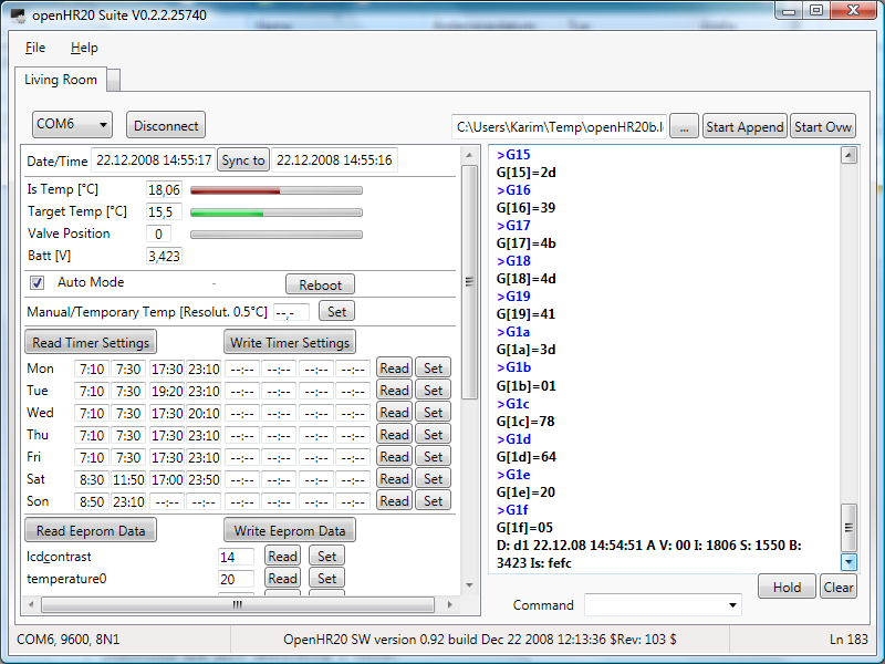
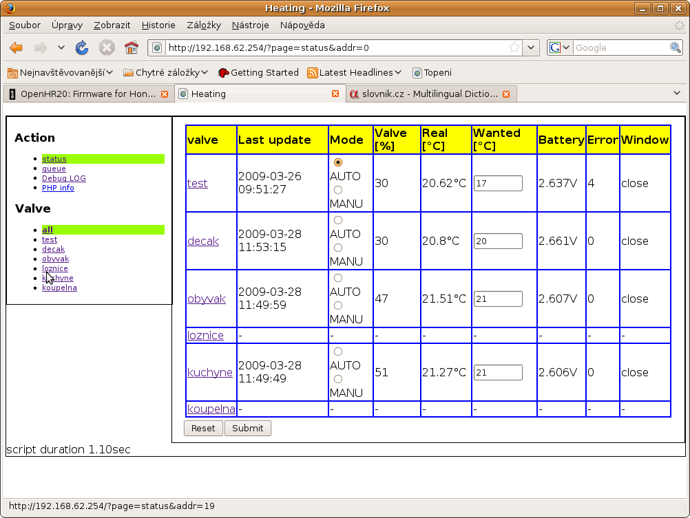

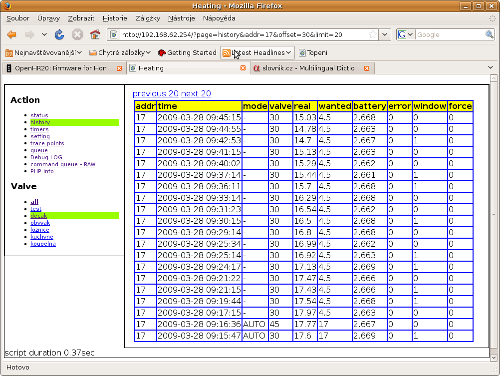
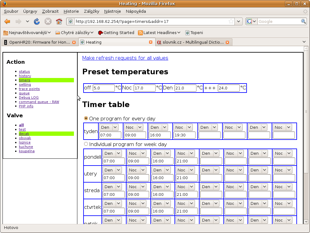

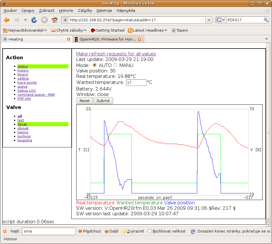
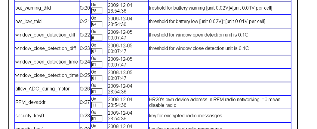
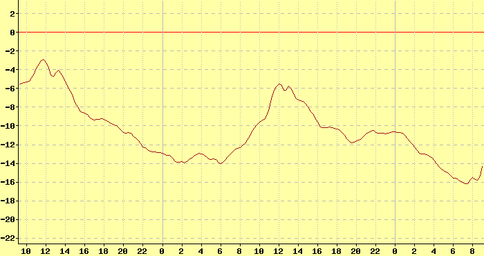
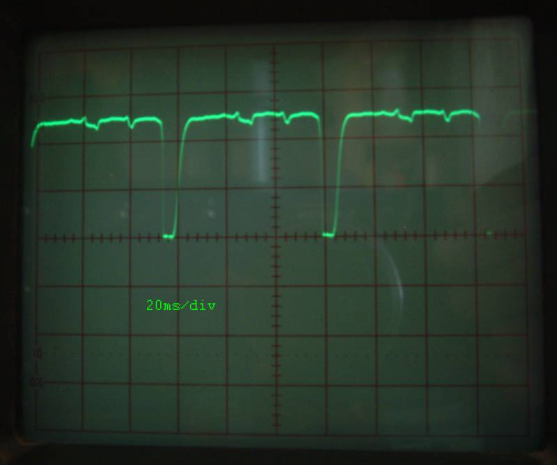

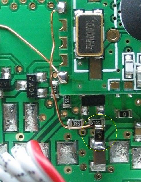


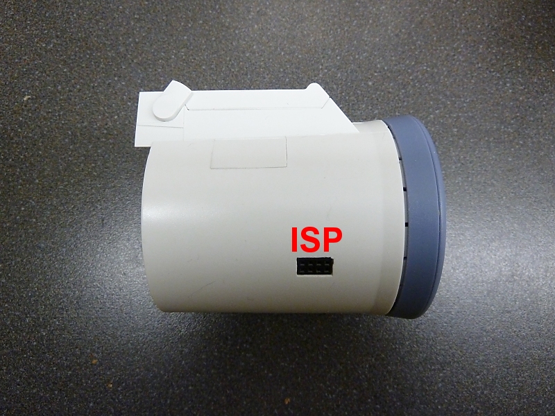
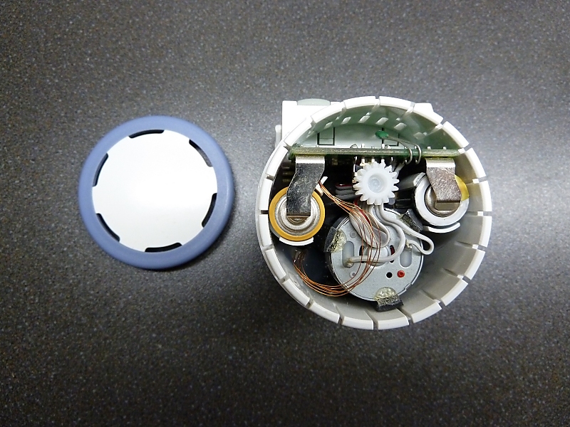


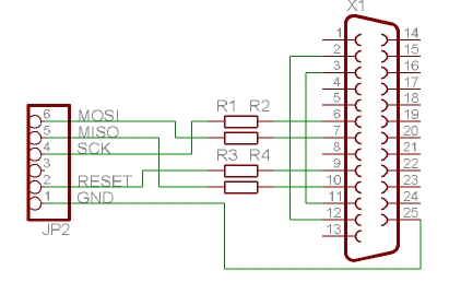

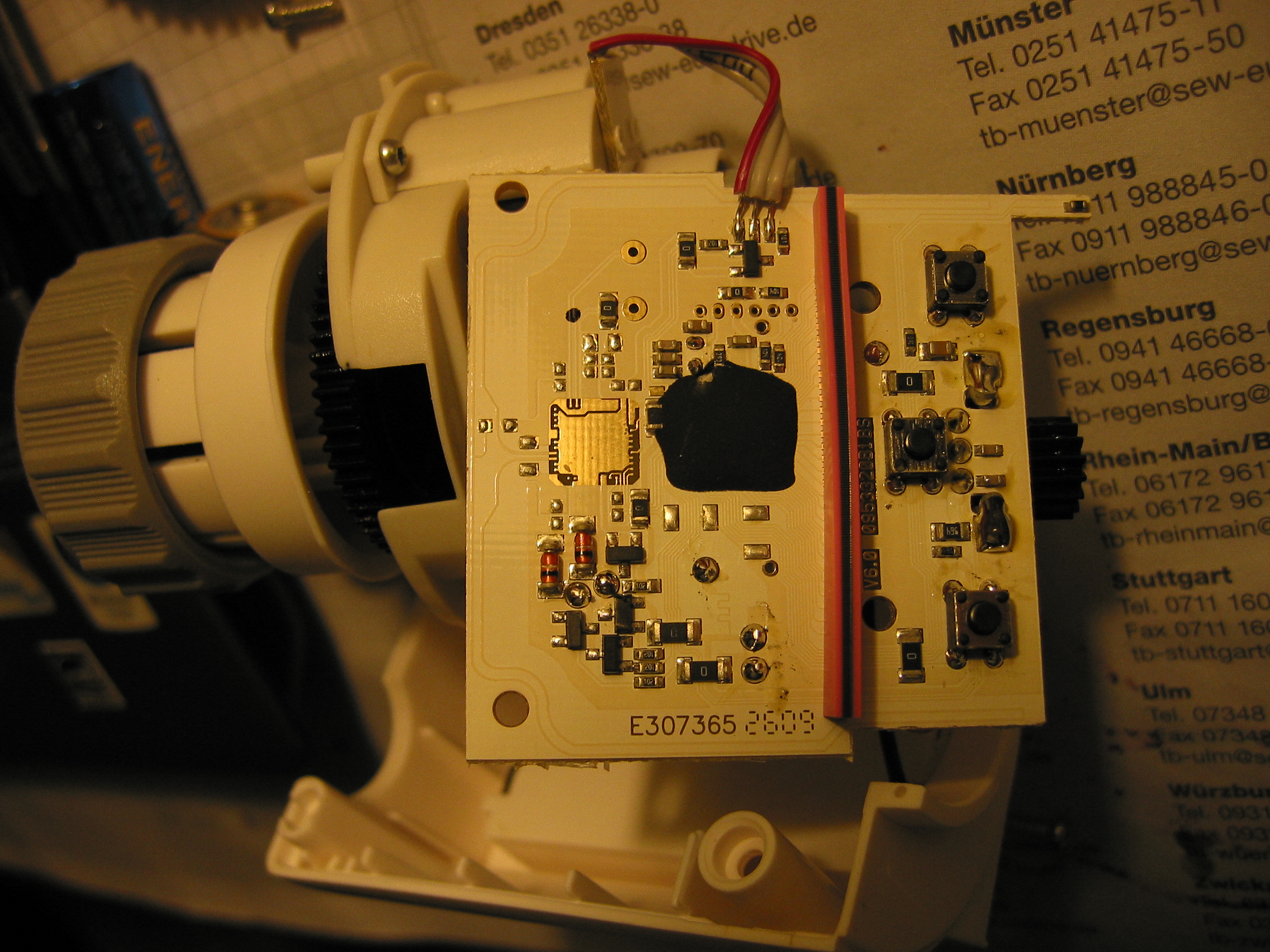


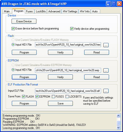
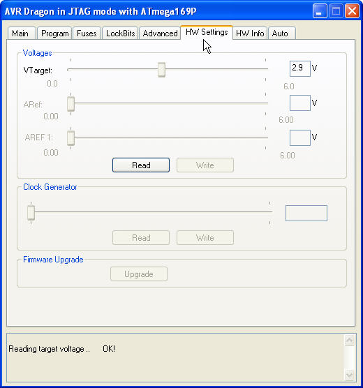
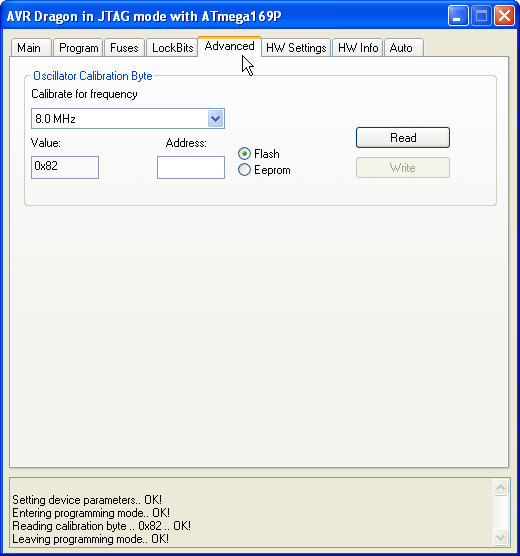
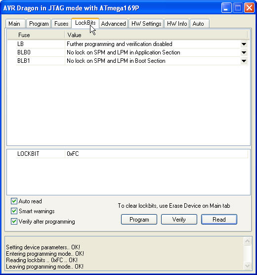
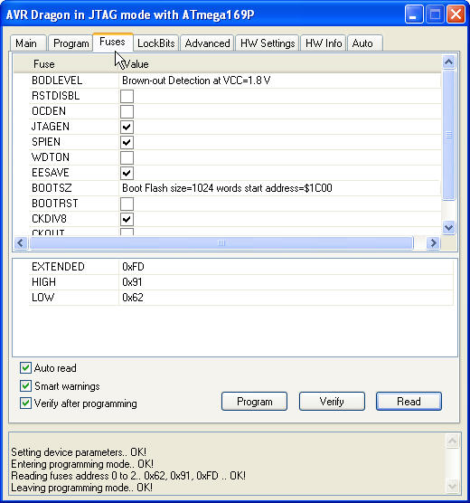
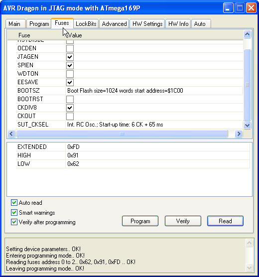


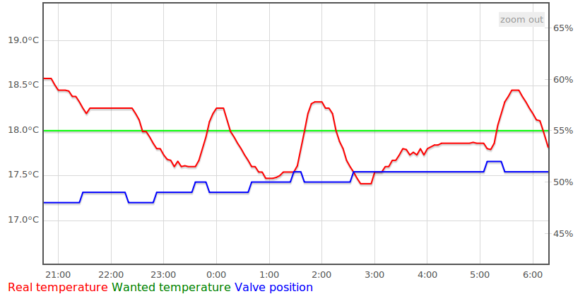

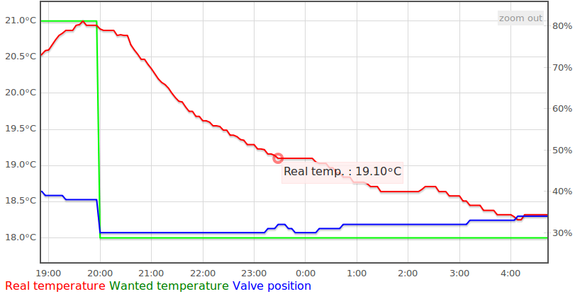

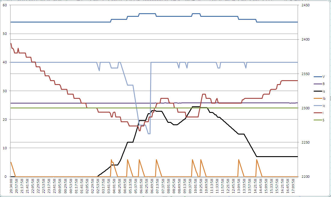
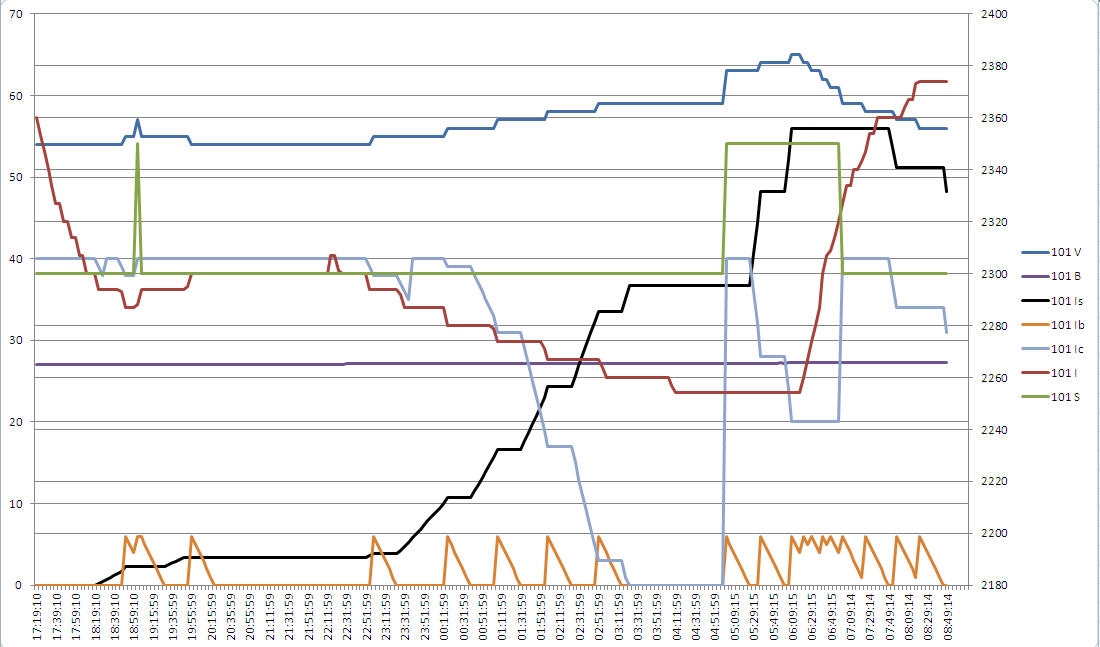
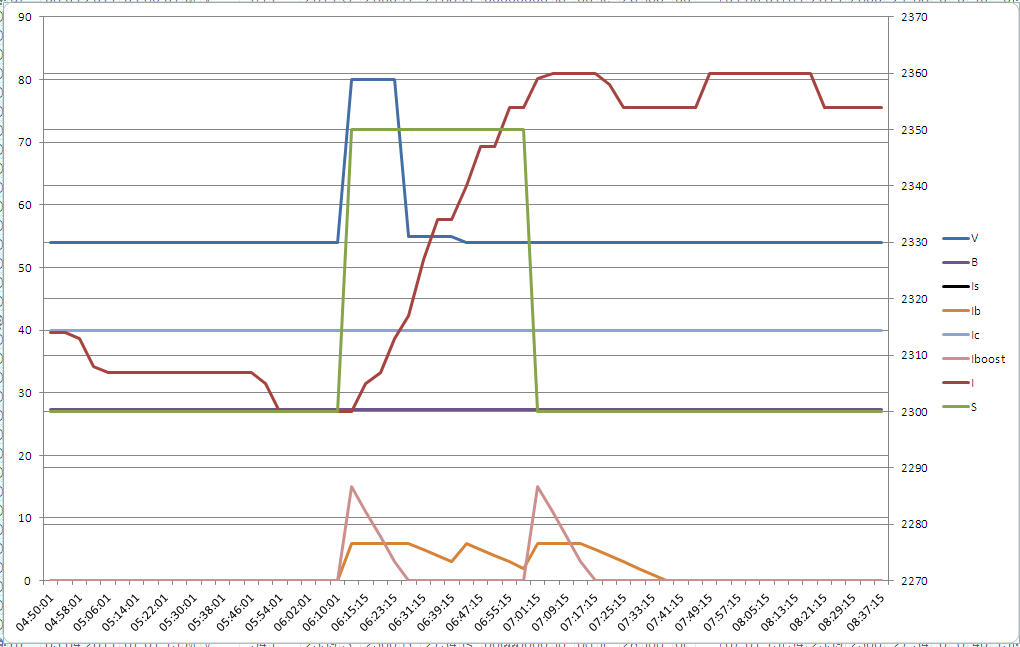

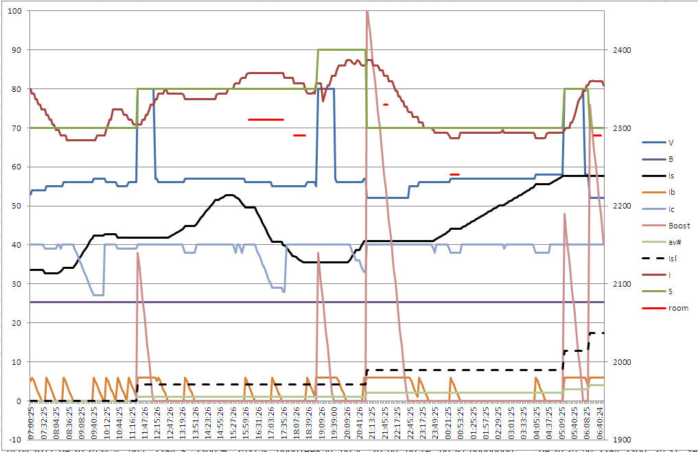

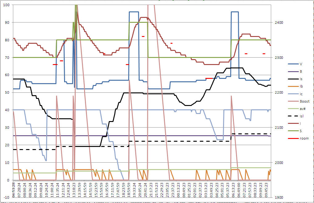

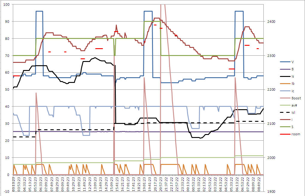

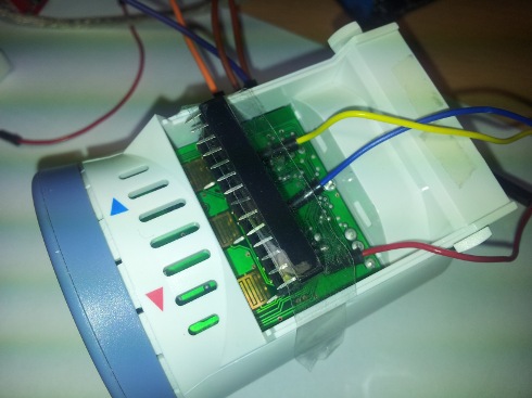


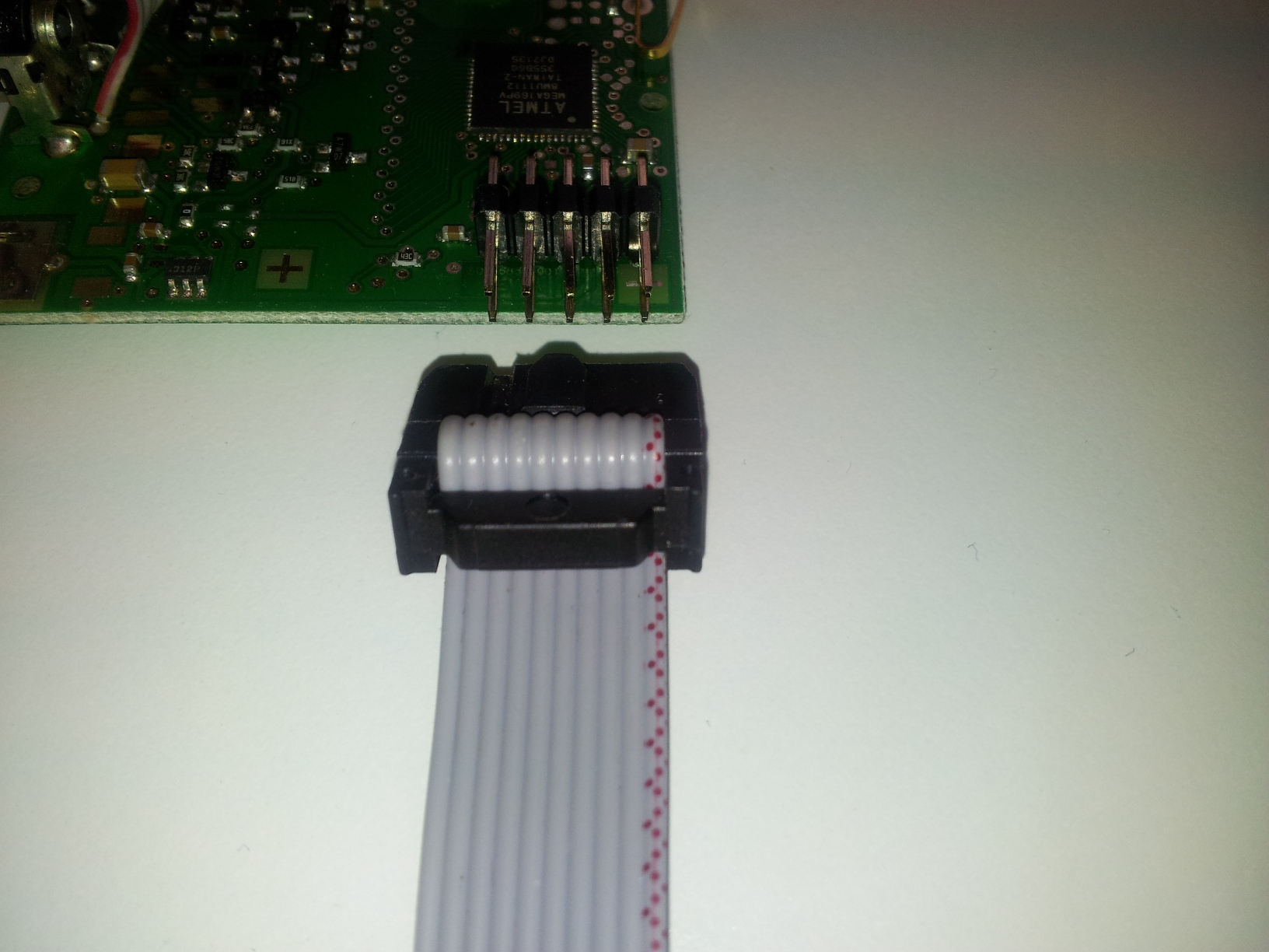
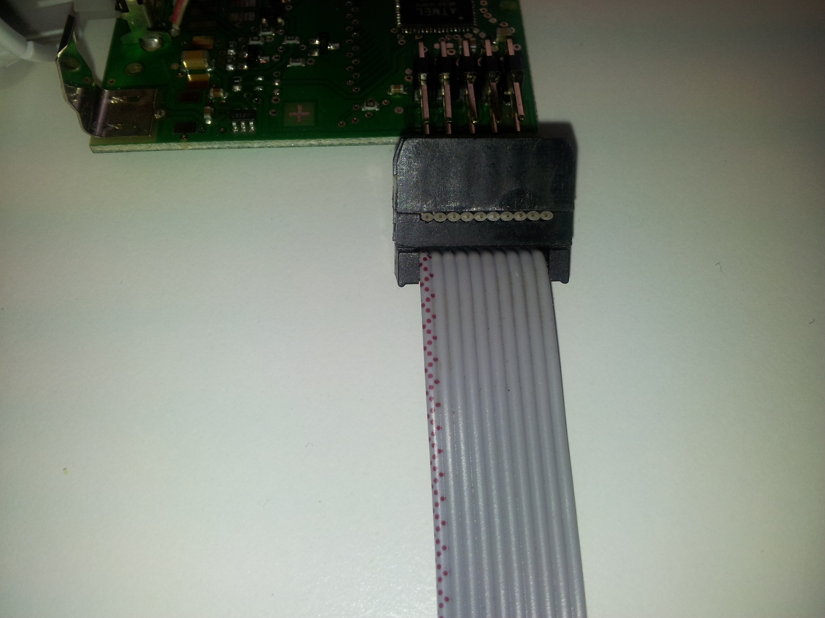


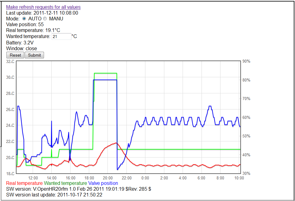
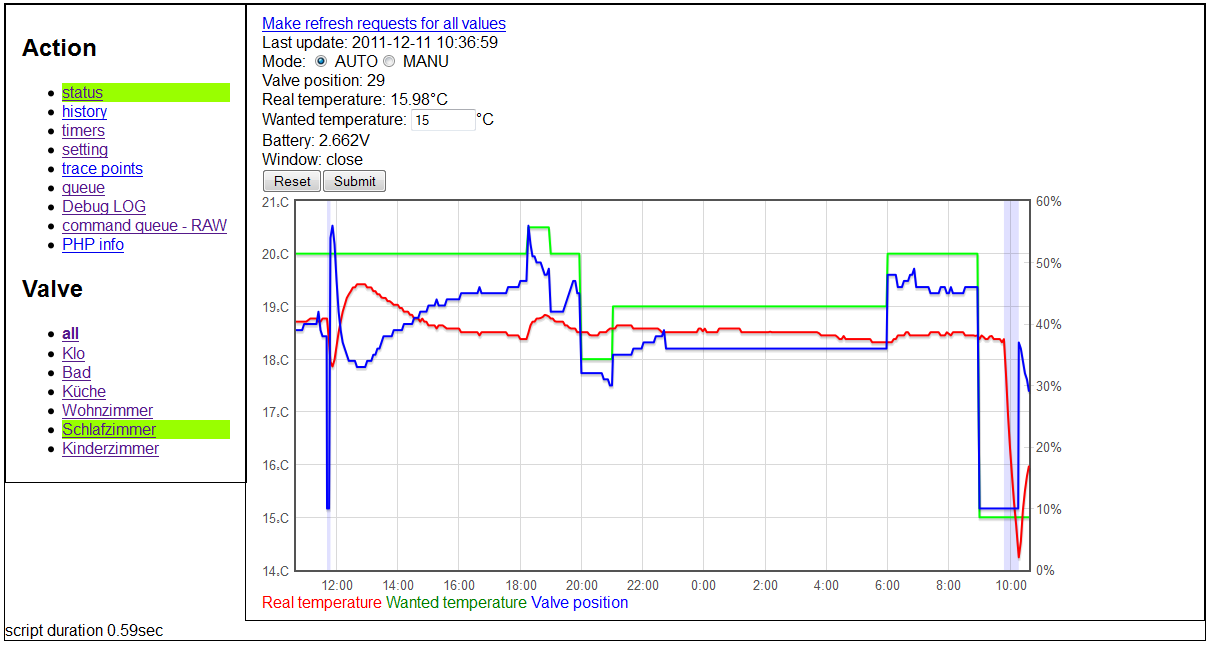
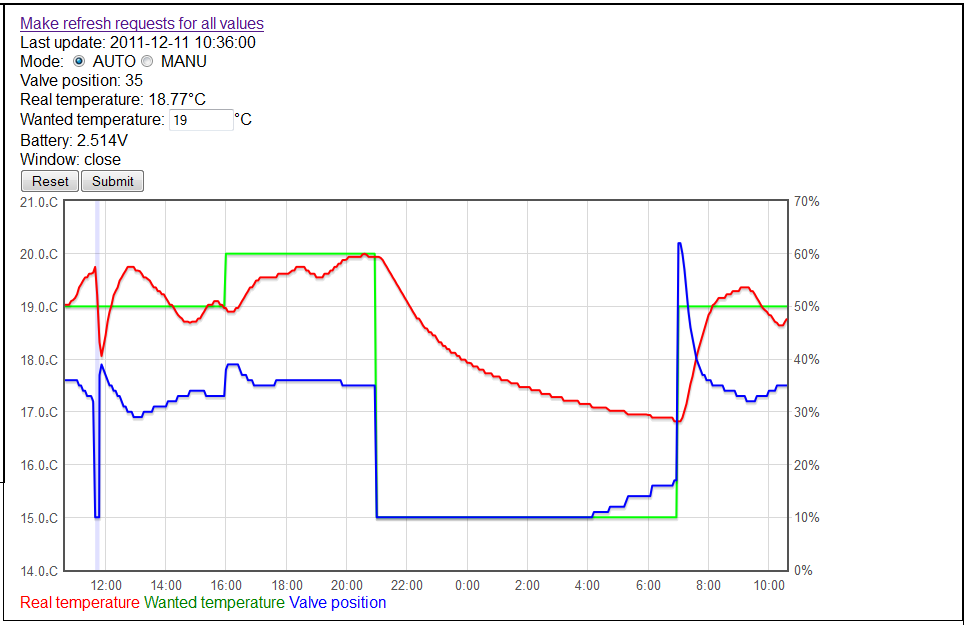

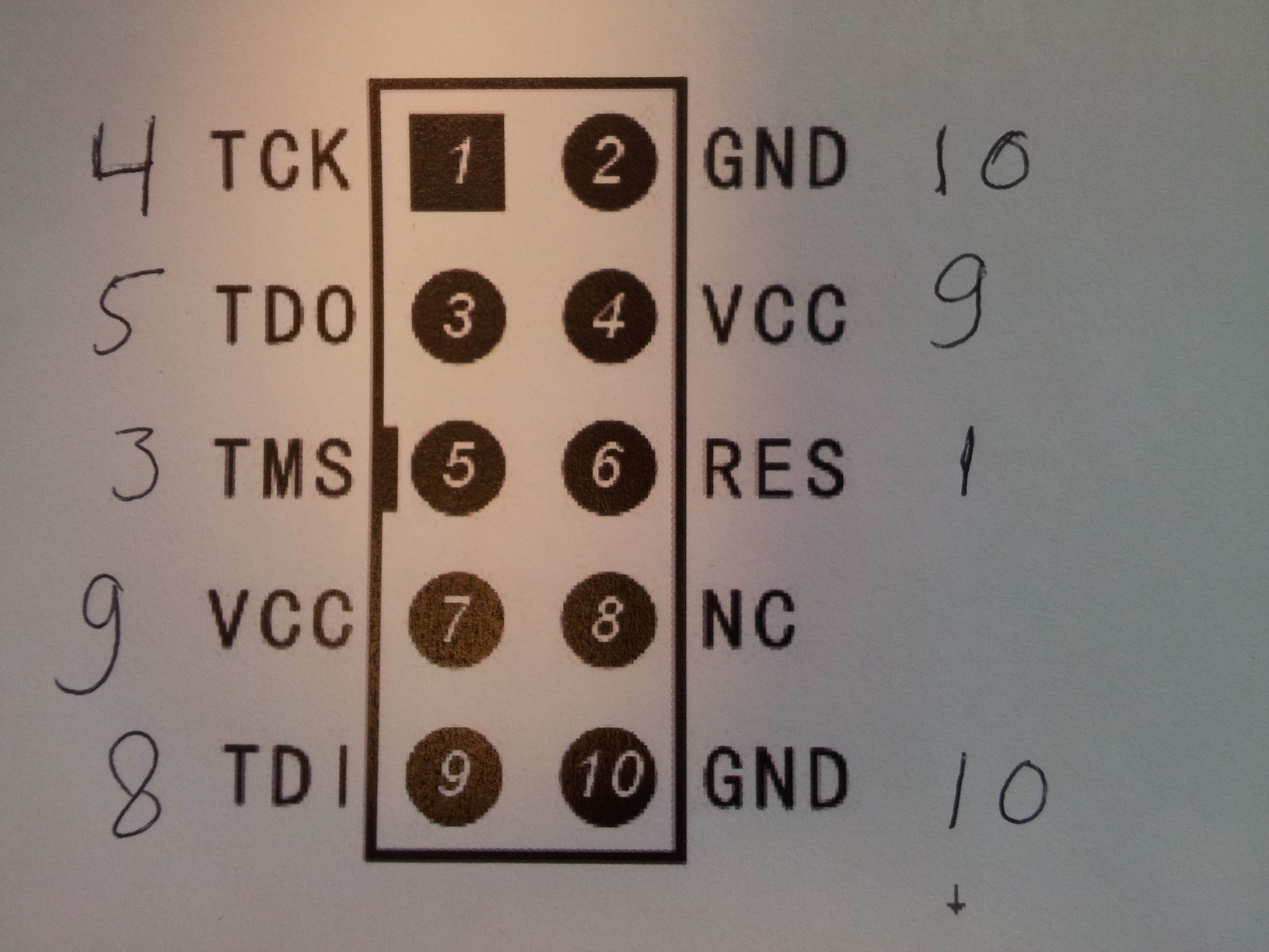

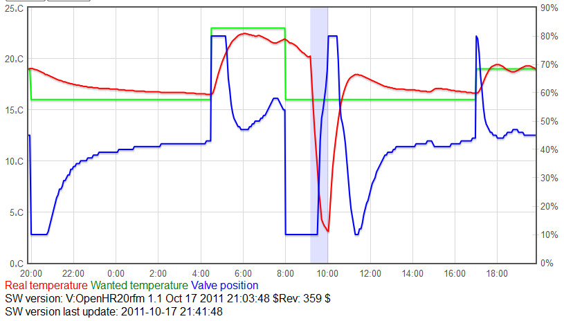

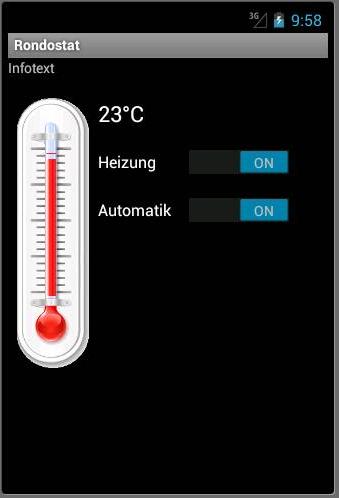


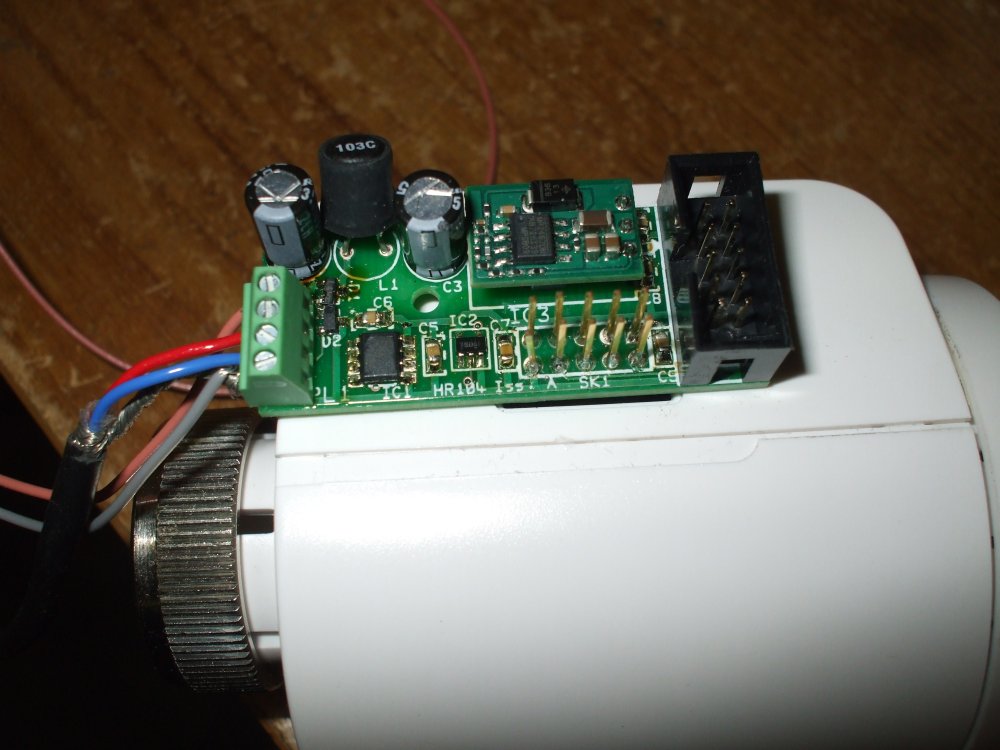


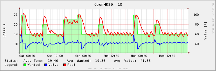


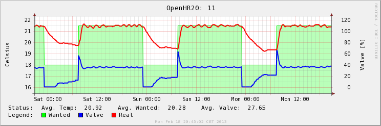
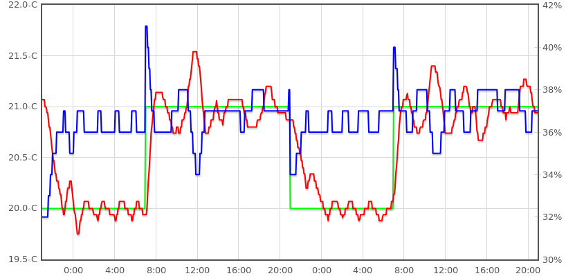


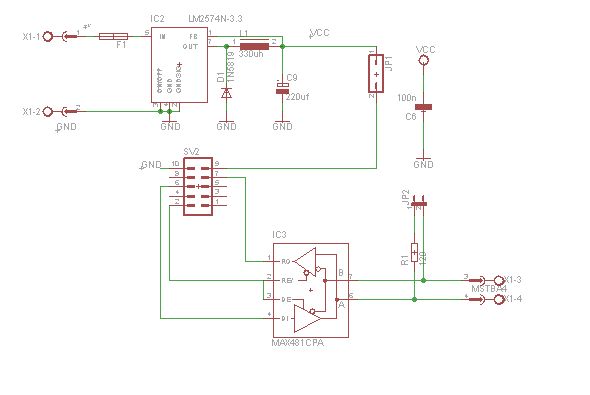

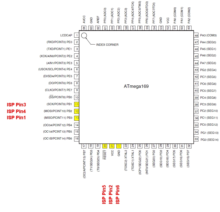

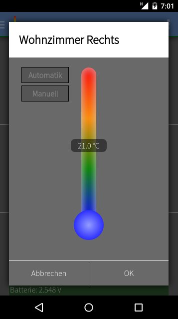
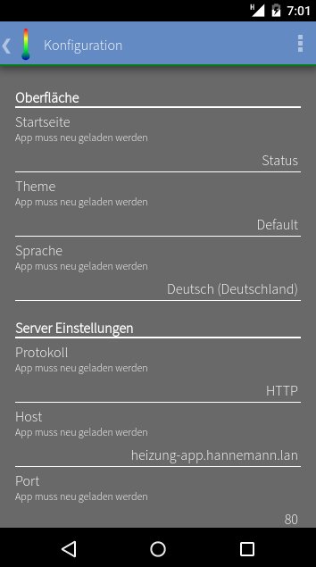