Hi all,

I'm new here and want to control my home using the HR20-style and a
simple and modified Moduline 15, to turn on and off the central heating
unit.

I've (almost) read the entire thread, but still have some questions:
1. Have anybody used the HR20-Style instead of the 'old' HR20?
2. Does anybody know if the RFM12B works and if it's the same soldering?
(http://jeelabs.com/products/rfm12b)
3. Is there some step by step manual how to do the complete
modification? It's pretty hard to find  all the steps in this thread...
If not, I will try to make one and ask for your verification.

Thanks in advance!

BTW There are a lot of posts about the master board. I use a lot of
these: http://jeelabs.com/products/jeenode (Quite cheap and easy to use)

Justin
Justin M:

add 1) It is not confirmed. But it looks like same HW as HR20.

add 2) You can use RFM12B. Compare to RFM12 you can omit pullup on the
FSK/DATA/nFFS pin. I have RFM12B also.

add 3) maybe later.

I know about http://jeelabs.com/products/jeenode It can be used as
"master" in this application. But I use my own HW because jeenode does
not support JTAG ICE to debug. Current SW is not Arduino compatible,
this mean that you will need small modification in source code (pinouts
and change mega 32 to mega328) and write it into this HW raw without
Arduino.
jbodry:

Thanks for the quick reply!

1) I will order one and try and post my findings
2) Just SW wise I suppose?
3) I will work on this and post it back


By "Current SW is not Arduino compatible" you mean the Master side?
Because I have my own protocol for wireless transfer (For any type of
device like lamps, switches, dimmers, temp sensors and so on), just have
to change the slave source...

I ordered an AVR Programmer
(http://www.ebay.nl/itm/ws/eBayISAPI.dll?ViewItem&item=170725446910&ssPageName=ADME:B:EOIBSA:NL:1123#ht_1730wt_1398),
but that doesn't work?
Justin: I use HR20 style home expert with jiris soft for about a year
now. Electronics are 100% kompatible (I did not want to write "the same"
because I never had the old hr20)
Richard G. wrote:> Justin: I use HR20 style home expert with jiris soft for about a year> now. Electronics are 100% kompatible (I did not want to write "the same"> because I never had the old hr20)
Thanks for your reply! I will also put this in the 'manual' ;-)
jdobry wrote:> For JTAG programming (HR20 connector) you need JTAG AVR tool. Cheapest> is this> http://www.ebay.com/itm/AVR-JTAG-AVR-USB-Emulator-Simulator-Wide-Operating-Voltage-Buffer-Chip-/160685211172?pt=LH_DefaultDomain_0&hash=item256995be24> But it is clone of obsolete HW. This means, that support only "old> school" AVRs. Ex: support mega169p used on HR20 but not almost same> mega329 on HR25.
I've modified a similar cheap JTAG programmer to allow it to program the
329 used by the HR25. Obviously I didn't buy a Dragon due to my
community spirit and not my cheapness. ;)
I've taken AVRminiProg and hacked it to use the serial port. The changes
are truly awful but get the job done. It allows JTAG programming the
HR25s in the same way as HR20s. The original ebay programmer I've got
had unprotected code, allowing that to be read and flashed back to
restore its former abilities. More details at
https://sites.google.com/site/slangey/misc/honeywell-hr25/jtag-usb-ice-mk1
. It may be a different one from the on Jiri posted, but likely similar
at HW layer at least.
Bruce
PS I was surprised the stick code was unprotected. I gave up trying to
disassemble and change the code for the 329... perhaps others have more
strength and/or better disassemblers.
Hi everybody,

I accidentally destroyed the temperature sensor on my HR20, can anybody
on this list help me get the data for the sensor, so I can get a
replacement?

Thanks in advance.
Hi Flemming,

there is a document about the analysis of the HR20 hardware [1] which
contains information about the AD converter input from the thermal
resistor (table 9).

The thermal resistor is in series with R3, so it should be possible to
calculate the data of the thermal resistor.


[1]
http://openhr20.svn.sourceforge.net/viewvc/openhr20/trunk/doc/Analyse%20HR20.pdf?revision=8
HI Stan,

Thanks. Based on the document I found the following:

The Analysis.pdf documents the sensor to be an NTC thermistor, and lists
a lot of measurements at various temperatures.

From this I got the following:
25 degr.C = 397 counts, probably measured with a 10 bit ADC.
Supply to AVR: 3.3V
Thus, 397 counts equals 1.279 volt.

From the schematic and tracing the images of the board, I found:
The R3 SMD Resistor is marked 43C, suggests it's 27k4, 0.5%

Calculation: (See this as a simple schematic, top to button)
3.3V
27k4 = 2.021V = 73.74uA
1.279V
NTC = NTC Nom. calculated to 17k34
0V

Closest match to the calculated NTC value seems to be Vashay/dale
01M1752SPC3 or 01C1752SPC3, both have 17k5 as nominel value.

However, both are not easily available, and costs as much as a new HR20
or HR25. :-(
Hi Stan,

Yes, almost that price (20 EUR without shipping).
But looking around I did find some cheaper alternatives, such as at
Mauser, where the price goes down to only about US$ 5 (without
shipping)... but the ETA lead time is at least 7 weeks.

I'm considering if it won't be quicker to use a more readily available
(and cheaper) NTC and simply rewrite the conversion table. Well... time
will tell...
I've been trying to solve my problem with the support people of the ebay
seller I got the programmer off (hongkong_electronics, they've all been
extremely helpful and really friendly by the way, I'd strongly recommend
them.)

There's one more question he'd like me to answer before he ships me a
new programmer, to which I don't know the answer myself: "if your target
board has set the JTAGEN fuse"

Is this something I would've needed to do myself, or would the HR20 have
come with this fuse set?

Thanks for all the help!
Ah, just to clarify, in order to make sure the problem isn't with
avrdude, I've been trying to get my programmer to work using avrstudio 4
on a windows xp virtual machine.

I know with avrdude I'm first supposed to set a fuse, but as far as I
can tell, I can't set one with avrstudio until I've actually connected
to the device first? (Which is the point where I'm getting the invalid
device id error.)

Or is there something I could do in avrstudio before trying to connect?
Does anybody has any experience using AVR Studio 5? Version 4 can't be
installed in Windows 7....

I would love to use a linux version (avr dude), but to make sure the
fuses are right, I would like to set this in Windows first. (using the
screen captures)

I found most settings in AVR Studio 5 to set the fuses and lock bits,
but not the Advanced and Board settings. Maybe these are only available
when the board is connected?

One other question:
Should the cable be connected like picture 904 or like 847?

Thanks!
Justin M.:

AVR JTAG cable can't be connected to HR20 directly. It have different
pinout, therefore you need cable with special wiring. See to my previous
posts.

About AVR Studio 5: By my mean it is worst decision from Atmel. It can't
work with JTAGICE1. It is based on MSVisualStudio = vendor lock. Atmel
buy key winavr developer to this project = factical end of winavr
project.
Justin M. wrote:> Does anybody has any experience using AVR Studio 5? Version 4 can't be> installed in Windows 7....
Hmm, I have AVR Studio 4.18 installed on Win7 32 bit, and I use an AVR
Dragon for JTAG.
Marco G. wrote:> Justin M. wrote:>> Does anybody has any experience using AVR Studio 5? Version 4 can't be>> installed in Windows 7....>> Hmm, I have AVR Studio 4.18 installed on Win7 32 bit, and I use an AVR> Dragon for JTAG.
I've got it installed also. (Win7 64 bit)
You'll have to wait for ages, but it will finish in the end...
Hi,

three days ago I flashed the last 3 HR20 with HW window detection, now
all 6 valves use a reed contact. That works great :)

But 2 valves (Kinderzimmer + Schlafzimmer) now have problems to
reach the wanted temp, see the attached pictures. Is that the same
effect Richard has seen?
Wohnzimmer for example is working, even I flashed it the same day with
same software and EEPROM.

Both failing valves have fresh batteries, and I tried to remount them
several times. To which position do I have to turn the blue part before
mounting? Near 0% or near 100%?

This is my setup:
Hi!

I have the same problem like it can be seen in "Kinderzimmer.png". So I
increased P_Factor (06) and P3_Factor (05) to both 0x50 and now I come
close to wanted temperature. But of course there is much more vent
movement and oscillating now, because a small change in temperature can
case the vent to to a change of 30%...

What about the following idea: If temperature is far away from wanted
temperatur (1 or 2 °C too high or too low) open or close valve
completely to speed up heat up or cool down.

Chris
"If temperature is far away from wanted temperatur"
It is exactly why we have "P3" regulator. In other words if we have
difference 1 degree = 100 in 0.01 units.

impact = P*100 + P3*100*100*100 = P*100 + P3*1000000

P3 impact can be stopped by valve limitation very easily.
Just a short update.

I got the HR20 flashed. My problem was that the power supplied by the
HR20's batteries was insufficient for the programmer. After hooking up
the V+ of the programmer to an external lab power supply, all started
working fine.

It still complains about the OCDEN fuse, and the verification still
fails, but the HR20 is now running OpenHR20, so all is fine as far as
I'm concerned :)

Thanks for all the help!
Jiri Dobry wrote:> "If temperature is far away from wanted temperatur"> It is exactly why we have "P3" regulator. In other words if we have> difference 1 degree = 100 in 0.01 units.>> impact = P*100 + P3*100*100*100 = P*100 + P3*1000000>> P3 impact can be stopped by valve limitation very easily.
Sorry still do not catch it - If I want to increase p part, In which
situation should I use p or p3
hi at all,

i'm developing my own firmware for the HR20 and i have some questions
about to save power.

my HR20 is currently running in POWERSAVE mode and it needs 330uA
current. In POWERDOWN mode it will need 110uA but with LCD not working,
it will work in POWERSAVE mode.

in which mode are you running the HR20? and do you have some ideas for
me for to save more power?

thank you very much

Jan
Problem on power save / power down modes on HR20 is internal pull-ups.
For encoder. It have 2 lines, and only one have external big pull-up.
This line can be used as interrupt source. Second need pullup in MCU.
But in must be enabled only during read. Otherwise depending to encoder
position this pull-up it can have more current that complete MCU.
For sleep modes in source you can see to
http://openhr20.svn.sourceforge.net/viewvc/openhr20/rfmsrc/OpenHR20/main.c?revision=359&view=markup
lines 136-145

It yse both modes idle/sleep dependig to situation. Sleep is prefferred,
but for serial communication, high precision timer or AD conversion I
need clock = Idle mode.

PS: why you will write complete new code? Current code is under GPL =
you can use it and add what you need.
but with idle or sleep, the lcd dosn't work, damn.
but thank you for the tip to disable the pullups, and i made every
unused input to an output, now i have a consumption of 283uA.

did you have measured yours HR20 current consumption?
and how do you initialize the lcd controller, like in the analysis of
the HR20 document?

what interrupt do you use, to wake up the mega169. timer2?


PS: i write my own fw, because i have an existing system here in my
house that consists of temp.sensors and an main-heater-ecu, which are
using the rfm12 to communicate, and now i want to integrate the HR20
into this system.
I have 30-40uA with LCD.
For wakeup I use T2 owerflow, T2 compare (for timers), pinchange from
encoder and pinchange from buttons.

PS: You can use this code and rewrite only communication protocol. This
project use rfm12b also.
but the problem is, i programm in bascom and i have no knowledge in
programming in C.

and i've tested all powermodes, my min. consumption is 280uA. i use the
timer2 overflow too for waking up the processor. but in powerdown mode,
the timer is disabled, and for that, the processor didn't wake up from
sleepmode.

you have 30...40uA in powersave/idle mode???

Jan
good morning jdobry,

i have tested some different lcd-init.parameters, and i can decrease the
consumption to 217uA, but it's still too much.

please, can you tell me which hardwaremodules you switch off? especialy
the 3
V3-Pin (pine.6 from mega169). when i set this to logiclevel 0, the
current is more than 18mA, only when i set it to logiclevel 1, there is
minimum current.

i think, that the hardware arround the atmega causes the current
problem. i have an other board, with attiny84 und rfm12, and this board
current consumption is 5,6uA in sleep.

thank you,

Jan
And i observed, that the new version of the hr20 (2.04) uses much less
current than the older version. the same software runs on the new one
with 15,6uA (instead the old one with 36uA)

Jan
Hello,

@Marco G. (stan)
You posted on 2011-12-11 10:56 a part of a definition file.
There is an #define MENUES_AUTOBROWSE 1 which I could not not find
anywhere. Is this your own extension ? Does it automatically scanning
the menue ? If it is so , would you like to publish your changes ?

Ronny
Hi Ronny,

yes it is my own extension, and yes, I wanted to browse through the
temperatures and valve position automatically.
But no, it does not work :(

This is what I changed in menu.c, maybe you can check and correct it:
hi,

This is a good project :)

I have a question : In the original firmware, it is possible to disable
frost protection when the HR-20 is in OFF mode ?


thanks !
I know this is not really the correct place to post this, but I have
some information about the original software on the HR20

I have just got one of these unit, and found that it wont display the
room temperature, just the set temp...

After browsing the net, I found the German instructions for the HR25

There seems to be a programming mode for some settings...

This is for the original software, and I don't know the version.

If you hold down the Prog Button for over 20 seconds
(Upto 3 seconds gets you into setting the programs times)
(Over 3 and less than 20 gives you the option to change the date...)

After 20 seconds it shows
01:00 with the 00 flashing
turning the knob lets you change it from 00 to 99

when you press Prog again it shows 02:00, then 03:00 then goes back to
the normal display

A guess on the options are as follows

01 - enable / disable summertime (This is a guess)
02 - 00 = Normal, 01 = Valve position ?, 02 = Show room temp...
03 - Open Window detect options ?

All are normal set to 00

I have changed parameter 02 to Value 02 so it shows room temerature...

Have Fun...

    Regards Wonko The Sane...
Wonko The Sane : Thanks for your answer.

Sorry if I haven't post in good section, but I'm french and don't speak
german... The other sections are german spoken.

I will try to get a french or english version of the HR-25 instruction.

But, I'm interresting by the open firmware if I can't set the HR-20 to
work as I want...

A+
just a info:

it seems that the master communication doesn't work in rev 364. i'm
using a uart/usb converter (from elv based on CP2102) on rx/tx and my
master board did not answer anything. with rev 362 (or version 1.0/rev.
285) i have no problems.  rev 363 generates a compiling error when using
'make all' on my system.

maybe the changes for the hr25 in common/rs232_485_hw.c are the reason.
but it's to complex for me to understood or fix it.

hope that help.

thanks for this project!
Hello again,

i've found a little error in com.c. The command (UART and RFM) for
set/change the Mode compares the parameter with 1. That's a problem,
because so it support only set/reset and not the other options like
CTL_CHANGE_MODE or CTL_CLOSE_WINDOW_FORCE witch CTL_change_mode()
supports.


Here ist the Diff: The full file is attached.
1
--- .../com.c-revBASE.svn002.tmp.c Mo 21. Mrz 22:58:53 2011
2
+++ .../rfmsrc/OpenHR20/com.c So 12. Feb 16:21:13 2012
3
@@ -505,7 +505,7 @@
4
break;
5
case 'M':
6
if (COM_hex_parse(1*2)!='\0') { break; }
7
- CTL_change_mode(com_hex[0]==1);
8
+ CTL_change_mode(com_hex[0]);
9
COM_print_debug(1);
10
break;
11
case 'A':
12
@@ -607,7 +607,7 @@
13
}
14
break;
15
case 'M':
16
- CTL_change_mode(rfm_framebuf[pos++]==1);
17
+ CTL_change_mode(rfm_framebuf[pos++]);
18
COM_print_debug(2);
19
break;
20
case 'A':
I've also implement a little feature inspired by ELVs FHT80b:
Rolling throu the timers temperatures (night, day, comfort) with the
C-Key.
The info-display-function is now available via the Prog-Key.

Here's the diff. The full file (Menu.c) is attached.
1
--- .../menu.-revBASE.svn002.tmp.c Mo 21. Mrz 16:18:05 2011
2
+++ .../rfmsrc/OpenHR20/menu.c So 12. Feb 15:24:32 2012
3
@@ -243,6 +243,18 @@
4
case menu_home5: // alternate version, battery
5
#endif
6
if ( kb_events & KB_EVENT_C ) {
7
+#if MENU_ENABLE_TEMP_CHANGE_WITH_C
8
+ if( CTL_temp_wanted == temperature_table[3] ) // super-comfort > night
Hello again ;-)
i've extend the master to read temps from ds18[x]20/22 sensors from
1-wire.
It's based on this great work by Martin Thomas:
http://gandalf.arubi.uni-kl.de/avr_projects/tempsensor/
I've added some files to the master source (in a seperate directory
'ds18x20') and extend the com.c file to include the files and added a
new Command 'X'. It's a little bit dirty, but i want to make as few
changes as possible to the existing code.
To connect the sensors i use the free PA0-Pin on the ATmega32. The
library supports DS18S20/DS1820, DS18B20 and DS1822 with parasite or
externally power supply.
There is a new command in the master-protocoll 'Xhh' where xx stands for
the Sensor ID as hex.
To init the sensors and get a list of all available type 'X00'. The
master will answer 'X00' if there is no sensor found, 'Xff' is something
goes wrong or Xhh for each sensor that was found. After Xhh you can see
Name/Type, Power and ID of the sensor.
To retrieve a temp, type Xhh where hh stands for one of the founded
sensors. The Answer is 'Xhh T:+nnnn'. The temp-format is like the
typical master/OpenHR20 format: temp * 100.
Exsample:
> X00
< X01 N:DS18S20/DS1820 P:Externally I:1051d3250208003a
> X01
< X01 T:+2120
That's all. The added zip file contains all new files and the changed
com.c.
HTH
Basti
Hello again,

in rfmsrc/master/com.c at line 450-460 is a case statement for command
'L' (KeyLock) missing. It should be near the statements for M, A, T, G
or R where len is set to 1.

Without this, the L-Command doesn't work via RFM.

BTW: V has also no case-statement. But this is not a problem because
len=0 is default. But than the case-statement for D is unnecessary...

HTH
Basti

PS: there is still someone who works on this project? or at least it
used?
Basti wrote:> PS: there is still someone who works on this project? or at least it> used?
I am using it on 6 HR20, 5 of them with HW window detection (magnet
contact at the window). Master HW is attached to a FritzBox 7270v3 and
running fine, since AVM has updated the USB stack in FritzBox firmware
05.xx.
Btw, I found out that even if the HW window detection says that the
window is open, the heating starts again after about 30-60 minutes. Is
that timeout intended?
Hi I am still using this code on 5 valves + master. And I have many
plans to improve it. But now I am overloaded with other high priority
tasks.

@Basti: Your patch looks ok. If you witch to have write access to code,
send me email with your sourceforge account name. ("M" command has idea
to support only on/offf, but now is not reason to limit it)
sure I do use 4 HR20 with R364 and having some trouble with make/compile
of R364 ... see some posts above. I wrote theese extensions:
TEMP_COMPENSATE_OPTION BLOCK_INTEGRATOR_AFTER_VALVE_CHANGE
BOOST_CONTROLER_AFTER_CHANGE
Usally I have those Options set:
HW_WINDOW_DETECTION=-DHW_WINDOW_DETECTION=0
RFM=-DRFM=0
NO_AUTORETURN_FROM_ALT_MENUES=-DNO_AUTORETURN_FROM_ALT_MENUES=1
TEMP_COMPENSATE_OPTION=-DTEMP_COMPENSATE_OPTION=1
BLOCK_INTEGRATOR_AFTER_VALVE_CHANGE=-DBLOCK_INTEGRATOR_AFTER_VALVE_CHANG
E=1
BOOST_CONTROLER_AFTER_CHANGE=-DBOOST_CONTROLER_AFTER_CHANGE=1

If I run MakeAll without any of theese Options mentioned above (e.g.
with R364 makefile) this happens:
(.vectors+0x38): relocation truncated to fit: R_AVR_13_PCREL against
15
symbol `__vector_14' defined in .text section in obj/rs232_485_hw.o
16
make: *** [hr20.elf] Error 1
17
Build failed with 1 errors and 0 warnings...
But as I said, when I use the old rs232 routines (from common)
everything compiles fine.

It may also be a linker/compiler prob. Because if I set controller.c
line 185 as a coment:
//                      CTL_temp_wanted_last=temp;
everything works fine too ...
Hello,

nice to read that some are still active.

@jdobry:

If you want, i would like to patch some of the things i've found. And if
it's ok for you, i will add the new features i've created with #defines
to enable/disable them. The change of the C-Key i would disable per
default while the new X-Command for external Temp-Sensors for the Master
i would enable per default because it changes nothing if you don't use
it.

i'm currently working on a HR20-Server running on Windows developed with
C# in .NET (so it's maybe possible to run it under Linux with Mono). The
Server communicates with the master and has a built-in http-server for
some web-pages to control, analyse (already working) and configure
(todo) the HR20s.

I plan to share it and it would be great, if there was some space
(around 400-500 kb) for this under the rfmsrc- or Tools-Directory.

@Richard / @All:

I'm unable to compile Rev. 363. and with Rev. 364 the master don't work.
I've spend a little time, but what i've checked was very strange.

Rev. 363 give some compiler errors on places, where nothing in Rev. 364
was changed. But Rev. 364 compiles without errors.

Maybe diffrent gcc- or avr-lib-versions are the problem. Maybe the
changed make-files.

If i find some kind of motivation, i will analyse this... currently i'm
happy with Rev. 362.

greetings
Basti
Problem on compilation can be caused by jump/call instructions size. See
to makefile, it is optimized to prefer short versions to fit it into
small flash. I have not problem with compilation, I am not abble repeat
this on avr-gcc/linux

@Basti: why .NET? In relity you need 24hours switched on computer.
Teoreticaly it can be virtual computer on cloud.
PS: I kick off MS from my house and I am happy. And mono have usualy
problem with some .NET features.
@jdobry:
I love .NET. That's the reason. And there is already a 24h running
win-pc here for TV-Recording and other server function like E-Mail, svn,
etc.

I've just read that Mono doesn't support the EnityFramework i've uses to
access a SQLite-Database via Linq. Curious, that Mono supports Linq to
MS-SQL-Server but not via the DB-independet EnityFramework. I should
seperate the DB-Access in a Backend-Class and create a variant with easy
sql-text-statements.

As far as i see, there are no other features i've uses, that mono
doesn't support.

If there is interest, i try to keep the server mono compatible.
If you have problem with compilation 364 on winavr 20100110 please move
rs232_485_hw.c to second source group. Problem is caused by size
optimalization and winavr. In Makefile, please make change like this:
Marco G. wrote:> Btw, I found out that even if the HW window detection says that the> window is open, the heating starts again after about 30-60 minutes. Is> that timeout intended?
That's the screenshot.
I'm using it too, on 7 rondostates. However, I do not use the master
board because I have my own control connected to the rondostats (rs232).
I take wantet and real temperature and vent position to control central
heating temperature.
@Jiri:
Good point, I didn't see that.
But the frost protection exits the window open mode, and even if the
window is still open, the heating tries to reach the wanted temperature
and wastes the energy.

If the temperature here drops again (at the moment it's +5°C), I will
try to add a timeout (30 minutes?) for the  window open mode, until
that timeout the frost protection is disabled.
Hello,

I use this project too . In my configuration there are 3 HR20 and the
Master based on the PCB from Marco (stan) . I have added an Humidity
Sensor and a barometric pressure sensor to my master.
I have played a littlebit whit the onewire extensions and i think it is
a good idea. But it is not the the right place in the communication
routine because the conversion take a really long time(max 750ms). And
this will break the timing for the communication whit the HR20 from time
to time and this will lead to an higher current consumption because they
must retransmit the corrupted message. A better approach is to use an
own thread in the scheduler and a interrupt driven communication with
the onewire devices. The communication part should only en-queue the
order. Maybe it is not necessary to use an interrupt driven
communication.But at the conversion it should not block the execution.

greetings,

Ronny
@Ronny:

i full agree with you.

But i implement it this way because of 3 reasons:
- I want to make as few changes as possible (for example: i've embed the
lib-files via #include to aviod changing the makefile). It's also easy
to put the full extension in #defines.
- The 'right' way is much more work. I use the DS18x20 Lib as a
black-box and don't understood what's going on behind.
- In practice it works for me :-)

My Server query the sensor after the N1? request. And the query rotates
between the max. 5 sensors so i've got a value every 5 minutes. That's
give good results in combination with the HR20-Status (every 4 minutes i
think).

ASAIK N1? is send on second 29 and the next possible device-query is on
second 30. So after N1? there should be one second without anything to
do for the master.

Greetings
Basti
Hi,

Has anybody used a RS485 network with the openhr20 firmware ? I have
cat5 at every radiator valve so would prefer to use cables rather than
RF modules.

Thanks,

Micah.
@basti/jiri: Who is going to make revision 365 ?

I would like to send my changes regarding the options (written by me)
and controller.c
TEMP_COMPENSATE_OPTION
BLOCK_INTEGRATOR_AFTER_VALVE_CHANGE
BOOST_CONTROLER_AFTER_CHANGE
> @basti/jiri: Who is going to make revision 365 ?

i'm not sure what you mean. i've just submit 2 small fixes (revision
365) and not planning any more changes. And Revision 366 (a makefile-fix
by dobryj) is also already exist.
BTW: I jus tried 366 - moving the rs232 routines fixed my building issue
;-)

@basti: Maybe I did not communicate very well ...
I have improoved the code from the options mentioned above and need
somebody to check them into SVN ... pls send me your mailadr via PN ...
@Richard:
Sorry, no. Please ask the admins of this project
(http://sourceforge.net/projects/openhr20/). Or maybe just post your
code here, like i do with my extensions.
Hi,

is there any recent status roundup on the project?
I am interested, but currently not willing to read through this huge
thread. Also,
http://www.mikrocontroller.net/articles/Heizungssteuerung_mit_Honeywell_HR20
seems a bit outdated, isn't it?

Of course, I am especially curious about features the firmware offers
right now.
What are the best/cheapest options for wireless interfaces? RFM12? What
do i need for a wireless master board?

It would be great, if someone provides a current kickstart into the
topics.

Thanks,
Philipp
I've got a master up and running on both a mega16/32 10MHz (random ebay)
and a Nanode RFX/Wi-Node 16MHz (www.nanode.biz). Both use the RFM12B,
but I can't get it to run at 19200 baud reliably, even side by side. It
only seems to work properly at 9600 baud. Has anyone else experienced
this, i.e. is this a known difference with the RFM12B?
Hi,

I'm new to the Rondostat HR 20 and I just took my first one apart today.
The chip is the ATMEL MEGA 169PV. I hope this isn't off topic.
My question is this: When the timer calls for the Rondostat to be turned
ON, which pin on the ATMEL goes high? My idea is to disconnect this pin
and supply externally my own timer voltage so I can turn the Rondostat
on independently of the Rondostat timer. Is this feasible and if so do I
tie the pin high or low with a resistor or just leave it floating?

Thank you in advance if you can help.

Regards

Dermot
I've just got hold of the schematic and can now see that it appears that
pins 18 and 19 control the motor through a H bridge. The output from the
timer is internal and I won't be able to isolate it.

Just one final question: Does anybody know what type of
Reflexlichtschranke (Optical transistor switch?)is used?

Regards

Dermot
Hello Dermont,

Like Marco say there is no need to control the Valve directly. The HR20
is more than a stupid Valve. It is a PID-controller. If you really need
only a dumb Valve , there are so cheaper device on the Market. A better
approach will be to control the device via a pin on the side programming
connector. This will need a little bit work on the firmware but much
lesser than your approach required.

Maybe some of this valve are an solution for you :
http://www.merten.de/download/DL_doku/639124_Stellantrieb_24_V_D.pdf

Ronny
Thanks for the comments Marco and Ronny.

I appreciate what you say about adapting the firmware but I'm afraid the
learning curve for me would be far too steep. I have no background in
electronics or programming. I have a little experience with PICAXE
projects and PIC Basic.

I looked at the simple valves but they are all mains AC operated and
much more expensive than the Rondostat, which I like because of the 3V
battery supply.

What I intend to do is to disable the Amtel chip by cutting the
connection to pin 21 and just use the H bridge, to actuate the motor,
and the opto reflector (IC2)on the PCB and connect them externally to a
PICAXE chip.

Do either of you know why IC2 is connected to 3 pins on the Atmel chip
and what are the resistors R12, R13 and R14 for? I would have thought
that just one output from IC2 was necessary to connect to an ADC pin. I
don't know exactly what the spec of IC2 is, does anybody know what it
is? My understanding of these opto reflectors is that when they are
positioned near a black surface they output say 3v and when positioned
near a reflective surface they output a much lesser voltage (or is it
the other way around?). All you have to do then is feed this output to
the ADC of a suitable PIC and you can control how your motor stops and
starts.

Once I have that accomplished I will attach an electronic timer, taken
from an electric socket timer, to my PICAXE and I will then be able to
control the Rondostat as precisely as I want.

Thanks again for you comments.

Regards

Dermot
Hello Dermont,

Maybe another aproach for you is to use the serial Interface of the
HR20. You can use your PICACE to send commands to the valve. For example
you can use it to set manualy at high or a low temperatur so the valve
will open and close.
But you should beware of problems with the powerconsumption. Bad
Software will leak many energy and your batterys are realy fast empty.
Designing software which realy saves energy is not a simple thing.

Regards,

Ronny
hi,

i successfully flashed a hr-20 with the software from the svn.

now i connected my pc through serial port, using hterm.
if i put in the batteries i only see rubish.

i tried to send commands like ?BATT and CR, but no response.


my serial port is a usb cable, i have lowered tx voltage through two
resistors. rx is directly connected.

9600baud, 1 stop bit, no parity.

any hints? thx!
Hello,

what kind of data did you see. I am not sure, but i think the protocol
has changed to an other version since a while.
Which version did you compile (from rfmsource path)? The only occurrence
of such am command i found is in a really old version in
openhr20/branches/before_refactoring_1/source/ .

Maybe you see some data like this in the API-spec from the HR20 article
on mikrocontroller.net (
http://www.mikrocontroller.net/articles/Heizungssteuerung_mit_Honeywell_HR20)

Regards

Ronny
i did the svn checkout. but i didn´t use the rfm source.
i receive some data after inserting the batteries, i can post the data
in the evening.

i also tried some commands from the article ...
so, i flashed the .elf from the original folder.

now after inserting the batteries there is a bunch of bytes received

170 177 125 053 035 111 091 155 159 191 115 053 059 191 155 159 157 157
191 159 157 139 153 143 139 .....

display shows version 1.0 (last time it said 0.99)

any hints? baudrate 9600 stop1 no parity

is the voltage level to low for the rx?
I'm using the frontend/tools/*.php. On upgrading to ubuntu 12.04, the
trick of using sqlite.so from an older ubuntu version stopped working.
To use php5-sqlite, I've changed:

sed -i -e 's/fetch/fetchArray/g' *.php
sed -i -e 's/SQLiteDatabase/SQLite3/g' *.php

I converted over my old db with (and renamed etc.):
sqlite db.sqlite .dump | sqlite3 db.3.sqlite

It seems to work again. :)

Also, not that it makes much odds, I've also done this to daemon.php -
hopefully this is correct?
       fwrite($fp,$date); fwrite($fp,$time);  // was other way around
i use a 5V serial port but i transformed the tx with two resistors. the
rx is not amplified which is usually not a problem.

i receive data after switch on and after a minute or so, but it doesn´t
send any replies if i send commands.

i´m still not sure which commands to send. maybe i plug in a rfm device
...


i just need it to work for a demonstration :(

(anyone from munich here?)
Hello ,

Did you try to simply loopback TX to RX to see if your converter is
really working.

Here is the Message that is send if you put in the batteries :
"V:OpenHR20rfm 1.1 Jan 27 2012 15:35:43" (similar).

@Jiri : Could a wrong FUSES Setting lead to this problem ? (Clock
Prescaler)
>>Did you try to simply loopback TX to RX to see if your converter is
really working.

i tried that, but before the converter - i´ll try this in the evening,
thanks!

fuses should be ok, first i set them manually, last try i used the .elf
file. but i will also check the fuses later.

thx
Hi Ronny,

You say: "You can use your PICACE to send commands to the valve. For
example
you can use it to set manualy at high or a low temperatur so the valve
will open and close."

Could you explain briefly how I would do this?
Also do you or anybody else know precisely how the travel of the pin to
controll the valve is accomplished? I know the photoreflective sensor
(IC2)sends pulses to IC1 as the gear with the reflective surfaces turns.
I presume IC1 counts the number of pulses and when the number of pulses
gets lower, as the motor is under strain, IC1 cuts the power to the
motor. Does it work this way? Thanks in advance.

Regards

Dermot
Hi,

I'm using the latest version from SVN and had some problems with serial
communication. It was absolutely unreliable so I took a look at the
code. I found that the UART RX interrupt gets disabled after one
received byte (rs232_485_hw.c) and gets re-enabled some time later
(motor.c: RS_enable_rx()).
After uncommenting the deactivation of RXEN, my communication went fine.

My question: why gets the RX interrupt disabled? Battery-saving reasons,
especially with unconnected UART pins?

Regards
Björn
RX is disabled to save battery. RX block MCU sleep mode.

motor.c contain "pin change" function for RX signal and activate
receiver only when data comming.

It usualy works fine. Common problem on some valves is bad value in RC
oscilator calibration value. (serial line use main RC clock). I has idea
to calibrate this by 32kHz xtal, but we have serious problem with flash
size.
Hi all,

I have aquired a number of Aldi Thermy thermostats, also know as /
similar to Eurotronic Sparmatic Basic/Comet/Zero.
These have been discussed since 2010, the most current thread is
Beitrag "Entwicklungen und Forschung um den Sparmatic Comet / Zero v2 Heizungsthermostat"
Several people have started working on firmware for these devices, but
only travelrec seems to have something usable so far, written in ASM.
For some reason, the connection to OpenHR20 has not really been made,
despite all the interest shown.

Since I just today came across a note stating that there has in fact
been support for the Basic for a couple of months, I was wondering if
anyone could summarize what the project is featuring, as the wiki page
is hopelessly outdated. I believe there is support for RFM12 radios,
master thermostats, a base station and PHP code for a web server?
hello,

i downloaded source code from the website and flashed the .elf from the
original folder through JTAG- Interface with AVR Dragon and Atmel Studio
6 but after flashing the message "EEPr" appears on LCD.

When i try to burn .epp file now this message "Verifying
EEPROM...Failed! address=0x0003 expected=0x10 actual=0x00" appear.

Chip is ATmega169P. Can anybody help me to fix this problem? Thanks
Hi,

Thanks for this great project!

I started from programming via ISP my orginal HR20 using precompiled hex
from http://openhr20.sourceforge.net/ and avrdude. I used flags and
command as I found in this thread:

avrdude -p m169 -c usbasp -U hfuse:w:0x99:m
avrdude -p m169 -c usbasp -e -U flash:w:hr20.hex -U eeprom:w:hr20.eep -U
hfuse:w:0x91:m

everything went OK and I have OpenHR20 on my valve. I played with it for
a while via RS232 and started to build Master board. I ordered RFM12B
433MHz modules. Is it OK? What fuses I should set to Atmega32A via
avrdude when programing? Should I change something to get it to work
with 433MHz? Could you give me complete avrdude command for programming?
As far as I understand Atmega uses XTAL from RFM12B as oscillator, so I
think that flags should be set in some special way.

Thanks!
Ok, I search a bit more and found that I should change in common/rfm.c
lines:

RFM_CONFIG_BAND_868 to 433
RFM_CONFIG_X_12_0pf to 12_5pf
RFM_FREQ_868Band(868.35) to 433.35

and recompile and set fuse bits to lfuse: 0xa0 hfuse: 0x91.

Is it enough?

Also I have problem with programming master.hex with avrdude:

avrdude: input file master.hex auto detected as Intel Hex
avrdude: ERROR: address 0x820002 out of range at line 455 of master.hex
avrdude: write to file 'master.hex' failed

what is wrong? Valves programs OK.
> Also I have problem with programming master.hex with avrdude:> avrdude: input file master.hex auto detected as Intel Hex> avrdude: ERROR: address 0x820002 out of range at line 455 of master.hex> avrdude: write to file 'master.hex' failed> what is wrong? Valves programs OK.
Your flash memory is to small. (Or your program to big.)
Try diffrent compiler stettings (-Os instead of -O2 e.g.)
Greets
michal wrote:>> Also I have problem with programming master.hex with avrdude:>> avrdude: input file master.hex auto detected as Intel Hex> avrdude: ERROR: address 0x820002 out of range at line 455 of master.hex> avrdude: write to file 'master.hex' failed>> what is wrong? Valves programs OK.
avrdude doesn't support flash+fuse writing with one .hex file
simultaneously.
So you have to disable folling lines in rfmsrc/master/main.c
// default fuses for ELF file
/*FUSES =
{
.low = 0xA0,
.high = 0x91,
};*/
You should write flash with hex file and eeprom with eep file in
avrdude. Fuses should be set separate with avrdude.
fuse offsets
0x820000 LFUSE
0x820001 HFUSE
0x820002 EFUSE
Replying to my own question as I found it had already been answered
earlier in the thread. The answer seems to be that the Homexpert device
can also use the OpenHR20 firmware.
Hi,
I try to compile the RFM branch software and got stuck in the linker
with the following problem:
Error  17      Program Memory Usage   :  15589 bytes   95,1 % Full
        Data Memory Usage     :  1088 bytes   106,3 % Full  (Memory
Overflow)
        EEPROM Memory Usage   :  400 bytes   78,1 % Full  OpenHR20-RFM
0  0  OpenHR20-RFM


How are you able to compile the software?
I took AtmelStudio 6 and added the source files from the SVN. In the
compile and linker settings I have added the optimization settings like
in the makefile.

What else will I have to configure to get my binary?
Please use recomended compiler (WinAVR-20071221 or WinAVR-20100110) or
disable some unused parts.
PS: I will not support AvrStudio >= 5. I would like to see another
future that this avrstudio way after 4.
Alright I will try it with the WinAVR-20100110 IDE this afternoon. Is
this described anywhere, which IDE has to be used?

What is the current usage of RAM/ROM when using the stated version?
Hi,
I am new to OpenHR20, but I really appreciate what you have done so far
:-).
I have bought couple of HR25 (to get bigger flash :-) ) and now I would
like to connect RFM12B to make them wireless. I can't use the HR20
internal connection, as the PA3/COM3 pin is taken by the new LCD, so I
am looking for alternatives.
I was thinking about using the external pinout, but I was wondering,
will the JTAG interface be still usable with RFM12B connected? It looks
like the RFM pins are tri-state when the chip-select is not active, am I
right?
You are able to use JTAG pins to RFM connection. But JTAG is dasabled in
this case.
SDO signal from RFM must be on interrupt input. I am using trick to save
one wire. CS signal is active without clock -> SDO signal is bit 15 of
status and can be used for MCU wakeup.
Except this limitations you can use any pin of MCU.
Thanks for the quick response. I understand I can use JTAG pins (when
JTAG is disabled) for RFM communication. My question was if it is
possible to use JTAG also for debugging (firmware flashing, development
and testing) with RFM connected (without debugging RFM communication of
course).
The CS signal then would have to be on PE2 instead of TMS. But if it is
active without clock, then this won't work, right?
I really don't want to loose JTAG by soldering RFM (at least not yet),
so I would probably have to go for the internal wiring with PA3/COM3
replaced by PE2...
PE2 is used for SDO because it support "on change" interrupt.
Current "JTAG-RFM" wiring is for external HW. I don't know whats happen,
when you connect RFM and JTAG together. Programming will work, RFM can
be confused till next power-on.
OK, thank you for your help. So this does not look like a good solution.

Another idea :-).
CS (nSEL) of RFM12 connected internally to PF0 with added external
pull-up to 3.3V. During reset state, PF0 should be tri-state, so with
the pull-up, RFM should be inactive. Only with PF0 asserted low, RFM is
listening.
Then SDI of RFM can be connected to TDI/PF7. SDO can stay on PE6 with
interrupt capability.
This way, JTAG should be fully working (except when PF0 is low), and RFM
too (without JTAG).

Does this make sense? :-)
It sounds good.
Another way could be use PE5 and/or PE7. But it must be disconnected
from GND and it is possible only with removed MCU (hard and risky job)
Yes, I was thinking about that too, maybe lifting the MCU pins from the
board? But I don't think I am able to do that, too risky. These too pins
are such a waste, damned Honeywell ;-).
Hi,

I've just picked up 3 Honeywell Rondostat HR-20 thermostats which I
would like to put OpenHR20 on it. And I've read to most of this thread
and used Google Translate to read the wiki page about OpenHR20.

Since I'm not an electronics expert I'm a bit stuck with how to flash
the HR20.

As soon as I get the basics under the belt I'm going to try and adapt
the HR20 to connect to my PLC installation that controls the lightning
etc.

Can someone help me out so I can get started? What hardware do I need?
What software do I need? Which pre-compiled file can I use to flash a
stock HR20?

I'm on Mac, Windows or Linux (although prefer either Mac or Linux). I
have some basic electronics equipment (FDTI breakout board / Bus Pirate
v3) I used for Arduino tinkering.

Am I correct to assume that I can use the Bus Pirate with avrdude to
flash the HR20?

Kind regards,
Niels R.
After short fight I got my setup working ;) HR20 with external RFM20B
connected and debian linux serving daemon and www. Everything seems to
work fine, but I have many errors in apache:

[Fri Nov 09 10:57:53 2012] [error] [client 192.168.0.15] PHP Notice:
Undefined variable: trace_layout_ids_double in
/var/www/ogrzewanie/contend/trace.php on line 19, referer:
hllp://192.168.0.2/ogrzewanie/?page=eeprom&addr=1
[Fri Nov 09 10:57:53 2012] [error] [client 192.168.0.15] PHP Notice:
Undefined variable: trace_layout_ids_double in
/var/www/ogrzewanie/contend/trace.php on line 21, referer:
hllp://192.168.0.2/ogrzewanie/?page=eeprom&addr=1

[Fri Nov 09 11:07:28 2012] [error] [client 192.168.0.15] PHP Notice:
Undefined index: type in /var/www/ogrzewanie/contend/status.php on line
10, referer: hllp://192.168.0.2/ogrzewanie/?page=status&addr=0
[Fri Nov 09 11:07:28 2012] [error] [client 192.168.0.15] PHP Notice:
Undefined index: type in /var/www/ogrzewanie/contend/status.php on line
31, referer: hllp://192.168.0.2/ogrzewanie/?page=status&addr=0
[Fri Nov 09 11:07:33 2012] [error] [client 192.168.0.15] PHP Notice:
Undefined index: limit in /var/www/ogrzewanie/contend/history.php on
line 8, referer: hllp://192.168.0.2/ogrzewanie/?page=status&addr=1

[Fri Nov 09 11:07:33 2012] [error] [client 192.168.0.15] PHP Notice:
Undefined index: offset in /var/www/ogrzewanie/contend/history.php on
line 10, referer: hllp://192.168.0.2/ogrzewanie/?page=history&addr=1
[Fri Nov 09 11:07:37 2012] [error] [client 192.168.0.15] PHP Warning:
include(trace_layouts/85.php): failed to open stream: No such file or
directory in /var/www/ogrzewanie/contend/trace.php on line 11, referer:
hllp://192.168.0.2/ogrzewanie/?page=eeprom&addr=1
[Fri Nov 09 11:07:37 2012] [error] [client 192.168.0.15] PHP Warning:
include(): Failed opening 'trace_layouts/85.php' for inclusion
(include_path='.:/usr/share/php:/usr/share/pear') in
/var/www/ogrzewanie/contend/trace.php on line 11, referer:
hllp://192.168.0.2/ogrzewanie/?page=eeprom&addr=1
[Fri Nov 09 11:07:37 2012] [error] [client 192.168.0.15] PHP Notice:
Undefined variable: trace_layout_ids_double in
/var/www/ogrzewanie/contend/trace.php on line 19, referer:
hllp://192.168.0.2/ogrzewanie/?page=eeprom&addr=1
[Fri Nov 09 11:07:37 2012] [error] [client 192.168.0.15] PHP Notice:
Undefined variable: trace_layout_ids_double in
/var/www/ogrzewanie/contend/trace.php on line 21, referer:
hllp://192.168.0.2/ogrzewanie/?page=eeprom&addr=1

[Fri Nov 09 11:07:38 2012] [error] [client 192.168.0.15] PHP Notice:
Undefined index: read_timers in /var/www/ogrzewanie/contend/queue.php on
line 33, referer: hllp://192.168.0.2/ogrzewanie/?page=trace&addr=1
[Fri Nov 09 11:07:38 2012] [error] [client 192.168.0.15] PHP Notice:
Undefined index: read_eeprom in /var/www/ogrzewanie/contend/queue.php on
line 41, referer: hllp://192.168.0.2/ogrzewanie/?page=trace&addr=1
[Fri Nov 09 11:07:38 2012] [error] [client 192.168.0.15] PHP Notice:
Undefined index: read_trace in /var/www/ogrzewanie/contend/queue.php on
line 48, referer: hllp://192.168.0.2/ogrzewanie/?page=trace&addr=1
[Fri Nov 09 11:07:38 2012] [error] [client 192.168.0.15] PHP Notice:
Undefined index: read_info in /var/www/ogrzewanie/contend/queue.php on
line 55, referer: hllp://192.168.0.2/ogrzewanie/?page=trace&addr=1
[Fri Nov 09 11:07:39 2012] [error] [client 192.168.0.15] PHP Notice:
Undefined index: limit in /var/www/ogrzewanie/contend/debug_log.php on
line 8, referer: hllp://192.168.0.2/ogrzewanie/?page=queue&addr=1
[Fri Nov 09 11:07:39 2012] [error] [client 192.168.0.15] PHP Notice:
Undefined index: offset in /var/www/ogrzewanie/contend/debug_log.php on
line 10, referer: hllp://192.168.0.2/ogrzewanie/?page=queue&addr=1
[Fri Nov 09 11:07:40 2012] [error] [client 192.168.0.15] PHP Notice:
Undefined index: delete_id in
/var/www/ogrzewanie/contend/raw_command_queue.php on line 10, referer:
hllp://192.168.0.2/ogrzewanie/?page=debug_log&addr=1

Also it looks, that trace layout should be 85.php, but files ends on
84.php.

Is it my fault and can I fix it in some easy way?

(http replaced with hllp due to forum spam protection)

thanks!
Niels R. wrote:> Am I correct to assume that I can use the Bus Pirate with avrdude to> flash the HR20?
Basically you need a JTAG cable, avrdude, and a firmware. I haven't used
bus pirate personally, but it claims JTAG support, so you should be fine
as long as avrdude can talk to it.
Regarding firmware, look at sourceforge
(http://sourceforge.net/projects/openhr20/), there is a pre-compiled
download available.
For the RFM addon modification, how did you manage to solder the wires
diectly to the pins of µC?
I just started soldering the first wire to pin PA3 and it instantly
broke. So the first device that won't be used anymore for this.
Ok I managed to solder the wires using the second option with the JTAG
pins. But now I got problems with the display. After the reset all
segments light up for a short time, but when the normal text comes to
display some segments are not correctly driven, the text is nearly
unreadable.
Are there any problems known which lead to incomplete display content?

Currently I am using the latest SVN release of the HR20_rfm_ext_sww.
Solder wires to MCU is not easy. You need profesional skill, flux and
iron.
If you have problem with LCD it can be caused by few reasons:
1) you have residous flux on LCD contact, clean it by isopropyl alcohol.
2) see to MCU pins 47-49 and check shorcuts
3) you have some solder where is not welcome around LCD.
4) you have some unwanted solder around voltage generator for LCD (C7,
C8, C9)
> Solder wires to MCU is not easy. You need profesional skill, flux and> iron.
You can also try my internal wiring
(http://embdev.net/topic/118781#1590044). It's without a MCU pin
connection. Makefile settings is "HR20_rfm_ext_sww".
Marko B. wrote:>> Solder wires to MCU is not easy. You need profesional skill, flux and>> iron.>> You can also try my internal wiring> (http://embdev.net/topic/118781#1590044). It's without a MCU pin> connection. Makefile settings is "HR20_rfm_ext_sww".
Thanks I already found the alternative wiring in the code and then
figured out that this is the external wiring firmware.
It seems to work fine now, also the display is working now without any
missing segments. Is there any way to figure out if the RFM wiring
works? Maybe request some RFM status via UART?
My master is not yet ready to go, so I have nothing to check the
hardware...
I've attached a patch to flip the LCD display upside down. This is
useful for UK style radiators with vertical HR20/25s. It allows
(statically just now) choosing between the two. To enable "#define
LCD_UPSIDE_DOWN 1" (in config.h for example). Enabled it uses an extra 6
bytes of code space. Disabled, no difference in size.

To make it easy to do this, I've changed around the character mapping so
reversing the bits results in a rotation. Also, it changes the wheel
direction to work as I'd expect.

If you want the patch in another form, please let me know. Also, I have
other changes waiting to be cleaned up/tested/reviewed (to allow the
master to run on a arduino with RFM12, etc.). Should I create a git repo
that the changes could be picked up from?
Hi!

Three out of 8 Rondostates do not communicate via serial, because they
have wrong baud rate... 9900 baud, or 1042 baud ......

Would it be possible to habe an eeprom-value for callibration?
Hi!

With the original firmware my HR20E sometimes manages to open the valve
beyond the mechanical limit. Turning it back again doesn't work, so the
radiator keeps on heating like hell.
I poked around in motor.c of the OpenHR20 a bit and this is what I came
up with: https://gist.github.com/4184988
I know it's ugly, but I'm currently trying this on a single radiator.
Seems to work so far. I verified the maximum position by setting the
desired temperature to On and removing the HR20E once the motor stopped
turning.
Do you see any problems with my approach or are there suggestions for a
better method?
Hi,
I got some problems with the RFM software. I have connected a RFM12
module to the HR20 using the external wiring. For the HR20 software
everything seems to work fine, there is no error in display.
But the master is probably not receiving anything from the HR20. I can
not control, update or read status from the HR20. I used the standard
address that is hardcoded in the software from SVN.

I did the same with a second device and it works like a charme.
Shouldn't the device view the E4 error if there is no sync with the
master?
Hi,
First thing of all -- thank you for this project, this is really great
work!

Still, I have many questions... I have a little bit of experience with
arduino, but i'm not a pro electronic engeenier... For OpenHr20 part of
the documentation is in this forum, part in the svn, aprt is in english,
but part is in german. Is there any step-by-step tutorial showing how to
flash HR20, how to add RFM12 and connect it together?

As far as i understand the following steps are necessary to run openhr20
firmware and connect thermostats wirelessly using RFM12:
1) flash the selected firmware "mode" (in this case rfm_ext_sww?) using
a JTAG programmer into the atmega in HR20. Is it ok to use the binaries
provided for download on sourceforge or should I compile it by myself?
2) Add RFM12 using external wiring (the easiest method) or mixed-wiring
from http://embdev.net/topic/118781#1590044 (I want to put RFM12 inside
HR20, but which firmware mode should I use in this case)?
3) Build a master board: basicly, an atmega, which reads data from
RFM12, puts it on serial port, which is converted to usb.

And it should work, right? But the following questions emerge and (I
admit - i didn't read carefully the whole forum thread, but it is really
long now...) I didn't find answers to them:
1) Is it necesseray to use HR20E or is HR20 sufficient? What's the
difference between these two versions?
2) The info in svn in rfmsrc/doc/external_RFM12/README.txt says "DO NOT
USE IT WITH CURRENT SOFTWARE". So which version should I use?
3) What's about keys and addresses used for wireless communication? Do I
have to setup them in the code, or can I set up them after falsh? If so
- how? I only found info that "editing an EEPROM is possible" - not
really useful unless you exectly know what is stored in that EEPROM?
4) Is there any 'user guide' for HR20 using OPenHR20 firmware? What was
changed in comparison to the original firmware and how to set that
options?
5) I know, that after falshing rfm_ext version I can no longer use JTAG
connector for debugging (and that's OK)? But will serial communication
work? And will HR20 with rfm_ext work without master node, only based on
settings set using buttons and encoder or serial port?

I know that's a lot of questions, but answering them you'll probably
help many less adavanced users :) Or maybe even someone starts to write
"Setup Howto" :) ?

Best regards and thanks once again fro your work.
Hi Star Keeper,

I assume you have flashed the correct firmware.
The E4 error is displayed a few minutes after power on, when no
sync-frame was send by master.

How do you interact with the master?
I've started to put some of my code changes on github
(https://github.com/bruce33/openhr20/)
It contains all the subversion history, which is nice for browsing. I'll
continue to update this repository.

All fairly minor changes. They include support for masters based on
atmega32 and 328p (arduino style boards) e.g. the Nanode and WiNode,
updates for building/running on more modern linux based systems and
rudimentary individual RFM12 frequency tuning. See commits for full log.
@Jens Tode
I already solved the problem. It was simply a problem while flashing.
The fuse for preventing EEPROM write was set and the address that was
programmed in the EEPROM was the same like another device I have in use.

After restting the fuse, the address in EEPROM was changed and the
communication is working now!


I currently implement my own stand-alone master using a STM32 with
cortex-m3. I have running a lwIp with udp server and webserver. The plan
is to write a android app soon, to replace the webserver interface. But
that's future..

Currently I got stuck while porting the AVR assembler code in the
crypto_init function. Can somebody say what the assembler code there
does? Is an equal C-code available?
@Star Keeper

Sounds good.

I am actually working on a similar project, but I use a LPC1768.

For the assembler part of crypto_init you can try the attached code.
I tried my best to translate it into c and tested it in MSVS6, should
work.

I also attached a screenshot of my app I am working on.

Best regards,
Jens

Edit:
In the attached c-file the include should obviously be in the first row
;)
Thank you very much!
When you say "should work" means that you can use this code wih the
normal RFM-code on the valves or is this theretically tested in MSVC
only?

Well I will figure this out but it is always better to know what to
expect ;-)

Seems that your project is more advanced than mine. But christmas
vacation is on it'S way..
@Star Keeper

I debugged the crypto_init and used those values to verify my c-code.
Including the code into my LPC-Project will be done during christmas
vacation.
Hello everyone,

I have discovered this forum by chance while surfing on home control
websites. I am playing with arduino to automate some of my house
devices.

I have an existing HR-20S at home and I would like to know if all I read
in this forum is applicable to it. I opened it and its microcontroller
is a Atmel MEGA169PV.

If so, my first objective would be to upload the open firmware you have
developped without hardvare modifications and just send commands through
serial communication (with wires) to control it from my central home
control server. Since the arduino can be programmed directly through
USB, I am not equiped but I guess this would do it even though it does
not mention the 169PV:
http://dx.com/p/avr-usb-emulator-debugger-programmer-jtag-ice-for-atmel-149810

Could you please tell me if this is the way to proceed:
-upload openHR20 using above device and the corresponding software
(which one?)
-Connect the device to a serial monitor on a pc so that I can send
commands to it and monitor temperatures (for this should I still use the
same device or could I simply connect it to a serial port of a PC?)

Thanks for your help.

Kind regards

Olivier
Hi Olivier,

Programmer:
since the HR20 uses two batteries you have to ensure, that your
JTAG-Programmer works at 3V.
Have a look at ebay, there you will find several programmers which could
be jumpered for 3V or 5V operation.
Same price like in your link.

If mega169 is listed, what usually should be, you can take that
programmer.
The "PV" just marks specific versions (voltage range, newer version of
chip, etc.). For the programmer it should make no differences.

Software:
Take newest version from svn.

Serial connection:
To connect it to your pc you have to use a rs232 transceiver or a
ttl-usb converter.
Take a look into com.c to see which commands are supported.

Best regards,
Jens
Hello togehter,

just an idea after reading following article and this forum:
http://www.icrobotics.co.uk/wiki/index.php/Turning_the_Raspberry_Pi_Into_an_FM_Transmitter

Is it be possible to setup a raspberry PI as master controller for a
HR20-RFM (433MHz module)and for a webinterface project, after reading
the articles, for me it looks like the raspberry has the basic HW
already avialble on board ?

What do you think, is this technical feasible ?

regards
reinis
@reinis: Direct FM modulation on pin is nice toy, but not for everyday
use. It have too many limitations and practical problems.

Why you not buy RFM12B modules? It's cheap (5EUR). If you want to have
hardware for "master" you can use ATMEGA328P based Adruino (ex UNO),
kick off arduino firmware and use SPI to upload current master code with
light modification (ATmega32 compare to ATmega328 and SPI pins)
I would agree with Jiri that direct FM modulation is a more of a toy,
not a real way forward. If you want, you can connect RFM12b directly to
raspberry (see e.g.
http://www.susa.net/wordpress/2012/08/raspberry-pi-reading-wh1081-weather-sensors-using-an-rfm01-and-rfm12b/).
I haven't checked much, but I would expect you would need to write some
driver etc. to get it running, but it should be possible.
I personally plan to use jeenode smd
(http://jeelabs.com/products/jeenode-smd) as a master board, and connect
it to raspberry via serial. This way, you can use the code already
provided by this project. I also think that offloading the radio
communication to dedicated HW and leaving raspberry with less
time-critical tasks is a good thing in the long run.
Hi @all,

first of all many thanks to Jiri and all the others working on this
project!

I had a little problem with "software-based" open window detection.
The program stucks in routine CTL_window_detection in controller.c.

Debugging the code showed me, that ring_buf_temp_avgs_pos was 240.

After initializing ring_buf_temp_avgs_pos with zero in adc.h it know
seems to work.

I use WinAVR-20100110.

Best regards,
Jens
I can compile the rfmsrc tree from above mentioned git directly or with
some 'const' additions from svn sources. I use the latest Crosspack AVR
(CrossPack-AVR-20121207) on OSX. But when I program it to the thermostat
it does not run. Some numbers will show on the display and I can press
some buttons, but nothing really useful.

If I use the prebuilt binaries from source forge they seem to work.  No
real live testing yet though.

Are the binaries built from the latest revision or is it my setup? Still
trying to figure out how to get debugging working.

I'm quite new to microcontroller programming. Can I use the AVR Dragon
programmer as a USB to serial connection too? Or should I use something
like a bus pirate?

My plan is to connect an electric imp through SPI and create an iPhone
app for remote controlling the thermostat.
Hi Jens,

For programming my HR20, do you know if by any chance I could use this
method (I already have an arduino uno r3).

http://codeandlife.com/2012/03/21/using-arduino-uno-as-isp/

I would use 2 resistors on each chanel to divide the 5V into 3.3V

However, there is something strange: it is supposed to use MISO and MOSI
pins but those available on the HR20 connector are TDI and TDO. Can they
be somehow mapped?

Kind regards

Olivier
MISO and MOSI shows, that You like to use an ISP-programmer on a
JTAG-port (TDI, TDO). If Your programmer can not be switched to JTAG,
You can't use it for programming the HR20.
Hi Olivier,

just to add to what has been already said - if you really want to use
ISP programmer, there should be a way, as all three (MOSI, MISO, SCK)
signals are connected to control buttons. So if you don't mind opening
the case and connecting (maybe soldering) directly to the board, it
should work if you connect to these three signals, plus of course GND,
reset, maybe Vcc. Please note that I have not tried this approach myself
:-).
Hi @all,

as you can read above, I try to implement a master on a lpc1768.
En- and decoding works, sending sync also works, but i am stuck in
sending regular packages like mode changes etc.

When do i have to send a package?

If i understand code for master correctly it must be right after
receiving a package from HR20.

Is that right, or do I have to wait for next interval?

How do I have to understand the package counter?
With the actual code it is possible that HR20 increments it, even if
package was not for him.
(From a radio wall socket for example).

Best regards,
Jens
I've implemented an RS-485 controlled valve - works on the bench, but
not tried on a real system yet.
Attached are:
* Updated software
* Circuit of the interface
* A couple of photos of the interface.

Since RS-485 requires wires, I've opted to distribute power - nominally
24 volts, although I've used a dc-dc converter which accepts 7-30V.
Current consumption is normally negligible.

I've implemented a serial protocol with error checking and addressing.
I've added some extra commands and status, since I want the option of
the valve being told the 'window open' status and/or ambient temperature
by the host controller (which obtains the information from elsewhere in
the system)

Software just fits in an ATMega169, provided most other options are
disabled (99.7% full). It was developed with Atmel Studio 6.

The black connector on the end of the interface board is for the
emulator - that bit can be cut off if not needed. Similarly, the
connector to the valve wouldn't have long pins on the final version.

Just need a cover for it now. And, of course, the master software!
@steved: It looks nice. Do you have a plan to make this project public?
If yes, send me your sourceforge account name and I will grant access to
repositories for you.
Do you still use Makefile or you are using AtmelStudio6 IDE? I would
like ask because current Makefile contain some tricks to make code
smaller and I cant imagine how to do it on AS6 IDE. Except this it is
not multiplatform and can't be (based on MSVS).
Jiri,
You've given me access to the repository, but I'll probably hold off
committing code until I've checked a few things. At present it uses the
AtmelStudio6 build system (whatever that is); while the IDE can be
configured to use a Makefile, it doesn't work at present. In the
meantime, the code can be downloaded from my post for anyone interested.
I forgot to mention, there's some documentation on the serial protocol
and new commands in the file 'todo.txt' (logical name!)
Jens Tode wrote:> I had a little problem with "software-based" open window detection.> The program stucks in routine CTL_window_detection in controller.c.> Debugging the code showed me, that ring_buf_temp_avgs_pos was 240.> After initializing ring_buf_temp_avgs_pos with zero in adc.h it know> seems to work.
@Jiri ... shouldnt this got to svn (and isnt it adc.c that has to be
changed) ??
Another problem that I encoutnered was wih the RFM implementation. Every
minute the device sends the own status. The package that is used to send
the data is not initialized every time it is sent. That leads to
situations in which the data holds not the correct values. Also the data
counter for this package is not initialized each time, which results in
an increasing package size until the buffer limit ist reached.

I think I could provide some diff this evening, when I have access to my
code.


Another point that I have seen is the automatic valve protection. It
seems that every saturday at 10 o'clock the valve opens completely and
then closes to normal state. First of all I don't think that it is
neccessary to do this every week and then I would prefer to do this
while a normal heating phase and not all the time even if the frost
protection phase is active.
Weird, my master receives ever minute data from each client. As far as I
was able to debug this the client sends the data from the function
"wirelessTimer" in wireless.c. There the case WL_TIMER_FIRST is entered.


Another thing that got my attention was line 357 in wireless.c there ist
a if clause with following brackets but they have no effect because
there is statement directly after the if-clause:
@Star Keeper: This code is correct. Condition is used to limit the
value. Folowing brackes allow create mac_ok variable on place where is
used.

But you are right, it can be better by formal line.
@jdobry
I tried to figure out why my devices send every minute a status telegram
and not only on change as you suggested. The reason is that each time
they receive a sync packet from the master the variable time_sync_tmo is
set to 20 (file wireless.c) and then in main.c the value of
time_sync_tmo leads to a setting of "wirelessTimerCase =
WL_TIMER_FIRST". This causes the sending of the status packets.

Can you tell me what the intention of the variable time_sync_tmo is? And
what is the function of WL_TIMER_FIRST?
time_sync_tmo is time stamp synchronization timeout (count down when
expected sync is not received)

WL_TIMER_FIRST is set when we have something to send. It can be after
change state or by request on sync packet) It send first packet in
current time slot and start communication.
@Star Keeper

After HR20 sends status the receiver is on for 80ms.
Within these 80ms you have to send an empty package (framebuf[0]=0x06,
framebuf[1]=0x0, cmac).
When HR20 received this empty package, it sends status message every 4
minutes, but keeps listening for sync package on 0 and 30 sec.
Without sending empty package you will get status message every minute.
Okay that sounds plausible, I was wondering why the original master
always sends empty packets, even when there is no new data for the
client.
In my Implementation I have removed this empty packet because it made no
sense to me. ^^

I hope that fixing this will increase my battery life time. I had one
valve with new bateries running for 2 month now and the batteries were
empty. I was hoping to get a batery life time of one year or more.
My battery life depend to HR20 usage. In another word on volume of valve
movements.
On child room battery must be replaced after one season. I have also one
HR20 not mounted to heating, just for try life time only with LCD and
wireless communication. It works almost 2 years and still working.
I am using cheap alcaline batteries from IKEA because it's easy write
date of plug in on yellow body.
I also use cheap batteries from LIDL, and they last about one season.
But if the master daemon process on my FritzBox dies and I do not
recognize that within hours, the battery life goes down immediately.

Guess the battery drains when the HR20 has no sync (E4).
I have successfully flashed the prebuild software (original_sww). If I
connect to the serial line, I can see output every 4 minutes:


February 2, 2013 5:33:35 PM GMT+01:00: READ: D: d4 02.02.12 17:32:54 A
V: 59 I: 2054 S: 2100 B: 4960 Is: 002e E:04


It is not exactly what I expected from reading the Basis_Protokoll.pdf
from the repository.

If I try to send some commands like:

?VER\r\n
or
?CLOCK\r\n

there is no response. I looked into the source and it seems like maybe
simply

V\n

is used for querying the version. But in both cases there is no
response.

Am I doing something wrong? Do I need to enable serial communication?
Jörg Becker:
Serial communication use "unix" end of line. Try putty as serial
terminal. Switch to right end of lines and try this commands. "D<enter>"
or "V<enter>". It is case sensitive.
HI Jörg,

thanks for the quick answer. I already tried to use carriage return '\r'
instead of new line '\n'.

I'm using an electric imp to connect to the thermostat, so no putty
available here.
Hi all,
I've forked @bruce_a github repo and added some features:
1) cleanup of some deprecated php functions,
2) added easy compile scripts with sane(?) default options for
compilation of rfmsrc/OpenHR20 and master on arduino
3) added support for RRD graphs (see attached sample), which can
effectively hold and plot long term statistics.

If you're interested, grab the changes here:
https://github.com/piontec/openhr20
(I'm also merging my changes with bruce's fork)
Tutorial for setting RRD graphs is in
rfmsrc/doc/rrd-stats.txt

Nevertheless, I also have some questions, please have a look at my next
post :)
Hi all,

I'm having problems tuning my 3 openhr20 thermostats.

I can't grab the idea how the PID implemented in openhr20 is working. As
far as I found out, there is only PI part (that's what the configuration
options allow to alter). But my controller acts as if there was a "D"
part also. Please have a look at openhr20_opening.png. After the
temperature change, the valve remains closed for some time, but than it
starts to open, despite the fact, that the temperature is still to high.
And because it opens, the temperature never reaches the set value
(altough it seems it could). How can i fix that?

Another issue: I have a valve, where valve change of 1% (as far as I
understand, the samllest possible step) results and quite visible
temperature change (see osc.jpeg) and as a result, the temperature is
constantly oscilating around the set value. Can i change that and make
the valve adjustment step finer?
About PID controler:
You are right it NOT use "D". Reason is simple. It is compromise between
battery life and response time. Without "D" it is bit slower, but wit
longer battery life (less actions).

It contain one trick in PID. For "P" it not use error value direcly but
use error^3.

Jiri
About 1% change:
Problem is that 1% represent just 4-6 impulses on motor counter eye. I
has some ideas how to improve and use better resolution, but it is not
simple.

1) motor is almost imposible to stop on exact postion. Due to presure
from valve some comfiguration continue on move after motor stop. Mainly
after "open" step caused only by mechanical preasure. It can make 0-3
impulses on motor eye.

2) protocols is not prepared to show better precision. It need change.

PS: why you creating fork? You can continue on existing project.
@jdobry: maybe you could share your ideas in some branch? It seems to
me, that they could be really usefull, even when the protocols would
show the rounded value of valve position.

And of there is no "D", why my valve starts to open and heats up the
room even when the wanted temperature is much lower than the real one?
How can I tune that?

And according to the fork... I needed Bruce's at328p port of master and
he put that on github - and it's so easy to fork a project on github :)
Maybe it would be worth the work to move openhr20 there too? If not,
I'll try to put my changes into sf.net (someday).
Łukasz: Frankely spoken, GIT could be better for this project. I am
using SVN only by historical reasons. Project was created years ago. ;-)

It is possible that now is right time to move this to GIT and continue
on project without central authority. At now, I have many ideas, but not
time. I am too busy.
Hi,
I am still working on my own master implementation. Currently I got
stuck at the force communication mechanism. As far as I understood I
have the possibility to trigger a communication with the valve using the
two bytes "force_address" in the sync command. Is that correct?

I have problems using this mechanism the valves do only respond after
four minutes and not as expected whithin the next 30 seconds. Which
criterea must be met to force the valve to respond directly in the next
time slot and not after the four minutes?
Hi Star Keeper,

yes, you have to use force address when sending sync command.

How did you encoded the address you want to force?
The OpenHR shifts x times right, corresponding to it's own address and
then checks if it's 1.

An answer after 4min means that OpenHR has not recognized force command.

As far as I know, OpenHR answers 30sec+address after forcing.
I did not encode the address, there is on byte reserved per address and
I write the plain address to it. For example if the address is 0x12 then
I send this value in the corresponding force_address byte.
As far as I have understood the code of the valve there is no shifting
or something like this.

I have found this code in main.c:
1
(
2
(RTC_GetSecond()>30)&&
3
(
4
(RTC_GetSecond()&1)?
5
(wl_force_addr1==config.RFM_devaddr):
6
(wl_force_addr2==config.RFM_devaddr)
7
)
8
)||
9
(
10
(wl_force_addr1==0xff)&&
11
(RTC_GetSecond()%30==config.RFM_devaddr)&&
12
((wl_force_flags>>config.RFM_devaddr)&1)
13
)
I think there are two possibilities to force the communication.

- First possibility is to use the two force_addresses.
- Second would be somthing like a broadcast with bits for each address
in a force_flag variable.

With the first possiblity I would expect the device to respond in the
seconds 30-59. The even seconds are used for force_address1 and the odd
seconds for force_address2. -> But it does not work..

The second possibility would trigger the valve to respond within the
next minute in the second 0-29 depending on the own address. I think I
will have to test that instead.
@Star Keeper: You are right (comment 2013-03-16 20:16)
First choice is set bit in bitmap (second 1-29)
Second choice is set two adreses for odd/even seconds (31-59)
The problem why the valve does not answer the force_address packets is
founded in the fact that the valve does not receive these packets at
all. I can see that the master sends the sync packet on 0th second and
on 30th second. But only the first sync in the 0th second is received by
the valve.

I have setup a second RFM12 hardware to have some sort of packet sniffer
and I can see that the master really sends two packet but only one is
received by the valve software.

Is there some sort of shutdown mechanism in the valve software that
prevents the valve from receiving my packets in the 30th second?
Hi,
Altough I'm still having some problems with my openhr20 instalaltion, I
wrote a detailed and complete (?) tutorial, that shows how to start form
scratch and build the system step-by-step. Please visit the following
URL to check it out:
http://piontecsmumble.wordpress.com

Comments, corrections and new topics are welcome!
Hi!

First of all, thanks to you all for such a great work, especially to
Dario and Jiri.

I used Lukasz' description (see his previous post) and managed to upload
the OpenHR20 FW to my HR20! :-) I've attached the output of the flash
procedure. The flash procedure seems to have worked, but when verifying
the EEPROM content an error was detected.

Unfortunately, for some reason I can now no longer communicate with my
HR20 via the JTAG connector (i.e. I see no way how I can upload the
original FW or a newer version of OpenHR20). I'm using the Olimex
AVR-JTAG-USB on Fedora 18.

When I try the following command
1
avrdude -p m169 -c jtag1 -P /dev/ttyUSB0 -n -v
I get the following output:
1
avrdude: Version 5.11.1, compiled on Jul 19 2012 at 00:42:34
2
Copyright (c) 2000-2005 Brian Dean, http://www.bdmicro.com/
3
Copyright (c) 2007-2009 Joerg Wunsch
4
5
System wide configuration file is "/etc/avrdude/avrdude.conf"
6
User configuration file is "/home/frank/.avrduderc"
7
User configuration file does not exist or is not a regular file, skipping
Double check connections and try again, or use -F to override
55
this check.
56
57
58
avrdude done. Thank you.
So, I quadruple checked the connection, but they seem to be okay
1
HR20 JTAG
2
1 (/RESET) <---> 6 (NSRST)
3
2 (PE2) not connected
4
3 (TMS) <---> 5 (TMS)
5
4 (TCK) <---> 1 (TCK)
6
5 (TDO) <---> 3 (TDO)
7
6 (TxD) not connected
8
7 (RxD) not connected
9
8 (TDI) <---> 9 (TDI)
10
9 (+Batt) <---> 4 (VREF)
11
|
12
+-> 7 (VCC)
13
10 (GND) <---> 10 (GND)
Does this make sense? FYI: The Olimex AVR-JTAG-USB is powered from the
target.

Also in some other post (2011-12-24 11:41) Bernard wrote, that his
batteries were insufficient. So I connected Batt+ and GND to the +3.3V
and GND of my Arduino Uno (I don't have a lab power supply) instead of
using batteries. Same result: Yikes!

Next think, I wanted to find out if the fuses from Lukasz flash script
are okay:
 hfuse 0x9B
 lfuse 0xE2

According to http://www.engbedded.com/fusecalc/ these values mean that
JTAG is enabled.

So, eveything looks fine to me, but still I cant connect to the HR20.
I'm running out of ideas. Does anyone of you have some idea how I could
proceed?

Thanks, best regards and happy easter,
  Frank
@Frank
The only time I experienced problems while flashing I had not connected
PE2 to ground. For whatever reason this pin requires a defined logic
level. If you are using the RFM modified version then the PE2 pin could
already be connected to a logic pin of the RFM, then you do not need to
connect it with GND. But depending on the wiring you have used for
connecting the RFM you must enable the reset line wile flashing. I do
not know how this is done but the AVR studio asks for it if the target
is not recognized correct.


@All
I experience another problem with one of my vales. I have bought a new
one and modified it using the external wiring. This valve does not
switch the temperatures as configured in the timing table. The settings
of the software are unchanged aside from the timing table. There is one
timing slot for the whole week enabled, which contains two cycle times:
1: 21:00 -> mode 2
2: 22:00 -> mode 0

The valve does not switch from the normal mode '0' to the comfort mode
'2' when 21 o'clock is reached.

If I press the mode change button on the device twice, for switching to
manual mode and back to automatic mode then the correct temprature is
used. But then the automatic switch back from the mode '2' to the mode
'0' at 22 o'clock is not done. This requires again a manual toggle of
the mode from auto->manual->auto to get the new correct target
temperature.

Has someone else experienced such problems? It seems that the timing of
the device is somehow broken..
@Star Keeper:
Pulling PE2 to ground didn't help, but thanks for the hint with the
reset line! I just wired reset to ground and now I can read and write
again. :-) I'm not sure though, how to let avrdude do this for me, but
anyway: It works! :-)
I have solved my problem with the not working valves that do not
correctly switch from one time slot to another. The problem is the time
sync handling in the client. If the master send the sync after 29
seconds instead of 30+ seconds than the client corrects the local time
and thus misses the event of the minute change.

The client has the time 44:59 (minute:second) and no receives the sync
from the master which tells him that the time is 45:00. This forces the
client to set the local time to the same time like the master has send.
In this case the switch from minute 44 to miunte 45 does not create an
event. If a new time slot has begun at minute 45 the slot is missed no
change happens.

In my case this was caused by the time of the master, which was running
to fast. The sync was not send every 30 seconds but every 29 seconds.
Hi,

I have finally cleaned-up my patches and have all ready to make it
public. What is the best place at this moment? Bruce33 github? Shall I
make a pull request?
Or what would be the "official" and most up-to-date repo right now?

The changes are mainly to support internal wiring of RFM module in HR25,
and added support for JeeNode (www.jeelabs.org) as a master, but also
some minor improvements in makefiles etc. And hopefully there will be
more, if time permits.
Hi,

its my first question after 6 months fighting with AVR/HR20 but now I
need some help from the experts.

my current status:
- Some HR20's are running :-) with your software (thanks a lot to all!)
- some HR20's with RFM12 running (E4 missing sync)

Now I try to get the master working. hardware which I want to use it the
AVR NET IO Board with Add On board (from polling.de with some nice
features)

Due to the different hardware connection like INT2/NSEL etc. the master
code need some modification....

Is there some body with running the master code on this AVR NET IO
Board?
The second possibilty will be use one of HR20 hardware as master, any
ideas how to get the code running ?
The last one option will be buy a new hardware, in that case what would
you propose ?
Hi Jens,

At the moment I want to log all data from HR20's only.
The networking stuff is not needed, maybe later as GUI. I have a lot
ideas but its not really easy for me.
Hi Wojtek,

as far as I can see looking at NetIO, it does not have RFM module built
in, so you will have to add it. If you won't deviate from the original
master board connection too much, I believe the master code can be used
with only minor modifications.
I have decided to used JeeNode SMD from jeelabs.org as it contains
everything I need in a small footprint. There the RFM module is wired
slightly differently, so a bit bigger modification was required.
Unfortunately, I lost my changes and I will have to do them again, so I
don't have any reference code to offer at this moment.
I never thought of using HR20 as master, but I think it should be
possible as well. I believe that even in this case you might need some
code modifications, and I am not sure it is worth the time though, as it
is only a temporary solution...
Hi Tomas,

you are right, HR20 as master will be just a temp solution. the target
is to have a control master with LCD, input switches, logging the gas
volume (using the HR20 opto eye) etc.

Long time project :-)

At the moment I would like to monitor my 10 HR20s and check the control
parameters (current Temp,PID values..).
Hi Wojtek,

well, I am heading similar direction :-). Only that I decided to leave
just HR20 communication and control up to AVR, and do networking and
other not time critical processing on a different board (RaspberryPI in
my case).

Keep us posted how it works for you :-).

Tomas
Hi Tomas,

for sure its great board, I thinking about a big color display ;-)
but in my case it will be very difficult due to non experience with such
complex hardware.
If there is any similar project in the net than maybe it will be a
option.

Any other AT32 master boards which are working already ?
Hi,

i will use the openHR20 Software with rfm support without master-board.
I have added a RFM12 direkt into my raspberry PI. In a first Test die
Kommunikation is working (for that i have extracted the keys from the
HR20).

Now im working on the Software for the raspberry, but my keys are
different. :-o

XTEA is not the Problem. Kmac and Kenc are the same on raspberry and
HR20:
Kmac: 3B D6 F1 A6 AC 20 B2 B4
Kenc: 0E 59 80 93 8A BA B5 88

But K1 and K2 are different. I extract the "L" (first step when
generating K1 - look at security.pdf). It's the same on both devices:
L: 2F 03 6C C7 1E 0D 34 1F

The MSB is 0 so it must only left shiftet. The Results different in
2Bits:
Hi Michael,

it has been a while since I was "in" the code, but I translated asm to c
(see post from 2012-12-20) and it works in my application.
So there should not be any problems with asm code of HR20.

What helped me was to replace the time with constants (on master and on
HR20), during getting into the code of HR20.

For this winter I bought an embedded pi and plan to port my master-code
to it.
Michael R: sorry for bug in encryption
I already receive bug report few months ago from user "star keeper".
Here is it, I hope, that it help. Sorry, I am 110% bussy on my main job.
I have not time to fix it.
Here is it:
see to http://csrc.nist.gov/publications/nistpubs/800-38B/SP_800-38B.pdf
Chapter 6.1 describes K1 and K2 generation in pseudocode.
But now I can see bug in wrong Rb, my code use Rb=1 instead
Rb(64bit)=11011b (chapter 5.3). Sometimes is useful review code
In other words: now it is bit rotation to left over 8 bytes.
First for K1, second for K2


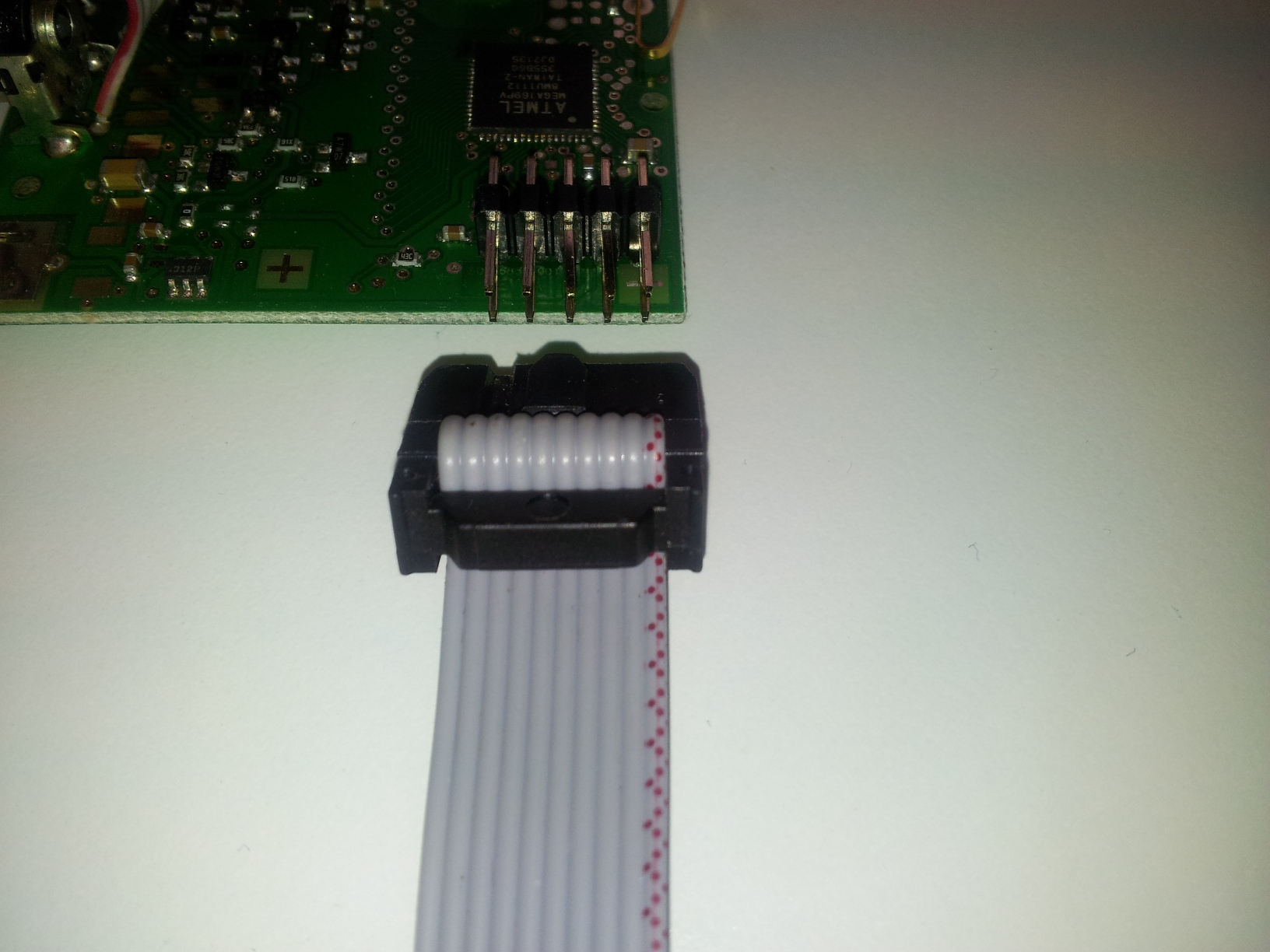
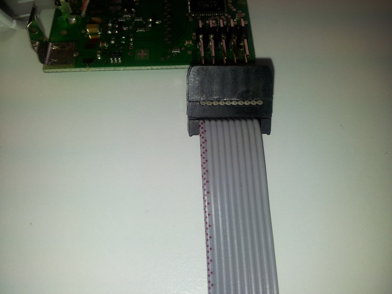


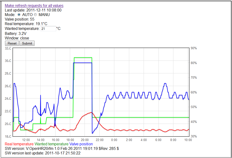
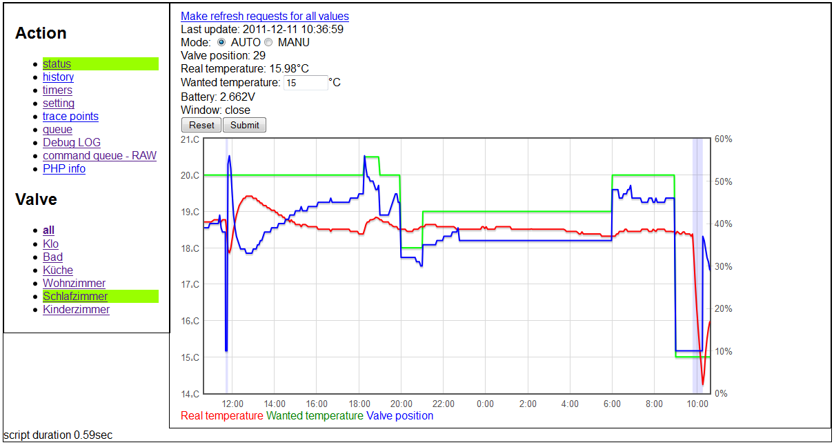
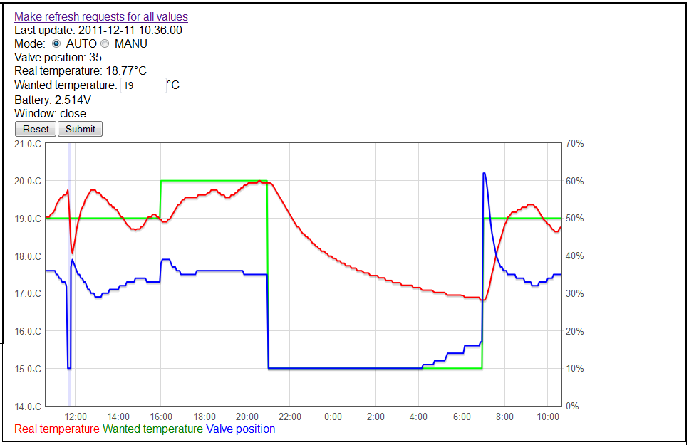

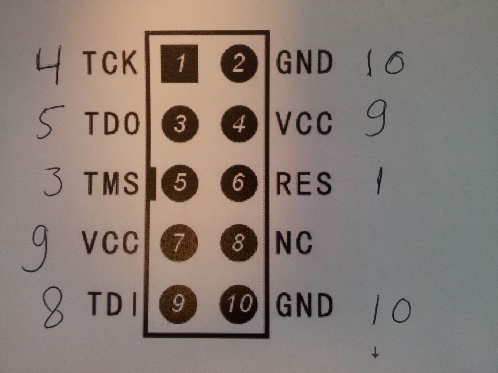

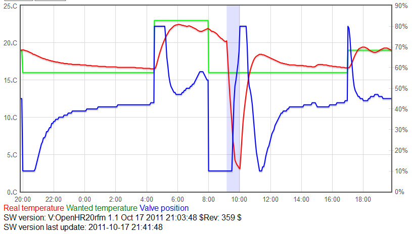


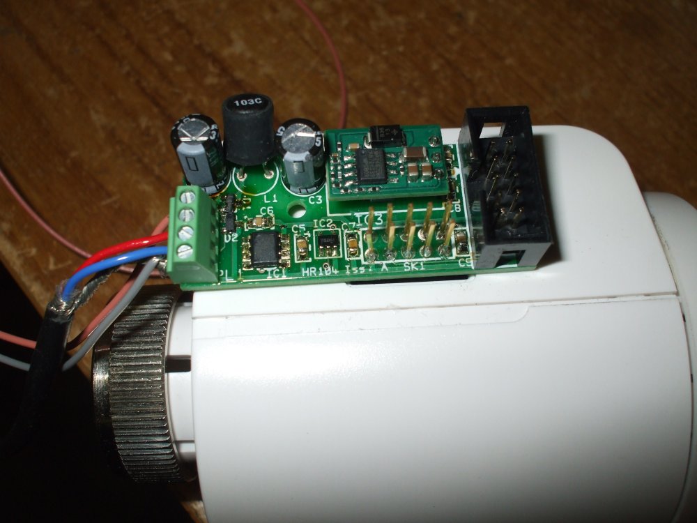


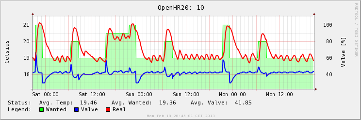


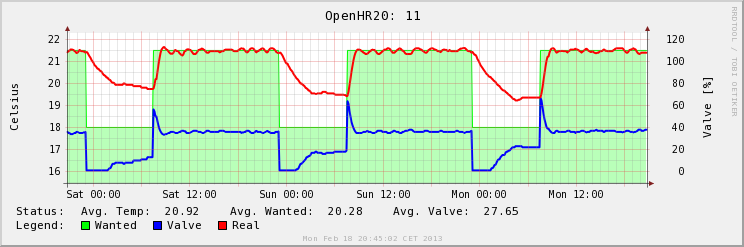
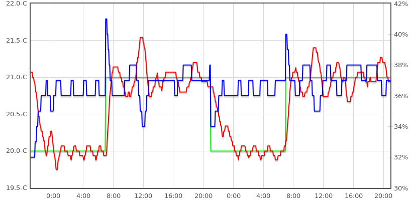