@Jens: I use also constants. But assembler is not my best friend. ;-) So
i used the infomations from the pdf.

@jdobry: It's not a problem. I bought my HR20 in 2010. Now I found the
time to modify it... :-o

@the Problem: You both shift the single bytes and put the carry to the
next byte and that not in the normal direktion... :-o But in the pdf
(http://csrc.nist.gov/publications/nistpubs/800-38B/SP_800-38B.pdf) it's
a normal left shift over all 64bit. So I think it's wrong what you
doing!?

@Wojtek: I'm using this code and wiring: http://www.hs-coburg.de/20775.3
On the HR20 no Softwarechanges needed - but the master must run on the
raspberry - that's what i'm working on.
hey guys,
I don't think that I have understood were you expect to have problem.

Currently I'am running the original HR20 firmware together with an
selfmade server on Cortex-M3 basis. The encryption that I have taken for
the master is somewhere from the internet and is coded in plain C. The
communication works, which lead me to the conclusion that everything is
fine in the asm implementation of jdobry.

A part of my files is taken from here:
http://armcryptolib.das-labor.org/trac

I don't know where the other part comes from, so I simply attached the
files for reference.

When you say there is a problem in encryption, will the communication
not work at all or will it stop working only in some cases?
Hi Star Keeper,

cmac and xtea not the problem. My "problem" is only the generation from
K1 and K2. The security.pdf told me, that i have to left shift the whole
L. But Jiri and Jens making not only a left shift. Take a look at the
sourcecode from Jens (see his post from 2012-12-20) and compare it with
capter 6.1 from this pdf:
http://csrc.nist.gov/publications/nistpubs/800-38B/SP_800-38B.pdf (it's
a link from Jiri)

But in the reality it don't care. I have implemented it in my program
like Jens in his sourcecode. Now my Program on the raspberry generate
the same K1 und K2 like the HR20. It's working. :-)

Another question: I think, i have to acknowledge the data that my HR20
is sending every minute. Because it's already the same dataset and every
4 minute is a new set attached. But what format is the acknowledge? Only
an empty Packet from Master to HR20 with length=0 and without cmac or
anything?

Greets,
Michael
Hey folks, I just stumbled upon this project (after fiddling with ELV
Max! thermostats for a bit, but I need a bit more control) and it seems
perfect for my use. I'll be using a HR-25 thermostat and I'm going to
try to attach it to a 802.15.4 mesh network. If I get anywhere, I'll
post updates here :-)

However, I was looking at the code in svn and looked around the trunk
for quite a while, until I found out the rmfsrc part of the repository.
It looks like the trunk is no longer developed and all new commits
happen on the rfmsrc part, is that correct? If so, wouldn't it make
sense to drop the current trunk (or move it to some branch) and then
make the current rfmsrc directory the new trunk?
Hi Matthijs,
welcome to the HR community :-).
I would recommend to also have a look at Bruce's git repo
(https://github.com/bruce33/openhr20), which contains some improvements
and bugfixes over the svn version. I think it's now the de-facto master
repository.
That being said, the git repo still has the same layout as the svn one,
so it does not really responds to your concern. I agree that some code
reorganization and repo cleanup would help. Removing the old trunk and
replacing it by a branch or tag would be probably a good starting point.
I believe the current status may be related to the fact that noone
claimed the git to be officially the master one, and doing any
reorganisation if there is even the slightest chance of someone merging
the changes back to svn sounds like an integrators nightmare.

So maybe it's a good time to start a discussion - can we consider bruces
git repo as a new master and abandon the svn repo (making it read-only
and reflecting the change in documentation and web pages)?
Oeh, a git repo? Didn't see that one yet. I for one would welcome a git
repository over an SVN repo anytime :-D Making it the official one would
make sense to me, but like you say that really requires deprecating the
old repo and pointing it to the new one to prevent confusing. Given that
the SF project doesn't really contain anything other than the SVN repo,
I'd say it makes sense to use github for the entire project, including
the issue tracker?
Exactly, and I would even go a bit further, e.g. I find quite difficult
to find interesting stuff in this single-thread forum. So maybe even
moving into dedicated discussion forum with actual threading and
sections could be a benefit.
But that needs approval and action from current maintainers, which have
rights to the current svn repo, to the wiki, etc. That's why I initiated
this discussion (I was planning to do it for a long time, but your post
was a good trigger for me ;-) ).
I hope they find the time to respond and give us their opinion.
I noticed a possible bug: When the motor is running and I press the
middle button to view valve position, it sometimes does not react. When
I press several times, it resets (all lcd segments on, asks for
date/time).
Chris wrote:> I noticed a possible bug: When the motor is running and I press the> middle button to view valve position, it sometimes does not react. When> I press several times, it resets (all lcd segments on, asks for> date/time).
Hi Chris,
I tried to reproduce the reset on my unit, but were not successful. Is
it reproducible on yours? Can you give me better description of the
steps to reproduce? What is your HW/SW configuration? If you have added
RFM module, are you sure that your soldering is 100%, i.e. it can't be
HW issue because of mechanical stress caused by the button press? If you
have more units, can you reproduce the same on different unit?
Tomas
I just got two HR-25's today. Haven't powered them up yet, but did pull
one apart to see its insides :-)

Since it was a bit tricky to open up, I thought it would be nice to make
some notes. I also took pictures of its insides.

When opening up, these are the steps to follow:
 - Open up the battery compartment using two knobs at the sides near the
valve end of the unit (also documented in the manual).
 - Pull up both of the knobs from the case. Both knows connect to a pin,
and both pins are connected to eachother in the middle. Just pull the
knobs, or wedge a screwdriver behind them to pull them apart and out of
the case.
 - Pull off the main dial at the front. Just grab it and pull.
 - In the battery compartment at the back and behind the dial at the
front are two plastic clips keeping the top cover in place. Using a
screwdriver, press those to release the top cover.

You can now see the PCB. To pull that one out as well:
 - Remove the tiny screw at the top
 - Carefully pull out the PCB halfway. Note the gold-colored prong at
the top right of the PCB (which normally slightly sticks out into the
battery compartement). If you pull the PCB, it will likely snag against
the chassic. Just press it down a tiny bit so it can slide alongside the
PCB on the bottom of the plastic rail that supports the PCB.
 - The wires to the motor are too short to pull it out completely, so
the motor needs to be removed too.
 - The motor is secured to the chassis using clips on the black plastic
frame. Underneath the PCB you can see one of these clips, the other two
are accessible through the rectangular holes in the battery compartment
(use a screwdriver or something like that to get them loose).
 - Now pull out both the motor and the PCB.
 - When pulling out the motor, make sure you only pull out the motor and
the white gear. There are number of black gears, which are best left
inside (though if you accidentally pull them out, take all four of them
apart and put them back one by one, two on each pin in the chassis).

I also took a load of pictures from the inside of the HR-25, which are
available here:
http://www.flickr.com/photos/46098841@N04/sets/72157636325061713/
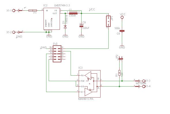
I´ve build a RS-485 interface with a 3,3 volt step down converter for
the HR20.

It uses pin PE2 to switch the send/receive pin.

It works for me just with a little change of the openhr20 software.

I also have a schematic and layout for a RS232 - RS485 converter which i
use to access my hr20 valves.


regards   uwe
Hi,

I'm new to OpenHR, but this all seems to be great stuff!

@Michael R.: Did you manage to run master on Raspberry Pi? I have a
Raspberry Pi running as Server, so it would be great to use it also as a
master vor OpenHR.
Hi,

no - after 2 days, i have given up. It takes a whole of time, to read
the protocol out of the sourcecode. So I have redesigned the master PCB
(smaller then the old one and without an layout bug) and now i'm waiting
for the delivery of the pcb's. I think, it's the easiest way. The winter
is in front of the door. ;-)

Greets,
Michael
@B0B81:

I did following:

1. I switched the "send" functions from the HR20 off.
    Now nothing is send when there´s no order.

2. I give every HR20 a number

3. In the receive function, the HR20 is checking the number
    (first received byte), if it is different:  do nothing.

4. When the HR20 answers, the first byte is his number.


I control the hr20s with a plc but i think this makes no difference.


Regards  Uwe
@Thomas:
I could not reproduce it either with the currect firmware revision. It
seems I used an outdated version or "strange" eeprom settings.

Btw: To get my rooms to the right temperature, I have to set 05:d0 and
06:70 (P3 and P factor). This seems to be far too high. But with the
default settings, the vents are around 50-60% and rooms do not reach
20°C. I think this is because the water is only warm enough to reach the
desired temperature when the valves are fully open.

Another question: Can I run the rondostates at 5V or even up to 5,5V?

Chris
Chris wrote:> Another question: Can I run the rondostates at 5V or even up to 5,5V?
I would not recommend it. As far as I was able to find, most components
have maximum rating over 5V (atmel CPU 5.5V, RFM12B 6V, motor 6V, I
don't know about the LCD), so you may not fry it, but it is still way
over the level recommended in the spec sheets, so I would be surprised
if everything worked as you expect.
If you have a 5V source you need to use, perhaps it's easiest to just
add a 3.3V regulator? As a bonus, you get a nicely regulated voltage
instead of just whatever the battery cares to provide like the normal
circuit has...
avrdude: verification error, first mismatch at byte 0x0015
99
0x21 != 0x00
100
avrdude: verification error; content mismatch
101
102
avrdude: safemode: Fuses OK
103
104
avrdude done. Thank you.
105
106
*** done!
After that I was unable to flash anymore because avrdude complained
about my Signature 0xffffff.

I stumbled over a post http://embdev.net/topic/118781#3112836 from Frank
where he has gotten the same Problems.

So I conected Reset to Ground an I was able to flash the device

Now I get this Message:
1
sebastian@sebastian-SX20S:~/openhr20/rfmsrc/OpenHR20$ sudo ./flash_hr20.sh*** making backup...
2
*** backing up fuses...
3
4
avrdude: AVR device initialized and ready to accept instructions
It seams that I managed to flash everthing in the right way.
But after installing the master and the rfm-12b I keep getting Error E4.

daemon.php writes following lines:
1
O0000
2
< OK
3
< d1 11.11.13 14:27:00
4
< RTC?
5
H0e1b0000
6
Y0d0b0b
7
< (01)?
8
< OK
9
< OK
10
< (02)?
11
< (03)?
12
< (04)?
13
< (05)?
14
< (06)?
15
< (07)?
16
< (08)?
17
< (09)?
18
< (0a)?
19
< (0b)?
20
< (0c)?
21
< (0d)?
22
< (0e)?
23
< (0f)?
24
< (10)?
25
< (11)?
26
< (12)?
27
< (13)?
28
< (14)?
29
< (15)?
30
< (16)?
31
< (17)?
32
< (18)?
33
< (19)?
34
< (1a)?
35
< (1b)?
36
< (1c)?
37
< (1d)?
38
< N1?
39
O0000
40
< OK
41
< d1 11.11.13 14:27:30
How can I control if both master and OpenHR are functioning well?
Hi,

I tried to send serial data to 4 rondostates running the openhr20
firmware. It only worked with one of them until I used 1200 baud instead
of 9600 baud.

So I'm asking myself: Why does openhr20 use 9600 baud by default? There
is not much data to be transfered, so lower baud rates would be
sufficent and less prone to clock derivations of the rondostate's
internal osc.
Hi,
the idea behind the baud rate setting is that faster baud rate means
less time needed to transfer all the data required, thus less battery
power used for transmit. But it also means, as you noticed, less robust
communication and smaller range. So you need to find the setting that
works best for your installation.
problem is internal oscilator in ATMEGA chip. It is possible calibrate.
One way for calibration is use 32768Hz xtal inside HR20. But I has not
flash space for this code. Another way is calibrate it manually.
Do you think that lousy AVR oscillator can affect wireless
communication? If yes, how?
RFM12 has its own oscillator, which should be better, so IMHO only
bit-banging SPI communication can be affected. Am I overlooking
something?
Wireless communication have 2 clock sources. 10MHz xtal on module for
radio transmition frequency. It run only during RX/TX to save energy.
HR20 use 32768Hz for real time clock and same timing source is used for
wireless packet time slots.
MCU use internal RC for processor clock and RS232. It is enabled only
when needed to save energy.
Yes. I connected an external atmega8 which is powered by the hr20 and
receives the serial data. There are other sensors involved (humidity,
window ...) so I needed the extra controller. I'm using a ceramic
oscilator... could that be done with the hr20, too?
I had some timing issues with RS-232 during debugging as well. I had
changed the UART setting to use normal speed instead of double speed (by
removing the setting of U2X bit in UCSR0A and changing the UBRR divisor
to 16 from 8 in rs232_485_hw.c) and the issues seems to be resolved. You
may want to try that as well, Chris, maybe it will help you too.
Does anyone know why the double speed was chosen as default? Any
particular reason, or just a coincidence? :-).
Thanks Thomas for the app note, this is very interesting!
Not shure about the double speed. Maybe it saves power? If so, it must
be very little....

I just implemented the following solution, which looks promising so far:
On power up, my extension board starts with 8000 baud. It then sends
"V\n" to the rondostat while increasing the baudrate until it reaches
13000 baud.
The answers of the rondostat are received and the center of the lowest
and highest working baudrate (rondostat answers with "V:Open"...) is the
correct baudrate.
So far, this works great and takes only 5 to 10 seconds. I could speed
that up with an more inteligent approach instead of dully stepping up
the baudrate, but there is no need to to that.

Btw: The baudrate of my 9 rondostates is between 8600 and 12900 baud. No
wonder this causes trouble.....

Another thing I noticed: I actually have to send "V\nV\nV\n" to get an
response. It seems the rondostat needs to be forced awake before it
interprets commands.... ?
I thought I got a good deal on RFM12b radio modules, but it turned out
they are the newer RFM69CW. Supposedly the footprint is compatible, but
the software is different. They also apparently have some other
advantages over RFM12b e.g. range & encryption.

Any views on whether it's worth trying to add support for these radios
to the codebase? If not, I'll stick them back on eBay.

Rhys
As RFM12B is being phased out (AFAIK hoperf promised they will keep
manufacturing it for the time being, but it's not recommended for new
designs) it would make sense to start experimenting with newer types. So
I would say go for it, if you have the time :-).
This might be of interest if you decide to start on it:
https://github.com/LowPowerLab/RFM69
I have exactly the same problem as reported by BOB 81 on 11-11: code E4
on the thermostat. And no responses from thermostat when running
daemon.php

How to check which part is at fault?

BOB, did you manage to solve your problem?

Thanks!
Sorry, I should probably add that I am following pointec's tutorials (
see here: http://piontecsmumble.wordpress.com/?s=openhr20 ) with an
Arduino Uno and control over RFM12b. The Arduino's RX and TX LED's are
actually flashing while running daemon.php, so that gives some (if very
slim) confidence that the master side is working.
Well, I managed to figure out that I had some pins wrongly connected.
Now I do get values back from the thermostat. Great!

I do however get error messages when running daemon.php (I temporarily
set all debug statements to true).

Can somebody tell me what this error means? Thanks!
If you are getting ERRxx message it means that there is an error :-).
First, make sure that you have your thermostat close to the master to
rule out communication problems. Next, make sure that your crypto key is
the same in master and in the thermostat (please be aware if you are
flashing your arduino master via arduino style bootloader, you can't
flash eeprom, where the keys are stored, you need to use serial console
to set the key or update the whole eeprom. I spent few days figuring
this out ;-) ).
If this does not help, I will think a bit more :-).
Tomas Kopal, Thanks for the hints. I've rechecked the encryption keys.
But these are absolutely identical. Note, I did have some communication
already working. I thus simply continued following pointec's articles.
And in fact I managed to get everything working. So I must say that the
errors are not bothering me (too) much. However, of course they should
not be there. And if it is helpful for the project if I test some more,
then I'm happy to that.

One other thing I wonder: Did anybody think of cutting the HR20
thermistor and then remounting it using wires at some distance away from
the unit, such that the measured temperature is more representative for
the room? Did anybody do this? It seems to me that it could allow more
realistic/accurate setpoints. However, I imagine that it would require
some adjustments to the default control settings? Would it also require
some changes to the code on the unit? Or should this simply work?

Thanks for a great project!
@BOB: I accidentally swapped two wires on the Arduino/RFM12b wiring.
Simply my fault. I have it working now exactly following pointec's
article part 4 (despite a few errors on the serial console). I also
restarted the thermostats a few times (reinserting the batteries), but
I'm not sure if that's really required.
something is wrong with xtea calculation.
during the crypto_init with same values (Default key 0x01 0x23 0x45 0x67
0x89 0xab 0xcd 0xef) the master code returns 0x3b d6 f1 a6 ac 20 b2 b4
(for k_mac first step) but the hr20 code Returns e2 57 7e 26 de 63 d0 54

whats wrong ? the K_m value is the same but different values are
calculated. I checked the lss files and its look fine, so its the same
function inside...

the code is same the values and fuction also, only one Thing is
different the master is 328P ... but it should be not a Problem.

Any idea ? maybe somebody can check what is the right value ?
(xtea_enc(K_mac, K_mac, K_m); /* generate K_mac low 8 bytes */)
Wavemaker wrote:> Tomas Kopal, Thanks for the hints. I've rechecked the encryption keys.> But these are absolutely identical. Note, I did have some communication> already working. I thus simply continued following pointec's articles.> And in fact I managed to get everything working. So I must say that the> errors are not bothering me (too) much. However, of course they should> not be there. And if it is helpful for the project if I test some more,> then I'm happy to that.
Ahh, I thought that you were getting errors but no communication. In
case your communication is working, and you are getting these errors at
random times, it just means there is some interference with other
transmitters (cordless phones, alarms, microwave owen...) being
interpreted as having valid preamble by your RFM12. But the
encryption/crc check will take care of that, so you can safely ignore
that. It just means more processing by the MCU, so a bit more battery
wasted. If you are getting too many of these, you can try tuning your
radio to different frequency. But without some analyzer, it's mostly
trial and error game...
> One other thing I wonder: Did anybody think of cutting the HR20> thermistor and then remounting it using wires at some distance away from> the unit, such that the measured temperature is more representative for> the room? Did anybody do this? It seems to me that it could allow more> realistic/accurate setpoints. However, I imagine that it would require> some adjustments to the default control settings? Would it also require> some changes to the code on the unit? Or should this simply work?
I haven't tried, but I suppose that long wires will not do much good to
the precision of the thermistor. I think that better option is to use
dedicated thermometer with it's own wireless transmitter, or or even
wired to master, but I do not think this is supported by the master sw
at this time.
Wojtek Sim wrote:> something is wrong with xtea calculation.> during the crypto_init with same values (Default key 0x01 0x23 0x45 0x67> 0x89 0xab 0xcd 0xef) the master code returns 0x3b d6 f1 a6 ac 20 b2 b4> (for k_mac first step) but the hr20 code Returns e2 57 7e 26 de 63 d0 54>> whats wrong ? the K_m value is the same but different values are> calculated. I checked the lss files and its look fine, so its the same> function inside...>> the code is same the values and fuction also, only one Thing is> different the master is 328P ... but it should be not a Problem.>> Any idea ? maybe somebody can check what is the right value ?> (xtea_enc(K_mac, K_mac, K_m); /* generate K_mac low 8 bytes */)
I am also using 328P in the master, and with the default keys
communication works. So it is not MCU specific, I guess. Check your
compiler flags, maybe some signed/unsigned problem?
@Tomas
thx for the hints, I checked the Compiler Options and signed/usinged
values
there is no differece :-( I think these will be visible in lss file, due
to the Assembler code is already inside. but there is no "big"
differences
Only one Point is different but it should be not a Problem (the
xtea_enc(K1, K1, K_mac)call, one time call(master) is unsed one time
recall(HR20), but the jump adress is fine)

maybe there is a Problem with other Thing like static,const or ISR
routines. Have no better idea :-(

maybe my modifications for 328P caused this strange behaviour.
did you download the master 328P code, I did not found the branch for
328P.

BR
Wojtek
Wojtek Sim wrote:> @Tomas> maybe my modifications for 328P caused this strange behaviour.> did you download the master 328P code, I did not found the branch for> 328P.
If you want to take a look at my version, it is here:
https://github.com/KickerTom/openhr20. It is a fork of Bruce's code, but
not all changes are merged back there yet. Hope this helps, good luck.
Here is my master configuration report:
Configuration
Hardware type: MCU atmega328p at 16000000Hz
RFMFLAGS=-DRFM_TUNING=1 -DSECURITY_KEY_0=0x01 -DSECURITY_KEY_1=0x23
-DSECURITY_KEY_2=0x45 -DSECURITY_KEY_3=0x67 -DSECURITY_KEY_4=0x89
-DSECURITY_KEY_5=0x01 -DSECURITY_KEY_6=0x23 -DSECURITY_KEY_7=0x45
-DRFM_FREQ_MAIN=433 -DRFM_FREQ_FINE=0.35 -DRFM_BAUD_RATE=19200
MASTERFLAGS=-DNANODE=0 -DJEENODE=1
==================================
AVR Memory Usage
----------------
Device: atmega328p
Program: 7660 bytes (23.4% Full)
(.text + .data + .bootloader)
Data: 1169 bytes (57.1% Full)
(.data + .bss + .noinit)
EEPROM: 104 bytes (10.2% Full)
(.eeprom)
@Tomas
thx a lot, it works :-) at least the keys calculation (xtea calls) works
correctly
I am using the audrino uno board, so some changes of RFM12 connectors
will be needed to get the master running. Have no much time now, but I
will try to found out what was the Problem with my code.

Thank You!
master is running :-) thx a lot to all again!
Now I am looking for a GUI or logger for the data received by the
master.
(for hr20 controller tuning) At the Moment I am using hyperterminal :-(
I found some info about rrd and open router SW (additional hardware) and
for Linux os (?)
I would like to use my WIN7 PC for that, any hint and experience ?
BR
Hello All, Tomas,

Just as feedback, I wanted to mention that as an experiment I did cut
the thermistor on my thermostat and reconnected using wires at a
distance of approximately 1 m. The purpose was to measure a temperature
closer to the average room temperature. I did have some issues with
false open window detections. However, after effectively switching that
off (see higher up in this thread), everything seems to work nicely.

Also some tips that others may find useful: I experienced occasional
corruptions of the sqlite database when the server's daemon.php is
closed uncleanly.
- One issue was with error messages saying that the database is
"malformed". The following solves this (rebuilds the database):
echo ".dump"|/usr/bin/sqlite3 $DB|/usr/bin/sqlite3 "${DB}-tmp"
- Also occasionally I got messages about missing tables. This is easy to
fix. The create_db.php script can be easily rewritten to create any
table that does not exist anymore: "CREATE TABLE IF NOT EXISTS"
First of all, I want to thank all involved for creating this outstanding
firmware ;)

2nd, some Infos regarding JTAG, Linux, Rodostat HR-20 Style etc.

I spent the weekend testing 3 devices of above type.

Since I'm on Linux and own only a generic FT2232H JTAG interface (Olimex
ARM-USB-OCD-H), I had trouble flashing the firmware:
avrdude didn't work, since the built-in FT2232HIO driver works in
ISP-Mode only (and I didn't want to solder each device).

I looked around and could not find a way to program the devices via JTAG
only. The Atmel programmers and their clones seem to be the only way
when avrdude is involved.
OpenOCD does have some support for ATmega128, but it is very basic and
looks abandoned. Also, no obvoius way to change the fuses....
After some google-foo, i found some info about "jam" and "svf" formats,
which could be played back via OpenOCD and used for programming fuses,
flash and eeprom (since they basically wiggle the pins and that's it).

Most relevant page is http://www.awce.com/avrjtag.htm (download
included).

I didn't find a hint of info on Atmel's web site about avrsvf....

So, I did the following:

1.) Compile OpenHR20 as needed.

2.) Use avrsvf (via wine) to generate an svf file for erasing + changing
the fuses:
The above options basically means:
- produce heavily commented svf output
- check the device signature first (otherwise svf aborts)
- !!!! erase the device !!!!
- set the 3 fuse bytes (ex, hi, lo) to 0xFF9BE2
- verify the fuse bytes (otherwise svf aborts)
- output file hr20-fuses.svf

There seems to be an no longer maintained cross-platform tool for this:
http://sourceforge.net/projects/avrsvf0/
But it does not support ATmega169P and I didn't want to take any
chances.
Customizing may be possible, if Atmel didn't reinvent the wheel with
different controllers and JTAG...

3.) Use avrsvf to generate a svf with erasure, fuses, flash and eeprom
contents:
The above options basically means:
- see 2.)
- program eeprom and flash
- verify eeprom and flash
- output file hr20.svf

4.) Connect via openocd + JTAG-dongle to the device. Set up a telnet
port (4444) for a cli interface. My hr20.cfg for openocd:
Above code is stolen from avr-target config of OpenOCD, only _CPUTAPID
and the tap config was customized.
The flash part is optional, as is most of the config ;) Basically, you
only need:
- adapter_khz
- reset_config
- adapter_nsrst_delay
- jtag newtap statement with irlen, expected-id

4.) Connect via
1
telnet localhost 444
to openocd, execute:
1
svf hr20-fuses.svf
2
svf hr20.svf
... and watch a few thousand JTAG-statements getting executed.
I did set only 0,5MHz JTAG speed, but it thould take <10s to flash (or
error out). I had trouble getting 4,5MHz (from original avr OpenOCD
config) to work, verifying the flash failed, but fuses where fine.

Conclusion:
The above should be a generic guide to flashing all types of AVR MCUs
via JTAG and OpenOCD and should basically be cross-platform, except the
usage of avrsvf.
So, it is possible to live without avrdude ;)

Caveats encountered:
A) Setting fuses only works after erasing the device.
   A reset is needed in between, easiest way was 2 svf scripts.
B) My HR-20 Style have an Atmel ATmega128PV MCU (note the P!!), which
   has 3 fuse bytes. All existing bytes need to be set with avrsvf.
C) ATmega128(V) and ATmega128P(V) have the same JTAG signature,
   but setting fuses works only when the correct type is selected
   Needed some time to realize this, a real "doh!" moment....
D) avrsvf is Windows-only, but has a config file which may enable new
   types of MCUs and has no dependencies at all so i deemed it well
   worth the wine hassle..
E) SVF files seem pretty simple, it may be possible to create a
   template which sets up the flash and insert hex/eeprom contents
   into it. May be some evil shell-script hackery, but since *.hex
   and *.eep are already in hexadecimal it should not bee to difficult
   to hack some "SDR 15 TDI($VALUE);" around it...

Hope this helps.

Question: Is there a user manual for the OpenHR20 firmware somewhere
around? I was able to map all functionality (I hope), but it seemed odd
that not a single readme documenting the new functionality was around.


TL;DR: My HR-20 Style work fine now, thanks a lot.
LOL wrote:> Question: Is there a user manual for the OpenHR20 firmware somewhere> around? I was able to map all functionality (I hope), but it seemed odd> that not a single readme documenting the new functionality was around.
None that I would be aware of. I also had to find all the functionality
by reading the code.
Hi,

one question, i downloaded the HR20.hex and HR20.EEP from /trunk/source
from svn.code and flashed the hex-file, this works. but the .eep file
cannot be flashed, because it seems to be to big, my programm says "file
is too large to fit into buffer". and without flashing the .eep file,
the HR20 shows "EEPr" on the LCD. i read the code, and it's because of
checking the eeprom-layout at start-up, and i can not flash the .eep
file.

how did you flash the .eep file? is there another .eep file?

and: did someone have the original software for the HR20. i downloaded
it before i flash the new software, but i didnt work after flashing the
old software.

thanks

Jan
Jan Wmann wrote:> Hi,>> one question, i downloaded the HR20.hex and HR20.EEP from /trunk/source> from svn.code and flashed the hex-file, this works. but the .eep file> cannot be flashed, because it seems to be to big, my programm says "file> is too large to fit into buffer". and without flashing the .eep file,> the HR20 shows "EEPr" on the LCD. i read the code, and it's because of> checking the eeprom-layout at start-up, and i can not flash the .eep> file.
Hi
what tools are you using to flash the eep file? For me, using JTAG and
Atmel Studio, it works just fine (mind you, it's with self-built files,
I never tried flashing the pre-built one, but I suppose it should be
ok).
You definitely want that flashed, the firmware won't work without it.
>> how did you flash the .eep file? is there another .eep file?>> and: did someone have the original software for the HR20. i downloaded> it before i flash the new software, but i didnt work after flashing the> old software.>> thanks>> Jan
As far as I know, there is no way to get back to the original firmware,
the MCU has a no-read fuse set, so you can't extract the original
firmware from it. So no, I do not have it and I doubt anyone else have
it. Once you flash the MCU, you are on your own, there is no way back.
Thank you,

i try to flash the hex and eep file with bascom, where flashing the
hex-file successfully worked.

due to your anwser i tried it with atmel studio 6 and AVRISP MKII, but
the studio does not know the chip "atmega169". it only knows
atmega169A,P and PA. it dosn't work with one of these chips.
faultmessage "unable to enter programming mode" appears.

Can i add another controllers to atmel studio 6? or do you have another
idea?

thank you

Jan
Jan Wmann wrote:> due to your anwser i tried it with atmel studio 6 and AVRISP MKII, but> the studio does not know the chip "atmega169". it only knows> atmega169A,P and PA. it dosn't work with one of these chips.> faultmessage "unable to enter programming mode" appears.
Wait, AVRISP MKII ? That is ISP programmer only, isn't it? How did you
connect it?
Rondostat thermostats needs to be programmed via JTAG, which is wired to
the connector. ISP lines are used for other purposes, and I think (but I
may be wrong, I haven't really checked or tried) they are unusable for
ISP programming...
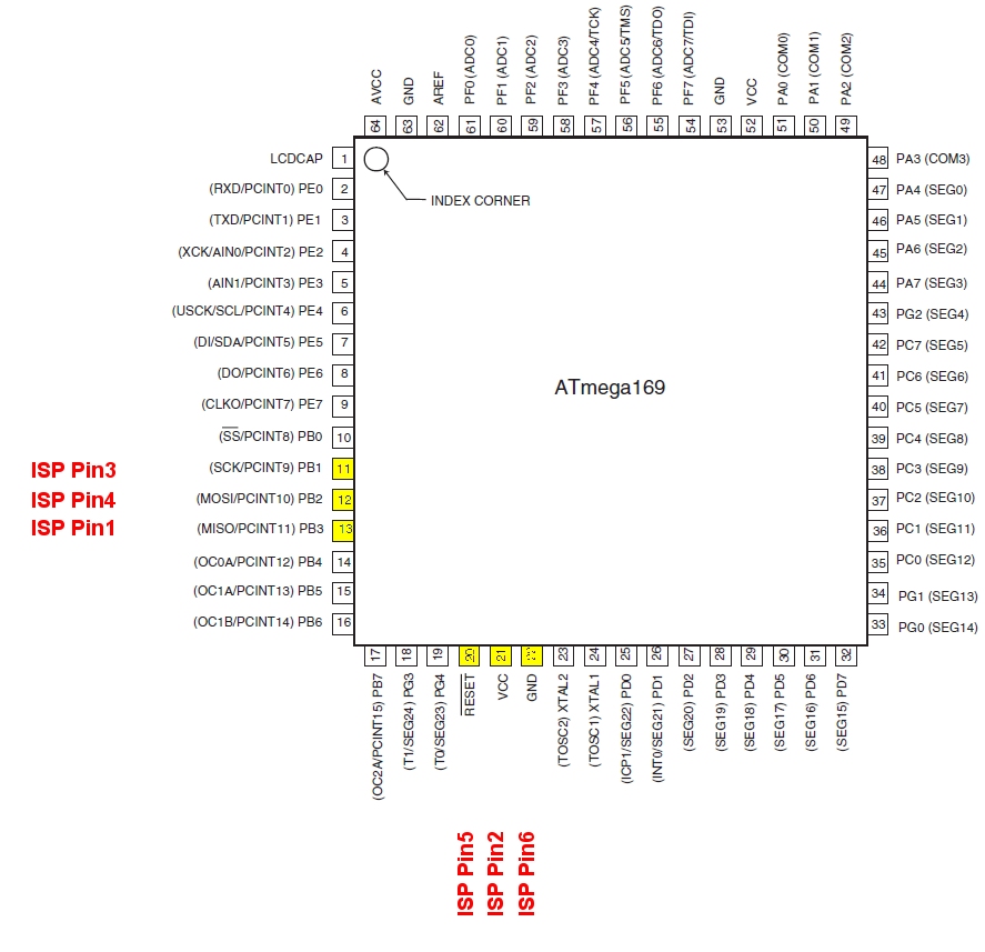
yes, i programm with isp. have soldered a programmer to RESET, VOLTAGE
and GROUND at the connector and MISO, MOSI and SCK to the switches
(prog, auto/man,etc). and with bascom and the bascomprogrammer it works
good.

tomorrow i will test with the EESAVE fuse. the wiring musst me correct
due to the fact that i can programm it with the other isp-programmer.

thank you

Jan
so, shame on me  :-)

now it works, and the problem was, that i had from my last project the
isp-speed to high. i set the isp-speed to 125kHz and now it works.

thanks to you for your help

Jan
jdobry wrote:> About PID controler:> You are right it NOT use "D". Reason is simple. It is compromise between> battery life and response time. Without "D" it is bit slower, but wit> longer battery life (less actions).>> It contain one trick in PID. For "P" it not use error value direcly but> use error^3.
I set this so called "PP" to 0, because it makes no sense. The reason
is, that you need much more power with this setting, battery as well as
"Oil".
The problem with that value is, that it opens the valve and closes it
completely. That needs mach more Battery than just open the valve a
little bit to mouch.
The second problem: if you open the valve completely, it's hard to find
out when the heating more than needed. In my flat, most if the time the
temperature was much to high after that. And my old syle analogue energy
counters are very sensible to high tempuerates at the radiator.
I recommend to set this value top zero and tune the I and P values, so
that P heats a little bit more than needed, and I should be not to high.
I have problems compiling openhr20 with newer versions of gcc. On debian
squeeze I have gcc-avr 4.3.5 on debian wheezy I have 4.7.2.

The eeprom alignment differs between these versions:
in bin/HR20_rfm_int_sww/hr20.map i get with 4.3.5:
Hey folks,

the OpenHR20 project has moved and is getting new maintainers. We're
moving to github for the code and Google Groups for discussion. If
you're still interested in the project, make sure you subscribe to the
new list / forum and perhaps also to the github project.

For more info, see this post on the new group:
https://groups.google.com/d/msg/openhr20-development/NMD_Un5_aCc/AO4AJFlR_AgJ
good afternoon gentlemens.

I just came across your great work and I am very impressed by the job
done.

I use MySensors for home automation. http://www.mysensors.org/
These are sensors and actuators based on arduino  + NRF24L01 for radio
communication.

Do you think it would be doable to insert a NRF24 module inside the HR25
casing ? Communication is done over SPI, so the wiring should be similar
to the RFM12.

Would it be doable to flash the atmel MCU with an arduino sketch ?

What do you think ?
Hi,
I haven't tried, but I think there is no inherent problem in using NRF24
module instead of RFM12B. It should even fit into the thermostat casing,
there is plenty of space in there. Not sure what range you would get,
and what would be the power consumption though.
Wiring should be similar, except NRF24 has a dedicated IRQ line and two
chip enable signals instead of one. But I think that should be solvable.
The biggest problem would be the software. Control of NRF24 is, I think,
completely different to what RFM12B expects, so you would have to
rewrite that part in OpenHR. I tried making the RFM code a bit more
separated, trying to use RFM69, but I haven't got too far (yet). It's
doable I think, but it depends on how much time you want to spend on
this (and on your experience with embedded SW).
I am not sure what you mean by flashing atmel MCU with arduion sketch?
Like programming the thermostat via arduino IDE? Possible, but I would
not recommend it. The flash in HR20 is quite packed with OpenHR sw,
which is quite size-optimized. I think that similar functionality won't
fit when implemented in Arduino framework. (HR25 has more flash, so the
situation is different there.) Also, OpenHR is not using Arduino
framework, so you would have to rewrite the whole thing. More work than
adding NRF24 support to OpenHR, IMHO.
Also, I am not sure what exactly you want to achieve. Usually, generic
systems for home automation are not very well suited to control the
whole network of thermostatic valves IMHO, looks like micromanaging to
me. I would probably look more to build the system with some central
unit, as OpenHR currently does with its master, and then connect this
central unit to the home automation system. But YMMV :-).
Thanks for your answer.

I would like to program with arduino IDE because i am more confortable
with it and the communications library for MySensors have been
develloped for Arduino.
I would do my test with a HR25, so, i would benefit of the extra
flash/ram.... But anyway, i dont't think the Atmega329 is natively
supported by arduino IDE. There is probably some tweaking necessary to
use it with arduino.
I don't recoment develop SW like this in arduino platform.
Arduino is nice toy for rapid development. But this cause some
limitations and block some advanced technics. For example power
management to work 1-3years with one battery set.
Good evening
I've been using openhr20 with 10 hr20's for about 2 months with great
success but migrated the whole thing to a new raspberry pi, was using it
on a slightly older Pi with only 256Mb memory, now i have 512 to play
with for a nice temfs ramdisk.

Problem is all valves communicate and I can see the results in the web
interface but I cannot change anything in the valves ie if I go to the
timers page of a valve and ask "Make refresh requests for all values" it
just immediately returns with "No waiting commands" whereas before it
used to say 115 commands waiting or whatever was in the queue and so all
my timers pages have N/A in all boxes and anything else I try to change
does not get sent to the valves. With php daemon.php running in a
terminal all looks normal just never any commands comming from the web
interface.

I've created a new fresh database restarted everything loads of times
but nothing seems to work.

Has anyone here got any idea what I might be doing wrong.

John
Good morning

Sorry for wasting time.... if I had read my logs error.log in
/var/log/apache2

[Tue Feb 17 06:31:40 2015] [error] [client 192.168.20.71] PHP Warning:
SQLite3::query(): attempt to write a readonly database in
/var/www/boiler/public/hr20/contend/queue.php on line 19, referer:
http://192.168.20.83/hr20/?page=status&addr=10

I would have seen my database had been created as user pi and was read
only to user www-data .... Numpty! ....

Silly me, hope this might help someone who makes the same mistake

John
@Tomas Kopal

Thanks Tomas for your headsup und information and sorry for spoiling the
thread recently...

Piontecs mumble's great documentation proposes the process of using
Linux for the make process...

Unfortunatly, Since i am not very familiar with Linux anymore, i cannot
use It for the make process.
I started using Atmelstudio with JTAGICE some month ago and find it
quite usefull and handy to do devs in a timely manner..
Initially Started with Arduino IDE but for coding more than a few lines
this is not very suitable...

So i would love to do the dev process in AS6.2.
Maybe there is a chance for me to get this started to transfer the files
of the project from Linux make files to As6.2 with some help from you or
other mates. I have seen AS6.2 allows for external makefiles, but i
havent found much info how to use it.

As i already mentioned i'd love to contribute to the project as much as
i can in regards to things i can do - like testing, and once i got some
experience in compiling the sources and documentation the sources and
processes. I have also quite some experience with RF circuitry as i'm a
licensed Radio Amateur - currently just playing around with some newer
RFM modules from Hope.

You mentioned a wiki, which you setup on Github for this project, but i
found no link to it - i'd love to create some info pages there as well.

Kind regards, Mike
Hi @all,

I'm using OpenHR20 firmware quite a while now and I'm very happy with
it. Some time ago I found those ESP8266 low cost WiFi modules which just
need an serial interface. The protocol is quite easy (some AT commands
for configuring and a few for UDP- or TCP-connections). Would it be
possible to modify OpenHR20 firmware to use those WiFi modules directly
attached to the HR20 serial interface?

The problem I see is, how to configure WLAN- and IP-settings. But as a
fitst step it seems sufficient to be, if those things can be configured
in the source before compiling.

Is anyone else intrested in such a feature?

Greets
  Sebastian.
Hi Sebastian,

I don't see any reason why this module should not work with OpenHR,
assuming you adapt the code accordingly (which may not be as simple as
it may sound, as the current RFM code is not very well separated).
Regarding addresses - we already have an address for every unit, which
can be specified while building the firmware, or set later via
engineering menu. I suppose it would be quite easy to adapt to IP
address, "MAC address" for auto-configuration, or revamp the settings
completely and do proper connection setup. Depends only on how much time
you want to spend on this :-).
ESP8266 is nice chip/module
It will work, HR20 have serial line in connector. But don't expect life
time longer than days with batteries. This module is little bit hungry
compare to RFM12 :-)
I would recommend using one of IQRF transceivers (www.iqrf.org)
DCTR-5xDAT. It has very nice framework easy mountable to HR20. You could
use SPI or UART to communicate with HR20. I am now working on connecting
it to HR20.
Milan Musec wrote:> I would recommend using one of IQRF transceivers (www.iqrf.org)> DCTR-5xDAT. It has very nice framework easy mountable to HR20. You could> use SPI or UART to communicate with HR20. I am now working on connecting> it to HR20.
I would be quite interested in your experience with this radio. I had
some bad experience so far with trying to get reliable signal with
antenna inside of the housing (but with different radio, different
antenna, even different frequency), so I wonder what this PCB antenna
can deliver. Also, I would be a bit afraid of power consumption of this
radio module, so any info about real battery lifetime would be nice.
Please keep us posted...
I've managed to build the OpenHR20 firmware and flash an HR20 device
with it. It appears to be working in the sense that I can communicate
with it via the serial port, and it appears to be functioning as
expected when attached to the heater. However, I'm having trouble
setting the timers.

Maybe I don't understand the timer settings, so perhaps someone will be
kind enough to guide me through a simple setting: I want to program all
days (1-7) so that at 6:30 the temperature is set to 21 C, and at 22:30
the temperature is set to 17 C.

This is what I tried:

1. I held the "PROG" button then pressed "PROG" again when "1-7" started
to flash.
2. To set the 6:30 temperature, I pressed the thermometer (middle)
button to select the night/day, then dialed 6:30 and pressed "PROG".
3. To set the 22:30 temperature, I pressed the thermometer button to
select night, then dialed 22:30 and pressed "PROG".
4. For the remaining timers, I dialed "--:--" and pressed "PROG" for
each of them.

However, the second timer (which should read 22:30) stays at 09:00, even
if I attempt to program it by writing over the serial port. In fact, the
only timer I seem to be able to set is the very first timer.

Am I doing something wrong?
I figured out what I did wrong: I had checked out the code repository at
http://sourceforge.net/projects/openhr20/ and it seems to build version
0.99 of the firmware.  However, the compiled binaries that one may
download from Sourceforge appear to be version 1.0, and that version
works.

Where (or how?) do I find source code that is up to date?
Latest sources is in directory RFMSRC.
But some guys fork this project into github and this new fork also
contain some additional fixes. See to this thread history.
Yup, the latest source is now here: https://github.com/OpenHR20/OpenHR20

I still need to update the sourceforge page to point there (but wanted
to clean up some documentation first, but haven't found the time yet so
far...)
Thanks. The current source code on Github doesn't appear to work on my
devices, but I'm not currently in the mood for debugging. The HR20
devices seem to work with the binary of version 1.0, so I'll just
consider it "closed source" for now.
I know what you mean; it's just that as long as I have no idea which
revision of the code it was compiled from, the chance of finding the bug
was introduced becomes somewhat difficult.

EDIT: Strike that. I managed to make it work. Thanks for your help!
FYI,

I just got around to programming the rest of my thermostats, and had to
do the following:

sudo avrdude -p m169 -c dragon_jtag -e -B 12 -U flash:w:hr20.hex
sudo avrdude -p m169 -c dragon_jtag -U hfuse:w:0x99:m
sudo avrdude -p m169 -c dragon_jtag -e -B 12 -U flash:w:hr20.hex -U
eeprom:w:hr20.eep -U hfuse:w:0x91:m

If I didn't flash the hex first, I was not able to set the fuse.
Hello Sebastian,
Found your idea quite intresting.
There is open source framework Sming,provide Smart config option i.e
wifi configuration can be set from any smart phone.
Apart from battery , I do not see any other hurdles.
Here is link for Sming.
https://github.com/SmingHub/Sming/tree/master/Basic_SmartConfig.
Keep posting.
Saurabh
Sebastian C. wrote:> Hi @all,>> I'm using OpenHR20 firmware quite a while now and I'm very happy with> it. Some time ago I found those ESP8266 low cost WiFi modules which just> need an serial interface. The protocol is quite easy (some AT commands> for configuring and a few for UDP- or TCP-connections). Would it be> possible to modify OpenHR20 firmware to use those WiFi modules directly> attached to the HR20 serial interface?>> The problem I see is, how to configure WLAN- and IP-settings. But as a> fitst step it seems sufficient to be, if those things can be configured> in the source before compiling.>> Is anyone else intrested in such a feature?>> Greets> Sebastian.
Good morning,

i love this project. In 2008 to 2009 i worked a little on it. But in
case of little time i stopped work until now.

Last weekend i restarted the work. After some troubles im able to flash
the devices and i build a master.
It looks like that the hardware is working and the software too.

I have some trouble with the master syncronisation.

What i am looking for, is a flow chart or something like that, which
shows the communication between the master and the daemon.php.

Can anyone help me?

Many greetings
Peppe
Hi Peppe,

welcome back :-).

The best description I know of is in repository,
rfmsrc\doc\hr20-security.pdf. If you need more details, I am afraid you
will have to check the source code.

Edit: Sorry, I should have read more carefully, I though you want
communication between master and the units. For the daemon.php, I don't
think there is anything better than the code, sorry.

Tomas
Hi Tomas,

thanks for your answer!

in the meantime i build the master board and i wrote a little java RCp
tool to test the communication.
Until now i am able to send the date and time to my valves. I tried to
re-ing the deamon.php but at the point where the special command "P" is
generating i am lost.

How did you manage to run it on the raspberry Pi, did you connect the
original master to the pi an run the frontend on it, or let you run the
hole master software on the raspberry pi?

If you have the master connected to the Raspberry pi and run the
daemon.php on it, i like to ask you if you can share your raspberry
image with me :)


Many greeting and a happy Nikolaus day.

Peppeac
Peppe wrote:> Until now i am able to send the date and time to my valves. I tried to> re-ing the deamon.php but at the point where the special command "P" is> generating i am lost.
It's usually better to check also the avr sources (e.g.
rfmsrc/master/com.c) for better understanding. The protocol between the
master and PC is quite closely related to the communication of master
with the units. So looking at the document I referenced before still
makes sense.
Regarding the P command, I believe this has something to do with
"forcing communication" with the units in next time slot. The php checks
if there are any pending commands and then asks the corresponding unit
for a communication window apart of normal communication slot.
>> How did you manage to run it on the raspberry Pi, did you connect the> original master to the pi an run the frontend on it, or let you run the> hole master software on the raspberry pi?
Yes, I have the master running on a small avr 328P based board
(JeeNodeSMD from Jeelabs.org), and connect it to the raspberry via
serial. Raspberry is then running php daemon and web server.
> If you have the master connected to the Raspberry pi and run the> daemon.php on it, i like to ask you if you can share your raspberry> image with me :)
That is of course possible, however I haven't really done any
modifications apart from setting the correct serial port in daemon.php
and few adjustments to rooms setup, so I am not sure what would you
gain.
Hello all,

First of all many thanks for the developments work done on this
project:)
I'm trying to flash a arduino uno to use as a masterboard but I don't
think the compile_arduino.sh script is correct for the current make
file.

Could someone tell me wich options to use for the make commandline to
compile the masterboard.
Could somebody also tell me what the correct fuse settings should be so
I can check them before I flash the MCU.

Many Thanks,

Jeroen
Hello,

first of all I have to say: this is an amazing project and the
developers did an outstanding job so gar! I just successfully flashed my
first HR20 with openHR20 using the ICSP interface! :)
Now I just have a problem regarding the radio modules. A few weeks ago,
when I bought them on ebay, the only ones that were available were
RFM69CW type. Despite them being pin-compatible, they require different
software. Earlier in this thread I read that another forum member was
trying to modify the source code to communicate with the RFM69CW. Is
there any update on this? Did anyone successfully accomplish this? :)

thanks! greetings from Munich
Armin wrote:> Hello,>> first of all I have to say: this is an amazing project and the> developers did an outstanding job so gar! I just successfully flashed my> first HR20 with openHR20 using the ICSP interface! :)> Now I just have a problem regarding the radio modules. A few weeks ago,> when I bought them on ebay, the only ones that were available were> RFM69CW type. Despite them being pin-compatible, they require different> software. Earlier in this thread I read that another forum member was> trying to modify the source code to communicate with the RFM69CW. Is> there any update on this? Did anyone successfully accomplish this? :)>> thanks! greetings from Munich
That member could be me :-). Unfortunately, real life took over in the
past year and I had no time for not only RFM69 support, but for this
project as a whole :-(. I hope in the next one, I will be able to get
back on track and make some progress.
But if you are able and willing to code, any contribution is welcome
:-).
Thomas T. wrote:> Hi,>> it's standard ISP to processor. I use the 6-pin ISP. All pins of the> processor going to a via of the pcb. I soldered the wires on ths vias.>> Thomas
Hi Thomas
Can you give some more information.
I have the USBTinyISP programmer with the CP2102 chip.
pins 1 to 6 are
1 GND
2 3v3
3 5v
4 TXD
5 RXD
6 RTS
Also available on the board breakout are vias for
DTR, DSR, RST, CTS, SPD, RI, DCD.
There is however no SPI pins (ie MISO, MISO, SCK).
Not sure I follow.
Can you give more information.
Thank you
Kes
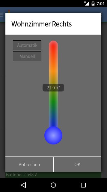
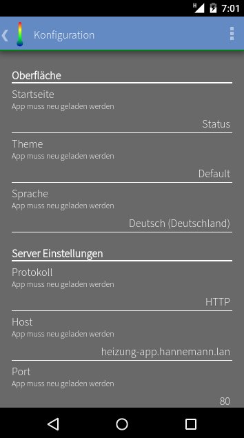
Hello to all,

i wrote a small JavaScript application that can be used as touch
friendly frontend. I hope you find it useful.
I have goth frontends running on the same machine btw. but only one
demon of course.
In the configuration screen just type in the URL of the webapp and
reload the page. Once you added it to youre home screen the webapp will
be launched in fullscreen.

I have a little problem with my master. If the demon is interupted maybe
by power loss its likely to happen that i have to reflash the master. Is
this normal or is there a way to get around this problem?

I followed the piontecs tutorial and everything else is working fine.

Thank you

Hannemann
Jemand schrieb der Stromverbrauch läge im sleepmode bei OpenHR20 mit ca
150 uA etwa 3 mal so hoch wie mit der original Firmware.

Kann mal jemand was zur Akkulaufzeit aus Erfahrung berichten? Wird das
evtl. durch effizientere Motorsteuerung ausgeglichen?
@McFresh: Ich habe eben mal gemessen und komme bei 3V auf 38 µA. Eine
Vergleichsmessung mit der Herstellerfirmware kann ich nicht machen.

Bei mir halten die Batterien gefühlt 1-2 Jahre. Wenn sich der Motor
bewegt, messe ich 20 mA. Ich habe 7 HR20 mit openhr20 im Einsatz, seit
vielen Jahren.
Hi,

I compiled the latest Openhr20 version from github. Everything works
fine but the temperature regulation is very bad. I set it to 20°C about
10 hours ago. Now the vent position is around 50%, temperature is
21,1°C.

When I change settings for the P regulator, like P3_Factor or P_Factor,
I can see a change. Higher values give me better temperature accuracy
but more oscillation due to the high gain.

However, when I change settings for the integrator part (I_Factor,
I_max_credit, I_credit_expiration), I see no response to this values at
all. I tested with minimum and maximum values and nothing changes.
So in my opinion, this is badly broken.


I do not use rfm12 but serial communication and I changed the code as
described here.
https://github.com/OpenHR20/OpenHR20/issues/25
Without this change, the thermostate did not react to serial commands
reliably.

Chris
Hi Chris,

I also have observed the same problem and not found any solution for it.
In my case I even have sometimes more than 2 degreees over the set
temperature and the valve doesn't close further for days.

However rebooting the valve often results better regulation after it got
stuck somehow.
Hello comunity,

i´m new to this project and i have ordered a HR25 for first testing
because of the 32kB flash.

Can you recommend me a cheap JTAG debugger to programm it without
opening the device?

I found one on ebay...

http://www.ebay.de/itm/JTAG-ICE-ATmega-AVR-USB-Emulator-debugger-programmer-/192075040262?hash=item2cb8908606:g:YFQAAOSwYlJW3yue

In the description is no Atmega329 mentioned...
Can any one confirm that i can flash OpenHR20 with this or an similar
JTAG debugger?

If not, will it work for the HR20 (Atmega169)?

Thanks.
It will work, but not with latest Atmel studio based on MS Visual
studio. You don't need to open valve, connector cover is enougth. Note
connector on JTAG and connector on valve have different pinout. You will
need to make adapter.
Thank you very much.


Now i habe some other questions...

I found the OpenHR20 project source on github and on sourceforge.

If i compare the modified date of files on github with that on
sourceforge, i think there could be some differences in the code base.

Is it right that the source on github is the newest or best source to
take?

Are there all commits from sourceforge also on github?

From where downloaded you your sources?
jdobry wrote:> It will work, but not with latest Atmel studio based on MS Visual> studio. You don't need to open valve, connector cover is enougth. Note> connector on JTAG and connector on valve have different pinout. You will> need to make adapter.
My first question was if it will work with the Hr25 (Atmega329) and it
doesn´t work. I can´t programm my HR25 with that fucking JTAGICE Clone.
:-(
Thanks for help to waste money for this unuseful JTAGICE Clone.
Jo N. wrote:> Thank you very much.>>> Now i habe some other questions...>> I found the OpenHR20 project source on github and on sourceforge.>> If i compare the modified date of files on github with that on> sourceforge, i think there could be some differences in the code base.>> Is it right that the source on github is the newest or best source to> take?>> Are there all commits from sourceforge also on github?>> From where downloaded you your sources?
Code from sourceforge was imported to github. AFAIK there were no
commits in sourceforge since then, so github should have everything what
sourceforge has, and more. Which does not mean it must be better ;-).
Regards
Tomas
Jo N. wrote:> jdobry wrote:>> It will work, but not with latest Atmel studio based on MS Visual>> studio. You don't need to open valve, connector cover is enougth. Note>> connector on JTAG and connector on valve have different pinout. You will>> need to make adapter.>> My first question was if it will work with the Hr25 (Atmega329) and it> doesn´t work. I can´t programm my HR25 with that fucking JTAGICE Clone.> :-(>> Thanks for help to waste money for this unuseful JTAGICE Clone.
Although I understand your feelings (also bought few useless clones),
you should have confirmed with the seller, and complain there, not here.
Anyway, maybe if you provide more details than "it doesn't work" then we
might be able to help you. If the adapter really can program the chips
stated in the description (namely Atmega169), I don't see much reason it
should not be able to program also HR25 with Atmega329.
hey guys,

can you please tell me, where I can find the newest sources? In the Git
repo is one project in OpenHR20/tree/master/rfmsrc/OpenHR20 and an other
project in OpenHR20/tree/master/trunk/source. Which one ist the newest
one? I guess the first one, but I can't find an eep file.
With the sources from rfmsrc and the eep from trunk, I get the message
"EEPr" while "booting" the HR20. It stops while checking the EEPROM
layout check.

Can you please give me a short tutorial?

P.S.: I am using an AtmelICE. The HR20 won't get an RFM module, but a
small external PCB with CAN interface.
Hi,
hunt_work_er wrote:> hey guys,>> can you please tell me, where I can find the newest sources? In the Git> repo is one project in OpenHR20/tree/master/rfmsrc/OpenHR20 and an other> project in OpenHR20/tree/master/trunk/source. Which one ist the newest> one?
You found it correctly, the newest should be in the github repository
https://github.com/OpenHR20/OpenHR20. In this repo, the folder rfmsrc is
the latest. The other one is old code without wireless support, but also
without many other changes. We need to clean up the repo, but it has not
been done yet.
> I guess the first one, but I can't find an eep file.> With the sources from rfmsrc and the eep from trunk, I get the message> "EEPr" while "booting" the HR20. It stops while checking the EEPROM> layout check.
I am not sure what you mean by "can't find an eep file". There are no
resulting binaries in the repo. You need to compile the sources first.
Use either make or the compile_hr20.sh script, but modify the parameters
for your configuration first. After compiling, you should be able to
find the binaries (including eep file) in the bin folder.
>> Can you please give me a short tutorial?>> P.S.: I am using an AtmelICE. The HR20 won't get an RFM module, but a> small external PCB with CAN interface.
CAN-bus for thermostats? Sounds interesting, hope you post some more
details later :-).
Tomas
Tomas K. wrote:> You found it correctly, the newest should be in the github repository> https://github.com/OpenHR20/OpenHR20. In this repo, the folder rfmsrc is> the latest. The other one is old code without wireless support, but also> without many other changes. We need to clean up the repo, but it has not> been done yet.
I thought so, but I was confused about the "missing" eep file.
I guessed, i had to flash a standard layout to the EEPROM. I didn't
know, that the compiler creates that file.
I found the eep file in my bin folder. Thank you!
Tomas K. wrote:> CAN-bus for thermostats? Sounds interesting, hope you post some more> details later :-).
Of course, I will write my experiences her, and I guess, I will have
some questions here. ;)
Jonas
I'm thinking of powering the HR20 via its connector. Is this possible?
And if so, is the HR20 3.3 volt tolerant, or does it require a 3.0 volt
input that corresponds to being battery powered?
Hi everybody. Fantastic job. COngrats to developers.

I'm just trying to control a lcd on ATMEGA3290PA on a customized LCD.THe
lCD controller is the same.
 I can't find the meaning of this part of code:

// Look-up table to adress element F for one Position. ( 32 : 10 )
const uint8_t LCD_FieldOffsetTablePrgMem[] PROGMEM =
{
#ifdef THERMOTRONIC
    39,    //!<  Field 0
    35,    //!<  Field 1
#else
    40,    //!<  Field 0
    36,    //!<  Field 1
#endif
    31,    //!<  Field 2
    27     //!<  Field 3
};

// Look-up table to adress a segment inside a field
const uint8_t LCD_SegOffsetTablePrgMem[] PROGMEM =
{
     2,    //  Seg A            AAAA
     3,    //  Seg B           F    B
    27,    //  Seg C           F    B
    25,    //  Seg D            GGGG
    24,    //  Seg E           E    C
     0,    //  Seg F           E    C
     1     //  Seg G            DDDD
};

I really appreciate your help. thank you
Hi,
I just updated to windows10, installed the same toolchain like in
Windows7: WinAVR-20100110, AVRStudio4.18SP3

and did not make any changes to all the sources. As I only did some
small changes to the code years agon I have no idea what the prob. might
be.... please help the novice !!!!

A "rebuild all" brings a fatal error when compiling motor.c.

I guess it has something to do with the .dep directory. It looks like it
cant be created ?? What rights does the directory need or why could the
statement in the makefile fail ?
-include $(shell mkdir dep 2>/dev/null) $(wildcard dep/*)
so I changed the "shell mkdir $(OBJDIR) 2>/dev/null" in the makefile to
"shell mkdir -p $(OBJDIR)" and everything compiles.

2 error 128 messages remain:
if I do the eeprom generation in cmd(no admin) it works:
avr-objcopy -j .eeprom --set-section-flags=.eeprom="alloc,load"
--change-section-lma .eeprom=0 --no-change-warnings -O ihex hr20.elf
hr20.eep  || exit 0
- first probs where beacause of the PATH variable where I had the winavr
tools not at the beginning

- sencond prob is because of an old dll (for W10 I found a dll for
vista)
C:\Program Files\WinAVR20100110\utils\bin\msys-1.0.dll has to be
exchanged
http://www.avrfreaks.net/forum/windows-81-compilation-error?page=all
Hi,
 really interesting project. I would like to buy some HR20s and to hack
them with openHR20. Since the openHR20 project is not recent (first
posts in 2008)and in 2008 HR20 thermostat was different from currently
available, I am just wondering if HW/mcu and display are still the same
or they are different. May someone confirm that openHR is still valid
for current HR20 version, please ?

Thank you.


