Jorg: you are not abble use current wireless code without master. Simply
before master syncronize communication an without master you are not
abble use encryption. But I thing that master is extremely simple and
cheap. If master fail, you are not abble communicate. Current code don't
support communication between two valves (and we have not free flash).

And mainly: "master" is interface between computer and valve wireless
network. How you want to control this network without this interface?

60 measured items on table is used for window open detection. We need to
compare current value and 1 minute old value.
For clarification. CurrentSW can be modified to direct communication
between valves or between remote thermometer to valve. But it still need
"master" for manage network and encryption.

For direct communication without valve you need some caint of "MESH"
network. It is possible if you disable some existing part of SW to save
flash space (for example rs232 com). But it is more complicate than
current communication. It need complete new protocol, complete different
SW layer. And volume of work for RFM12 is sufficient university
dissertation for few peoples (it is not only few lines of code). Another
chance is buy some existing solution (and use another more expensive
wireless modules).
New improvements for 1.00 version are in rev 229:

- configuration for disable/enable ADC measure when motor run
- bug fix for false positive window close detection

Jiri
I have until now the problem with loss of steps (original version 225).
I think that because of the strong spring in the valve the real valve
position shifts a little bit every time the valve is closed.
So I want to correct these "shift values" by a "partial" calibration to
save battery.
 That means: I want to correct the actual valve position only by driving
the valve to the real open position (until the motor stops).

Has somebody a hint for me?

Ronny

PS: I have solved my problem of the recirculation temperature (see Post
on: 2009-03-17 13:38)
at the beginning of CTL_update I save lastProcessValue and sumError.
After calling of pid_Controller I compare the recirculation temperature
with a value stored in eeprom. If the temperature is too high (with
hysteresis) , I close the valve and restore lastProcessValue and
sumError from the saved values. This works for me in a reasonable way...
But the problem of loosing steps exists also with the original software
from the SVN.
@rhb: It is unbelivable for me, that Rev 225 can lost some motor steps.
Absolutly strange.

You don't want to use "partial" calibration, you can use current manual
calibration mode. (Unmount head from valve, manualy close valve, this
position will be saved as "close",  press "C" and mount head to valve
back - keep "C" pressed during this operation) After this calibration
proccess on LCD will not show "Ad 1" etc but "A  1" etc. Motor
recalibration will only touch to "open end" and go back to wanted
position because know "closed position" - saved in EEPROM.

Recalibration is done automaticaly every Sunday on 10:00, you can change
it on main.c

Return to automatic mode is same, butt preess and hold "PROG" button not
"C".

PS: I trust you this problem but I can imagine where is problem, it need
LONG log file from Rev 225 or up.

PSS: how you measure second temperature?

!!!!!!!!!!!!!!!!!!!!!!!!!!!!!!!!!!!!!!!!!!!!!!!!!!!!!
All: we still have problem with window open close detection. After last
change it is better, but it can be false positive or negative again. I
will completly rewrite this part later this week, I have idea how.
!!!!!!!!!!!!!!!!!!!!!!!!!!!!!!!!!!!!!!!!!!!!!!!!!!!!!
Hello Jiri,

my "partial calibration" was only a thought for a workaround to
automatically correct the actual position. I saw the part of the
program, were the full recalibration is done on sunday 10am, but I
wanted to save battery power...
(Thank you for the explanation of the manual calibration, I didn´t
figured out this from the source code - as I said, I´m learning)

My theory is, that the the motor doesn´t lose steps, but because of the
strong spring in the valve the motor is turned back a little bit AFTER
it (and the "photo eye") was switched off and so the actual position is
distorted. So maybe it would help to deactivate the "photo eye" a little
bit later - what do you think?

I started a new log today with original version 229, what do you mean
with LONG time? 1,2 or more days? Or until the valve isn´t closed? Now
this will takes longer because of the warm weather and mainly closed
valve...

Ronny

PS: I measure in my "recirculation temp version" the second temperature
by adding a second thermistor to pin 60 (ADC1) of the ATMEGA and GND (I
don´t need the wireless part) and a resistor between pin 60 and pin 58.
I know, that I decrease the precision of the measurement of the room
temperature with this modification.
@rhb: manual calibration is almost equal to "partial calibration" as you
want. Because range of valve is defined, every calibration in this mode
is simple (go to "open end" and it's done)
@Jiri

here are the long log. At this evening the error happens again. The
valve seems closed (30%), but the heater is warm.
At the beginning (after the calibration) the valve is real closed at 40%
and now the valve is a little bit open at 30%.
The log was made with original version 229. I changed only the
pid-interval to 120 seconds.

Ronny
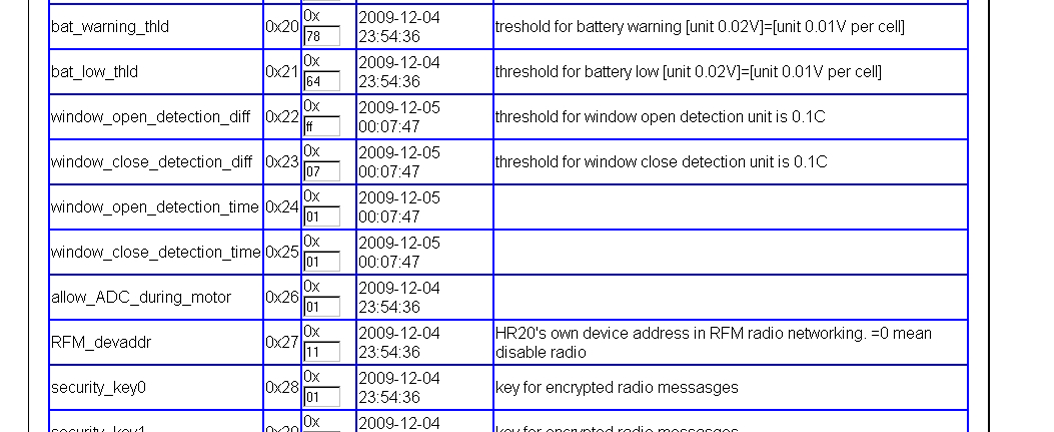
Due to problems with window detection I made completly new window open
detection.

You can test in Rev 232

Configuration options:
1 | /* 22 */ uint8_t window_open_detection_diff; //!< threshold for window open detection unit is 0.1C |
2 | /* 23 */ uint8_t window_close_detection_diff; //!< threshold for window close detection unit is 0.1C |
3 | /* 24 */ uint8_t window_open_detection_time; |
4 | /* 25 */ uint8_t window_close_detection_time; |
How it works:
Program save temperature AVG every 15 seconds. For window open
detection, program compare current actual value with higest value in
selected interval.
Interval is in 15sec unit in window_close_detection_time and detection
threshold value is in window_close_detection_diff.

Window open detection is similar.

Default values is 0,5degC difference on 2 minutes interval. Maybe that
we will need change it.

Jiri

PS to @rhb: thanks for log, I will analyze it today or tommorow.
@rhb: Strange, your log looks perfect. No problem. Where is your
position where valve start opening? (normaly after restart)

On start or end of movement you can found x/X and y/Y chars. This is
signalization where motor stop (logical level). It must be "x" and "y"
every time because we want to stop on low level. When motor move
sometimes during eye is off, sometimes we will see "Y" after x. But it
never happen. (except calibration, but it is due to HW movement limit)
Rev 234 contain paranoid filter for temperature measure (noise
cancelation)
You can try it

Jiri
Hello Jiri,

I think, that I have a log with the error. At this evening the valve was
open at 30% (after calibration it is closed at 40%, so the error is
greater than 10). I set the eeprom valve_max to 90 and then I set the
wanted temperature to 30° (see 06.04.09 20:12:38). The valve wants to
open to 90%, but at nearly 86% the valve blocked and the scale jumps
from 86 to 100% and went then to 90%.

Ronny
@hrb:

- I am surprised, you are realy losing pulses. But it is not on log.

- Jump from 86->100 is correct and I wrote this behavior into SW. In
this situation calculated position is 86%, but valve stop on hard break.
This hard break must be 100% by definition, therefore SW fix current
position to 100% and will continue go to wanted position 90%. This is
partial recalibration initiated by error detection.

Main question is WHY you losing pulses? Have you only one HR20? Can you
try mount this HR20 into another valve?

I have 5x HR20 with my SW byt never see situation like this. Strange.
Problem is that your log looks perfect. Any pulse during motor run can't
be lost becasuse in this condition we can see in log longer time for one
pulse. (second column is time for one pulse) and it looks perfectly
stable without glitches.

Only one idea is, that your valve is too strong and it is abble change
position when motor is stopped. Probably after opening. But in this case
we will see sometimes "X" after "y" but it newer happen in your log.

Strange, strange, strange.

Jiri
Wireless extension: Have somebody "master" hardware already? I would
like ask, before I will change used MCU from ATMEGA16 to ATMEGA32.
Reason is RAM size needed for buffers. If somebody have deprecated
hardware with ATMEGA16, please tell me it !!!NOW!!! (if it is not
possible replace MCU in socket)

Jiri
Hello Jiri,

sorry for the delay, but I tried a second (different) HR20 on the
bathroom valve. But for the warm weather it tooks a little bit longer,
because the valve was closed most of the time. But now I saw the same
situation: I set the max position to 90% - the valve wants to set to 88%
and came to the hard break and jumps to 100 - see the log. I have the
same theory as you: the valve (or the valve spring) is too strong and
can change the position, if the motor is stopped, maybe only a few
seconds after the motor stops. Do you have an idea how this can be
solved?

Ronny
rhb: I have  idea to keep motor eye enabled few secons after motor stop.
But it will be done after few weeks, today I have more urgent tasks.

Jiri
Hi,

the RF-Modul sends at 433 MHz and you need a master to controll the
units?

Maybe the "Betty Remote" can be used to control the single units (or
all).
It has a cc1100 included.

Take a loot at (german only):

http://bettyhacks.com/wiki/index.php/Main_Page

Greets
torrz
I am using 868Mhz modules but it is easy use same modules but for 433.
Problem can be that current SW realy need "master" board. Current
communication protocol is simple and not support some "MESH"
functionlity.
!But! it is open project and your idea with "betty remote" is nice.
Everybody can modify it to this way, but it is lot of work.

Jiri
Hello,

first a big respect to all members in this forum which do a great job to
developing the new firmware.

I was looking for an alternative and found a way to control my HR20 by
my iPhone.

Here a brief description:
I use a master (ATiny2313) and a slave (ATiny2313) which communicate per
radio (RFM12 modules) bidirectional.
The HR20 is connected to the slave and the iPhone communicates via the
master with the HR20. To set the temperature on the HR20 the uC (slave)
is connected parallel to the encoder-pins of the HR20. To display the
set and the current temperature the uC (slave) receives the information
via the HR20-RS232-connector. Then the slave transmits the values to the
master and then to the iPhone.

For a better understanding watch:
http://www.youtube.com/watch?v=w9R1_ee6c6Y

It's only the first experimental step and the development is going on
(pcb layout, control more then one HR20 and so on). But it works.

Many greetings,
puchti
@puchti100:

I thing that control with WEB interface is more comfortable. Please find
snapshots in this thread (example
http://embdev.net/attachment/48705/status.png). It also works on iPhone,
I was test it. It need any PC or embeded linux based router (it is cheap
and power efficient)

But you can create complete another solution, it is your choice and your
time.

Alternate SW you can drive directly via serial line; you don't need
connect wires to encoder (It can work only on one encoder position as
you know)

PS: How you connect "master" (ATiny2313) and iPhone?

Jiri
At my home I've been controling all my audio and video equipments and
also lights per iPhone since one year. I use the iPhone app "CF iViewer"
and the controller of the manufacturer Crestron. It could also be a
PC-application, web interface or a Touchpanel-PC.
In the past I had the wish to integrate the HR20 into "my system".
That's why I looked for a way to do this.

I added a schematic to show how the communication works.

puchti100
sorry again... to fast...
here the correct schematic (copy-and-paste mistake in the HR20-symbol)
@puchti100:
nice, it is solution.

I have few technical notes:
- RFM12 can be connected directly to valve but it will need modification
to your wireless protocol
- be careful if you use battery power, wireles communication is hungry
- alternate SW have public protocol on RS232, you can drive it direcly
without connection to encoder.
good evening everyone,

Can someone please tell me where a user can find generic celebrex online
without a prescription?  I've been referred to
http://www.drugpricegrabber.com but I'm unsure how to determine whether
their site is trustworthy.
Hi,

I have connected the rondostat to avrisp, via JTAG cable.

I am trying to use AVR Studio.

Which Amtel chip does the rondostat have? How can I check?

thanks
Chip is ATmega169P. Programmer can read and check chip signature without
programming.
I'm about to buy some HR20s to join this very interesting HR20
development. However, I got a few questions.

1) there is HR20E and HR20N. The HR20N seems cheaper. What's the
difference? Are they both ok for OpenHR20?

2) are there different versions of HR20? are they all ok for OpenHR20?
(like the Linksys WRT54G with a lot hardware difference for different
versions)

3) I plan to add a Zigbee tranceiver. Has anyone already done this? The
PCB size is about 20mm x 30mm x 3mm. Is there such room inside the
valve?

Many thanks
David
Hi,

This thread seems a bit quiet recently, maybe, because the weather is
still warm and there is not much need for heating.

Anyway, after a few days research, I plan to do the following based on
the current code/design;

- Add a different wireless transceiver (client). It is going to be an
A7105 based transceiver. The reason for different transceiver is that it
works at 2.4G and hence smaller antenna and faster data rate. Also, it
takes 3 wire SPI instead of 4. So I can use the PE2 (Sorry about the PIR
idea. But I think it can go with another A7105 transceiver.), RXD and
TXD. They are a lot easier to solder.

- Build a, maybe too ambitious, server. The server will have,
 1. Graphic LCD 128x64;
 2. A keypad and dial;
 3. AVR MCU; (can be ARM but I do not want to involve another different
tool chain)
 4. Two A7105 tranceivers: one for normal using; one for alternative
channel when there is jam;
 5. One Blutooth module with the RS232 profile, which can be used to
connect a PC;
 6. It's going to be powered from main through an adaptor.

- Build a boilder switch (another client). This switch has an A7105
transceiver and a simple AVR. It is going to be powered by batteries
only.

Each client will have to register with the server. The server Assign a
key and a device ID to the client. The A7105 can help to filter the
device ID. However, the communication packet will be encrypted with the
key.

Periodically the client will connect to the server to post its own
status and check out command. The detail of the protocol has not been
decided yet.

If a client, after certain retries, can not connect to the server, it
will switch to the alternative channel.

Time for bed now. I'll post more later.

David
@davidfat:

2.4GHz is not good idea for this. Many building have steel/concrete
parts and this building have BIG problem with wifi from room to room
communication. It is same wavelength. Except this, in city center I can
found over 50 wifi networks and it make communication near to
impossible, noise is too big.
Data speed is not critical, battery life is bigger broblem. Antena
length is not problem on 868MHz (RFM12 modules, antena fits inside valve
I will post photos), and wavelength is better for comunication throw
walls.

For "server" I has another goal. For me is not critical direct
connection to computer, but connection to internet. It can be maintained
remotely. Therefore I was use minimal AVR based protocol translator and
mips/linux based small router.

But stand alone server is significat for many others people, I hope that
your ideas have many potential users (probably include you)

@Others:
I have some small changes  in code on todo list, It come from real
usage.

- battery warning or error will be one way. When battery is on end of
life and not on drain it measure too opimistic values.

- less communication. Enable slave receivers twice every minute for few
miliseconds is too expensive (battery life). Current plan: communicate
on changes or every 2(4) minutes or twice every minute if user activity
is detected.

- improvements on WWW interface.
@jdobry

868MHz has better path loss. However, given similar size, its antenna
may be not as efficient as a 2.4GHz one. I'm interested to see your
antenna inside the HR20.

Higher throughput for a network is still good, at least, a) it takes
less time to transmit, hence saving power; b) the channel is less used,
so better latency.

I also feel the bandwidth can be used in 868MHz is actually just 1MHz
(868MHz~869MHz). When there is interference, there is less space to
maneuver. Although 2.4G band is quite busy, the protocols there can
normally use FHSS or DSSS to make robust link.

One more thing worries me about the RFM12 is that, according to its
datasheet, its lowest working voltage is 2.2V. If the HR20 is powered by
NiMh batteries, the voltage may be blow that when there is still half
capacity left. Have you got chance to test an RFM12 at something like
2.0V?

The server sounds better to be made with a PoE interface, and it'll need
an ARM.

Re the transceiver power consuming. Suppose a short heart-beat packet is
sent from a client to the server every 10 second. The heart-beat packet
consists of 4 byte preamble, 4 byte server ID, 4 byte client ID and 2
byte CRC. The packet is FEC encoded, hence take 7/4 of the raw length.
So it has (4 + 4 + 4 + 2)  8  7/4 = 196bits. Given 250kbps, it takes
0.784ms. The client will also try to receive a wake-up packet from the
server, which is of same size. So roughly the whole procedure will take
about 2ms. A7105 has RX current 16mA and TX 19mA. One heart-beat costs
about 35mAmS. In one day there are 24*3600/10 = 8640 such communication,
and it costs 0.084mAh. A good battery gives ideally 2000mAh, which means
65 years. Let me know if this is possible or I did my calculation wrong.
I don't see RFM12 consumes more power. Why you can't do it twice every
minute?

When there is need to post server any status from the client, the client
will wake up by itself. Or if the server wants to talk to the client, it
sends a wake-up right after the client heart-beat. The client
transceiver goes to sleep after certain time no RF activity.
@davidfat:
You calculation about battery life is bad. Problem is not energy for
send data (it is small). Problem is here:
- internal PLL loop for frequency syntetizer need some time to
stabilization, it is more time than for TX data.
- current for RX is near to same as for TX, and because timing can't be
perfect, you need enable it few ms before packet.
- "heart-beat" packet must be also encrypted. Reason is potential
synchronization poisoning from attacker.

PS: Where is datasheet for A7105?

Jiri
@jiri
At 2.4G the PLL seems to lock faster. According to the datasheet I think
the extra overhead would be about 200us. However, without testing, I
can't confirm. I would say bad programming if you can only get real-time
response in a few ms. It is quite possible to get sub-100us timing
accuracy, or even better with a simple device like AVR, for example, the
heart-beat proceding can totally be done in the ISP. You don't need to
identify someone before he/she can knock at your door. You just need to
do the checking/encryption before letting him/her in.

The datasheet is here
http://bbs.ednchina.com/Upload/Blog/2009/3/7/6e103b04-069a-4099-abbd-12a425b6990a.pdf
@david:

- Oscilator start-up overhead is 2mS (page 7 of datasheet)

- timing precision cant be better than 3.9mS Reason is 32768Hz x-tal and
prescaler /128 . If you will use smaller prescaler you will increase
volume of CPU wake-ups and it is not good for bateries. Use internal RC
oscilator for this situations is also possible, but battery hungry.
@jdobry

- Even if it's 2ms, it only lowers the battery life for transceiver from
65years to 32.5 years. Also, the standby state consumes much less power
than TX/RX state. The 2ms is the time from sleep to standby. Interestly,
although in the table it gives 2ms, in the diagram on page 38, it is
0.9ms (from sleep to PLL).

- Absolute timing does not matter. When sending the heart-beat, MCU a)
wakes up at certain time, b) disables all other request (for better
determinstic timing), c) changes to 1MHz or so, d) wakes up the
tranceiver, e) goes to idle/sleep(if possible) for 2ms, f) sets up the
PLL, and idle for 80us, g) triggers the heart-beat sending, (the
heart-beat packet can be stored inside the transceiver, so everytime you
only need to trigger it), h) sleep/idle 0.7ms, i) keeps checking until
TX finish, j) sets transceiver to RX, k) sleep/idle 1ms, l) checks if
any wake up packet received, m) transceiver goes to sleep. I think
that's pretty much the whole heart-beat procedure.
Hi

Build environment?
Just found this project and is very eager to try to build the software
and hack my HR20 thermostats. I have more than 10 in my house.

Unfortunately I'm not very good at German so I have some troubles
understanding the "Heizungssteuerung mit Honeywell HR20" page. Is it
correct that I need WinAVR or "AVR Studio 4" to compile and they are
both Windows only tools?

I am not wery experienced with Windows and have no license so I really
would prefer a Linux based development platform. From the discussion
above I see that some of you prefer *nix as well. Is it possible to
build and download the project on a linux platform?
@Mr_Manor:

AVR Studio is needed only for debugging, not for compilation.
For compilation WinAVR-20071221 compiler is recomended. Reason is that
newest GCC produce significantly longer code and it can be too big into
flash. But it depend to configuration. Linux distributions usualy
contain AVR GCC and avr-libc. You must try it.

Or you can use precompiled HEX from repository.

For programming use avrdude tool.

Jiri
PS: from where are you?
@jdobry

ok, thanks for your answer. I have installed VirtualBox and XP within so
I hope that will enable me to compile. I'm very interested in the
Wireless branch - several years ago I was into hardware so I think I am
able the build the radio into the device. Is the project state as
described on on the wiki page up to date?

I will most likely return with more questions when/if I get a build
environment working ;-)

I'm from Ugerløse,Denmark.
@Mr_Manor:
Information in wiki is not 100% up to date. But information in SVN is
up2date. SVN contain schematics and photos for wireless modification.
And if you want know communication protocols you must read source files,
it contain human readable documentation. Low level wireles layer have
documentation file in SVN (PDF and OpenOffice file).

Many greetings from Czech rep. Jiri

PS: I also use Linux at home, 100% in desktop and 80% in laptop.
Remaining 20% of laptop time is WinVista because linux have not comfort
tools for AVR debug :-(
Hi,
Is it possible to switch between full-stroke/default-stroke mode on a
"not-hacked" HR20? (I don't have the necessary hardware).

BR, Thomas Fogh
@Thomas Fogh: It is for ORIGINAL SW:

FULL stroke mode: unmount valve, press and hold "C" button, mount valve
and you will see "FULL" on LCD

DEFault stroke mode: unmount valve, press and hold "PROG" button, mount
valve and you will see "DEF" on LCD
@jdobry:
Thanks! But what's the "C" button?
I have the "auto/man", "prog" and the day/night temperatur buttons.
BR, Thomas Fogh
I mean day/night middle button. Because moon looks like "C" :-)
Any news on the development?

I'm going to move during the turn of the year and then would like to use
some RFM-enhanced HR20.
At the moment, I've only got two with the stock firmware, because I
couldn't get my USBprog JTAG to work yet :(
But I would buy a "real" JTAG adapter if I need to :)
@Marco G." RFM12 sotware simply works on my home. I have plan to some
improvemnts, but nothing critical.
Hi jdobry,

I guess you mean the firmware compiled from the repo/rfmsrc/OpenHR20
directory?

And you are using the "internal_RFM12" hardware modification? Is it
difficult to use the external one?

And what's your master? A HR20 with a special firmware or an extra piece
of hardware?

Please excuse my pile of questions, if there is any documentation please
point me to it :)

I hope I'll be able to improve the documentation soon :)
My answer from yesterday evening didn't make it into the forum :(

By reading through the thread I found out that the master is an
ATmega+RFM12, connected to an OpenWRT router.
@Marco G.
Diferrences between internal and externel RFM12
- with external RFM 12 you can't use ICE debugger
- external module can be easily damaged or accidenataly disconnected. It
is significant if you have childens.
- internal version need expert skill for soldering, chiset pins is
extremely small.

And you are right. "Master" is RFM12 + Atmega connected to OpenWRT based
router (I was test it with Asus GL500-deluxe and Buffallo WHR-G54S) It
provide web interface for valves ( Yes, it can be used by iPhone :-) or
any bother browser )
Hmm, you're right about the risks of an external module, but I thought
it could be easier to connect a cable to the 10-pin connector but put
the module inside.

Can both - internal and external - be used? There are preprocessor
defines, but also a warning message in
\rfmsrc\doc\external_RFM12\README.txt.
Warning in  \rfmsrc\doc\external_RFM12\README.txt is little bit
obsolete.
You can not use it with birary files in SVN, it need recompilation where
you change hardware type.
jdobry, do you already have a PCB for master hardware?

Or does anyone else have a layout?

If not, I would design one and order some PCBs...
No I don't have PCB. Just prototype on universal PCB and wires. If you
will have it, please send me one.
Ok, that will be my task for the weekend :)

Maybe we should start a new thread for designing the PCB:
http://embdev.net/topic/158895

But I'm unsure about the connection to a router. Does yours have a
serial interface?
@Marco G.:
My router have serial interface inside. (3V3 logic levels)
Hello All,

I am new to this forum so thought to be first introduce myself, i from
Gray Mountain and interested in Internet Surfing, Forum Posting and
Listening Music specially the old clasics

Even i thought forum posting is one of the best way to enhance knowledge
as well grab new things, that is the reason me joined this forum, i
found this forum very informative and valuable, it is really great to be
a part of this forum.

Thanks & Keep Sharing!
Hello,

I use my HR20 (currently one) with an external 433MHz RFM12 module from
Pollin. I modified the initialization of the RFM. I set the Band to
433MHz  and the capacitor to 12.5pF. The frequency is 434MHz and the
range limit is set to +3-4 for 433MHz band ,respective to the
programming guide. My master is an ATMEGA32 on an prototype PCB  powered
via USB. Now my problem: I start the master and the daemon and the first
5minutes all work well .Then I receive only errors for hours, sometimes
it work for a few packet and then the same problem. If I restart the
master , the first minutes it work well. What´s wrong ? Have somebody an
helpful hint ? Maybe is there an wrong initialization value for 433MHz.

Thanks in advance!
Ronny
@Ronny Kunze:
Can you send me any log? One of possible problems is time
synchronization. Master broadcast real time and slaves enable receiver
for synchronization packet. Real time is one of parameter to encrypt
packet and if master have another time than slaves, encryption not work
and it can't decrypt packages.

Master clock is not from XTAL but from RFM12 clock output (10MHz). Maybe
that you change it on init sequence.

What happen when sync is lost?
- Master normaly send SYNC packet on 00 and 30 second in every minute
- Slave show "E4" error
1) Slave try enable receiver for 4 minutes till receive SYNC
2) When SYNC is not found,  receiver will be disabled for 40minutes
(save batteries) and after go to step 1)


Jiri
Hello Jiri,

did you mean the Debug log in the database or the log from the daemon ?
The Masterclock is from RFM and it is 10MHz , i have veryfied it whit an
oscilloscope. THe Slave doesn't show E4 and if i change the time on my
HR it will set back automaticly to the time of the master.

Here a short dump :
2009-12-08 12:38:07      @07.48 ERR04df 24 06 3f e4 44 43 b5 0f 87 1d...
2009-12-08 12:37:07      @07.49 ERR04de 24 06 18 e5 38 f7 08 55 b7 b0...
2009-12-08 12:37:01      ?
2009-12-08 12:36:07      @07.50 ERR04dd 24 06 63 38 37 91 0e 06 60 c5...
2009-12-08 12:35:07      @07.49 ERR04dc 1a 06 9f 7b 8a e8 dc 5e b7 c3...
2009-12-08 12:34:07      @07.49 ERR04db 1a 06 51 80 12 51 cf e8 0a c6...
2009-12-08 12:33:07      @07.49 ERR04da 1a 06 7c d0 06 01 67 d6 97 c3...
2009-12-08 12:32:07      @07.48 ERR04d9 1a 06 ee 43 5d 7e cf f9 22 47...
2009-12-08 12:31:07      @07.49 ERR04d8 10 06 f1 b3 10 9a 73 b1 5a ca...
2009-12-08 12:30:07      @07.47 ERR04d7 10 06 38 65 40 95 3d 99 6e 17...
2009-12-08 12:30:01      ?
2009-12-08 12:29:07      @07.48 ERR04d6 10 06 80 aa d5 32 4d b3 48 ec...
2009-12-08 12:28:30      @30.11 ERR04d5 8c 70 ec 16 26 33 de ad 7c 2e...
2009-12-08 12:28:07      @07.48 ERR04d4 10 06 9e 84 0f 48 e1 6f 7b 6b...
2009-12-08 12:27:07      @07.45 ERR04d3 06 06 e7 f5 fd 16
2009-12-08 12:27:01      1)?
2009-12-08 12:26:01      @58.57 ERR04d2 3f b7 3d 45 91 08 04 55 ac 3c...
2009-12-08 12:25:07 <06> -D m32 s03 - V46 I1884 S1900 B2941 E00
2009-12-08 12:25:07 <06> -D m27 s49 - V45 I1885 S1900 B2940 E00
2009-12-08 12:25:07 <06> -D m23 s39 - V45 I1890 S1900 B2947 E00
2009-12-08 12:25:07 <06> -D m19 s28 - V45 I1890 S1900 B2956 E00
2009-12-08 12:25:07 <06> -D m15 s16 - V45 I1890 S1900 B2953 E00
2009-12-08 12:25:07 <06> -D m11 s06 - V45 I1890 S1900 B2946 E00
2009-12-08 12:25:07 <06> -D m06 s55 - V44 I1897 S1900 B2956 E00
2009-12-08 12:25:07 <06> (06){
2009-12-08 12:25:07      }
2009-12-08 12:25:07      @06.13 PKT04d1
2009-12-08 12:24:07      @07.54 ERR04d0 4c 06 86 c7 c2 14 5c b1 10 b0...
2009-12-08 12:23:07      @07.54 ERR04cf 4c 06 5e bf 45 ae c3 c4 b3 11...
2009-12-08 12:23:01      )?
2009-12-08 12:22:07      @07.53 ERR04ce 4c 06 50 de 31 23 24 86 62 0a...
2009-12-08 12:21:07      @07.54 ERR04cd 4c 06 b9 c1 c0 35 56 74 1b c9...
2009-12-08 12:20:07      @07.54 ERR04cc 4c 06 25 9d bf 22 22 ec fd 52...
2009-12-08 12:19:07      @07.54 ERR04cb 4c 06 9d 3e 1f 97 a3 ec c6 d8...
2009-12-08 12:18:10      @09.95 ERR04ca 4c 06 e0 24 03 12 bb 1f 4a bb...
2009-12-08 12:17:07      @07.54 ERR04c9 4c 06 f7 2d 46 33 e2 67 88 d2...
2009-12-08 12:16:07      @07.53 ERR04c8 4c 06 23 54 02 7b ac 24 e9 80...
2009-12-08 12:15:07      @07.55 ERR04c7 4c 06 9b 1e 10 aa ad 18 d2 aa...
2009-12-08 12:14:07      @07.53 ERR04c6 4c 06 38 b1 45 f5 7d a7 87 b9...
2009-12-08 12:13:07      @07.54 ERR04c5 4c 06 2d a6 5d 22 18 c0 7d 07...
2009-12-08 12:12:07      @07.54 ERR04c4 4c 06 d1 e3 50 72 91 a3 f1 97...
2009-12-08 12:11:07      @07.54 ERR04c3 4c 06 11 38 b5 a1 64 fd 0c 98...
2009-12-08 12:10:07      @07.54 ERR04c2 4c 06 96 e8 a5 af 38 3e f1 a6...

Ronny
How often is the Time of the Master synced whit the PC ?

The timedrift on my ALIX2 is very strong , so i update the Time from a
NTP server every 10 minutes. Could this problem influence the decryption
?

Ronny
It looks like lost SYNC.
"Master" ask daemon on computer for time every minute and daemon tell
time in 1/100 precision. Do you use Windows or Linux? I am not sure if
Win&PHP combination can use this precision. Part of encryption key is
created from time. Therefore key in 0.99 second is not same as 0.01
second. If daemon is not abble te tell time in this presisoon, time in
master must float over +- 1 sec adn it is not abble to comunicate. It is
just idea.

PS: I use NTP for real time in router where runs daemon. But absolute
value is not significant.
@Ronny Kunze:

I read the log ant it is definitively lost of SYNC. See too log and
follow my sentences:

- Log is in reverse order
- You have slave with address 6. This means that timeslot for
communication is from 6.00 to 6.99 second


2009-12-08 12:25:07 @06.13 PKT04d1
- Is correct packet received in 6.13

2009-12-08 12:24:07 @07.54 ERR04d0 4c 06 86 c7 c2 14 5c b1 10 b0...
- Correct packet from 06 (see to second byte) but received too late on
7.54
- Packet like this can't be accepted, because encryption key is expired
and normaly this is possible only on "replay attack"
- This means that master receive from daemon wrong time. Maybe without
correct 1/100 second and "jumping" around correct time.

If you want to have better verbose log (include time sending
daemon->master) you can start daemon without redirect to /dev/null
because it generate verbose log compare to log stored in database
(database engine is too slow for it on embeded routers)

I apologise to code qality on current "daemon". This peace of code was
hang together as proof of concept when I need to debug code in master
and slave. I was plan to rewrite it completely, but it not happen (have
not time and urgent motivation). But it works.
Hello Jiri,

I think i found the problem. I tried following on my server :
1 | voyage:~# ntpdate ptbtime3.ptb.de;sleep 60;ntpdate ptbtime3.ptb.de |
2 | 9 Dec 09:29:38 ntpdate[30871]: step time server 192.53.103.103 offset -0.749543 sec |
3 | 9 Dec 09:30:37 ntpdate[31034]: step time server 192.53.103.103 offset -1.480186 sec |
Lo and behold! The drift whitin 1 minute is around 1,5 seconds.
Then i tried to update the clock every minute , it looks better. At
least i tried to update via ntp every 10 seconds and every packet is OK
...

It seems i should fix the problem on my Server ...

Regards,

Ronny
Can you use ntpd (daemon) and not ntpclient? It is abble to compensate
drift.
Hello,

is there a how-to-file or wiki for beginners/dummies?

Peter
Hi Peter,

I've started one, but haven't got further than flashing yet :(
Hello Jiri,

Yes I use ntpd , but it was not precise enough. Now i found a other
solution. I have modified the handling of the time update at the
master.The request is send every minute , but it ignore the the answer
if onsync greather than 0xe1. This should be a time of 1 hour.

I found a other problem in the daemon. The serial connection will only
work if the system set the right baudrate. I add a
exec('stty -F /dev/ttyUSB0 38400 '); to the daemon. Now it is anytime
the right baudrate.

Ronny
Hello,

i have just converted my 2. Hr20 to the Open Hr20 with an RFM12 module.
when i measure the current, the Hr20 takes around 1 mA. This current
consumption seems a little bit high.

Ludger
Ludger: I know that we have some problem with wireless and power. Normal
cheap alcaline batteries is empty after 2-3 months. I will try fix it on
xmas vacation.
Till now I has feeling, that nobody except me use use wireles in HR20,
but it slowly changes in last two months. :-)
Hi Jiri,
now that we are back in heating period again :-(, I have changed two of
my HR20 running older versions of the OpenHR20 firmware (still without
wireless) to the newest (?) version 234.
Experience so far: both failed miserably, showing 'Open' for hours and
both rooms cold this morning and again this afternoon (my wife is not
amused).

Best thing for me at the moment would be to disable the window open
detection completely (any hint how to do that easily by changing
parameters ?).

Regarding your last post about wireless. I think one of the reasons why
this is not used by so many people is:
- the lack of an easily available master unit
- the way you are using it (with a router as master control, maybe too
complicated for most of us ???)

What I would love to do is have the individual units run on their own
with their own sets of parameters and monitor these units via wireless
with a master unit most of the time. Only in some special situations I
want to control the units remotely, e.g.:
- if the circulation pump is not running (at night)
- if i leave the house for a weekend holiday
- .....

BR,
Jörg.
Hi Jörg,

i have had the same Problem with my HR20. Here are my settings to
disable the window open detection.
Hello Jiri,

I think the problem with the current consumption, ist the crystal
oscilator of the RFM module, it's always on. I can measure the output
frequency of 10Mhz. You can switch off the the oscilator output to save
some energy.


Ludger
Hi Ludger,
thanks a lot for this info regarding window open detection. I will try
that immediately.

BR,
Jörg.
Why don´t you switch off the RFM completely with a little transistor, if
it has nothing to do? I would implement short time slots in the
protocol, where the module is active and waiting for incoming data or
transmitting.
Opps, RFM oscillator must be enabled only in master (it is used as clock
for ATMEGA) but not in valves. I will fix it early (I hope today). We
don't need switch off RFM by transistor, it can be switched off by
command, I don't know where is problem for now, but I will find it.

Window: In current SW is this third version for window detection, and I
have similar problem. Do you have anybody idea to improve window
detection algorithm? For next version I will prepare window open timeout
( from 1-255 minutes ) When HR20 clear window open flag automatically.
Current detection is too sensitive, and today during change from 21 ->
17 degree detect window open in 3 rooms. Temperature decreasing too fast
(outside temperature was -16)

Master: It can be connected directly to PC, not to router. It is less
complicated, but you can not set valves remotely. Remote control is
fundamental feature for me, sorry. This SW can be installed on PC but is
is not optimal. If you have not permanently enabled PC, you will not
have logging.

GPL: it is GPL SW, this mean that everybody can modify it by own felling
what is better :-)
>We don't need switch off RFM by transistor, it can be switched off by
>command,

Sure, but how big is the quiescent current consumption in power down
mode? Is it noticeable, compared to the Mega169, or not?
@ TravelRec

Hi,

i have running to RFM12 + SHT75 + Tiny45 for almost a year now. And the
batteries ( 2 Alkaline AA ) are the first. The current consumption quit
low


Ludger
Ahh, okay. In my tests the Mega169P needs around 25µA during sleep with
LCD active and cyclic main calls 4 times a second. If the RFM takes more
than 10µA all the time, then the battery life will decrease
dramatically.
Jiri,
I think the idea with a programmable timeout after window open detection
is the best , because I can not imagine how it COULD work automatically
regarding the huge variety of circumstances (we have the same -15°C here
at the moment as you and the room temperature falls extremely fast and
never recovers. Temperature regulation is also not nearly perfect.
Because of the low temperatures outside and high heating water
temperature I see extreme overshoot in very small rooms with
comparatively big radiators whereas in other rooms temperature increases
very slowly with valves full open).

One other (maybe optional) possibility if the HR20 is located near to
the window/door would be to use one of the cheap reed contacts for
burglar alarm and cable this directly to the HR20 interface connector.

And, yes, I know that everyone is allowed to change the sources :-), but
there is simply not enough time for me to do that.

BR,
Jörg.
@ Jiri,

i know about the GPL, but i have some problems to compile the source
file correctly for a running HEX file. The compiler has the right
version and use the makefile for compiling. Do you use AVR studio for
building the HEX ?
I got always a lot of compiler warnings.

regards
Ludger
Jiri, Ludger,
for me the .aps file in the wireless directory works perfectly, whereas
the one in the trunk directory does not. Calling make from command line
works (although I am not the command line guy, started with that 35
years ago and am happy that we have fully integrated graphical
development environments now!).

If the .aps is not maintained any more, than it should perhaps be
deleted.

BR,
Jörg.

PS: Ludger, changing the parameters for wod worked for me, warm bathroom
this morning, happy wife :-),.... thanks again.
Jiri,
has anything been changed on the serial routines? These worked ok in
V2.03 which I used in my HR20 before changing to V2.34.
Now I get a number of rubbish symbols when the HR20 answers to a command
before the correct answer (like yyyyyD: d4...) and nearly only rubbish
(yyyyyyyyyyyyyyyyyyyyyy......) when the units send their message every 4
minutes. I have no clue at the moment what's going wrong.

BR,
Jörg.
@Jörg Becker: It is debug messages when I was try find reason of motor
position offset on some situations. You can disable it by set
DEBUG_PRINT_MOTOR to 0
But main trun at this moment have not maintainer, therefore I am
recomend use rfmsrc trunk na compile it like "make RFM=-DRFM=0" or
disable RFM extension on config.h

ALL: new rev 253 in SVN have this changes:
- window detection have timeout, default value is 90 minutes. After this
time window open flag will be cleared in eny situation.
- This version is possible compile without RFM extension
- I was add one more "watch" to count all motor pulses (diagnostic)
- this version is NOT fully tested, I am just commit wirking version
because I need to continue find problem with current on sleep state
(only for RFM)
Jiri,
thank you for the info. I got it to compile and work.

BR,
Jörg.
Current from batteries on RFM12 is fixed in revision 254. Actual current
is arround  40uA on standby.

Oscilator was enabled because I forget disable RFM12 CLK output. Oposite
to official documentation it enable oscilator.
WARNING: Be sure that "OCDEN" programming flag is disabled after
programming. It is usualy enabled by debbuger, and it take over 1mA from
batteries.
Do you have anybody this alternative to HR20?
http://media.conrad.de/m/6000_6999/6100/6160/6161/616100_LB_00_FB.EPS.jpg

I would like to know what HW is used inside. (Microcontroller, radio
module). If it is AVR based, it can be used on this project.
@ Jiri,

tell me more about the motor offset problem, maybe i can help.....


Ludger
Merry christmas together,
I'm still busy on writing my own firmware for the HR20E - it's still
done in Assembler. Nearly all functions, also the wireless communication
are intergrated and working fine. Now I want to integrate the
,window-open' functionality too. But how can I realize the algorithm to
do that. How many (centi-)degrees diffrence by what time detects the
,window-open'- state ?

Sorry for my freshman english...
Marcus
Marcus,
the original algorithm is written in the HR20 Datasheet:

"Bei Temperatur-Änderung von 1,5°C/3Min. schließt das Ventil u.
öffnet wieder bei Temperaturanstieg o. spätestens nach. 45 Min."

-> slope must be at least 1,5°C in 3 minutes to detect a window change,
and a 45 minutes timeout is used.

The datasheet can be found at Reichelt.de:
http://www.reichelt.de/?;ACTION=6;LA=3;ARTICLE=78795;GROUPID=4382;GROUP=X3512;SID=25xmeW-6wQARkAAB5lc1c9d7ce1750ec4debf08b1b6f0f631ba64
it can also be found there:
http://www.rondostat.net/fileadmin/content/02_pdf/honeywell_db_HR20E_210x297_FINAL.pdf
:)
@ Marco,

thank you for your support, I've read the consumer documentation. I
think the threshold of 1,5°C is in many situations too much - it takes
too long till the software detects the open (only tilted?) window. There
should be an integrated dynamic component, consisting of the
in-,decreasing PID-Value's tendency and the sign of the D-Part (last
measured temperature higher/lower than the current value)?
Last night I advanced my PID by this extension and to time it's looking
good.

Marcus
Well, I've used the original HR20 firmware last year, and it did
recognize my open balcony door almost immediately. Of course I opened it
completely and did not tilt it.

Marco
An open balcony door causes a big and fast heat loss - the temperature
decreases rapidly, so it's easy to detect this. But a slow loss - about
a few centigrades/PID-cyle cannot be recognized by this way. I think the
valve constantly opens until the limit (or setpoint) is reached, or am I
wrong?

Marcus
Yes you're right, that's a big heat loss. But isn't opening a window
completely the "better" way to exchange the air in a room?

I don't know anything about the original nor the OpenHR20 algorithm :(
Yes, indeed. But not every window can be completely opened - like mine
in the attic. I also consider this function as a kind of protection for
forgetful people who forget to close their doors/windows - it's not
really required for a few minutes air exchange.

Marcus

PS:Do you use OpenHR20 on your valve(s)?
Jiri reported about some very cold days when his /window open/-detection
falsely recognized an open window. Maybe a reed contact connected to a
GPIO would be more suitable?

I'm not using OpenHR20 yet, I'll be moving at the end of February and
then start with OpenHR20.
I'm seeking for a solution, without any external switches cabled to the
valve. The evaluation of wireless informations, for example a window
open detection or distant temperature values is already is already
supported  by my software but not used. Perhaps in the (distant)
future...

Marcus
Here's my master board. Any suggestions? Anyone who is interested in a
PCB when I order some?

http://embdev.net/topic/158895#1533392
RFM12 modification users:

!!!!!!!!!!!!!!!!!!!!!!!!!!!!!!!!!!!!!!!!!!!!!!!!!
Please update to version E0.07 (SVN revision 261)
!!!!!!!!!!!!!!!!!!!!!!!!!!!!!!!!!!!!!!!!!!!!!!!!!

It contain bug in time setting and program temperature change can be
lost.

Old version without RFM12 modification and compilation with RFM12
disabled is not touched.
Issue still not completly fixed, it have one more layer on AVR rtc
timmer synchronization. It will be fixed tomorow, it's too late.
Hello,

now my patch for the second LED for the master . It is adapted to the
Version from Marco G.
RFM12 modification users:

!!!!!!!!!!!!!!!!!!!!!!!!!!!!!!!!!!!!!!!!!!!!!!!!!
Please update to version E0.07 (SVN revision 263)
!!!!!!!!!!!!!!!!!!!!!!!!!!!!!!!!!!!!!!!!!!!!!!!!!

It contain bug in time setting and program temperature change can be
lost.

Problem was in timmer2 async opertaions.

Main trunk is also touched, but it can't lost point in program. In this
case update is not critical.
Hello,

I recently changed my old HR20 (which work with a nec micro controller)
by new ones (HR20 not HR20E). I tried to connect one of those to the
computer but get constantly the error :
---------------------------
AVR Dragon
---------------------------
Unable to find supply voltage on target.
Please verify that the AVR Dragon is correctly
attached to the target, and that target power has been
switched on. Click OK to retry.
---------------------------
OK   Cancel
---------------------------

The Board seems to detect 2.7V, but as soon as I try to read something I
get this error and the voltage drops to 0.2V which seems to be the
default voltage when nothing is connected.
I don't know if I'm doing something wrong. Could someone help me please?
Hello Manu,

This sounds like a wrong connection of your HR20E to the AVR-Drangon.
May be the voltage measured by the Dragon is one of an IO Port.
I use also a Dragon and it work fine.

Ronny

My adapter :
HR20        DRAGON
1   RESET      6   nreset
2   PE2        -
3   TMS        5   TMS
4   TCK        1   TCK
5   TDO        3   TDO
6   TXD        -
7   RXD        -
8   TDI        9   TDI
9   BAT        4   VREF
10  GND        2   GND
Yes it works! Thanks a lot for the info. I guess I tried to go too fast
without first reading all the docs.
@jdobry (2009-12-21 10:51):

I have one of those devices (article number 616100 - 62 @ Conrad's). The
board looks a little like the one mentioned here:
Beitrag "Untersuchung Heizungsthermostat Lifetec MD12460" (German) except the second
chip IS mounted (under an "Epoxy Glob Top", like the first) an it is a
lot better processed ;-).

Sorry, a few low-quality pictures from my mobile phone is the most I
could offer you (I'm an absolute doofus in terms of "analyzing" such
boards. could help with Java/PHP or a small virtual host, though :-) )
@MajorTom: Thanks, but it NOT look like compatible with OpenHR20. But I
hope that I miss and inside Blob is ATMEGA.
Hello Forum,

i am new to the Forum, but have some experience with embedded devices,
and have "steckbrett-fun" with  the Atmel uC for some time.

We have several Thermotronic "Sparmatic Basic" Thermostats in use and i
wanted to hack around with them. I found the OpenHR20 project and must
say you have done fantastic work. Also the simulation of the Display is
very cool.

I tried OpenHR20 with one of them. (downloaded the code from svn, built
it with the define THERMOTRONIC, chiperased, flashed flash eeprom and
fuses (fuse values as shown here
http://www.mikrocontroller.net/articles/Heizungssteuerung_mit_Honeywell_HR20#Fuses
)

It boots, runs the motor forward and back, but shows an "E3"
All menus operate properly, i can set the time and so on.

From the code i understood that E3 means the motor doesnt run properly.
The Reflexcoupler works (measured a signal at PE1)

I both tried with batteries and external power supply, because i read
something about that in the Forum - makes no difference.

Before digging deeper into the code i'd like to ask you.

Do you have any clues ? Perhaps Confiuration values to adapt to make the
software more tolerant ?

Is there anyone running OpenHR20 on a real thermotronic device ?
(Not the Sparmatic zero !, i have the "Sparmatic Basic" with this board
http://img407.imageshack.us/img407/8021/thermotronicplatinekl2.jpg)

greetings
 Alex
Hello,

I have the problem, that my Bathroom-HR20 loses steps until now (see my
posts last year).
It´s definitely the problem of a "strong spring" in the valve or (in my
case) high pressure in the heating system. If I reduce the pressure (via
open of every heater in the [rented] flat) then everything is ok.

So this strong power must changed the position AFTER the motor stops

@jdobry:
You wrote last year, that you had an Idea to leave the photo eye active
some seconds after the motor stoped. How this can be realized?

Ronny
Alexander: there exists a separate project for sparmatic zero
thermostates, it can easily adapted to the sparmatic basic, but is not
opensource yet: Beitrag "Preisgünstiger Heizungsregler bei Praktiker"

Ronny:
>You wrote last year, that you had an Idea to leave the photo eye active
>some seconds after the motor stoped. How this can be realized?

To leave the reflex coupler on for a few seconds after the motor stops
is the only solution to count all pulses surely. I´ve had this problem
on thermotronic/sparmatic thermostates too.
Hi Travelrec,
i know this thread but i have the sparmatic basic hardware. And i want
to run the openhr20 firmware.

travelrec wrote:
> Alexander: there exists a separate project for sparmatic zero
> thermostates, it can easily adapted to the sparmatic basic, but is not
> opensource yet: Beitrag "Preisgünstiger Heizungsregler bei Praktiker"
AFAIK the sparmatic basic hardware is incompatible with HR20E. Unless
the OpenHR20 gives you the possibility to adapt it for the sparmatic
basic.
Alexander Haarer:

Error E3 means that motor counter is out of range. Current SW need for
thermotronic minimum 50pulses maximum 500pulses from end to end.

Ronny H.:
problem on last year was that first generation of SW haven't suficient
timers. Second generation (with RFM extension, but it can be compiled
without RFM) allow this feature, but it is not done. I will make this
modification, but on weekend.
travelrec wrote:
> AFAIK the sparmatic basic hardware is incompatible with HR20E. Unless
> the OpenHR20 gives you the possibility to adapt it for the sparmatic
> basic.

The code of openhr20 contains various ifdefs "thermotronic". its
activated in the makefile. I believe that is for "sparmatic basic"
Attached files:
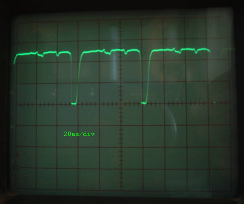
Jiri Dobry wrote:
> Alexander Haarer:
>
> Error E3 means that motor counter is out of range. Current SW need for
> thermotronic minimum 50pulses maximum 500pulses from end to end.
>

I believe that i found the problem. The software counts just the high
time of the photoeye pulse to determine the current motor speed.
 The Sparmatic Basic generates a signal with ~60mS High and  ~15ms Low.
The HR20 does just the other way round (shown at the logicanalyser pic
in svn)

attached is a screenshot


I changed the following - it seems to work for me, can please someone
review it ?

Index: F:/privat/sourcecode/atmel/openhr20/trunk/source/motor.c
===================================================================
--- F:/privat/sourcecode/atmel/openhr20/trunk/source/motor.c  (revision
260)
+++ F:/privat/sourcecode/atmel/openhr20/trunk/source/motor.c  (working
copy)
@@ -406,7 +406,7 @@
     }
   #endif
     // motor eye
-    // count only on HIGH impulses
+    // count  HIGH impulses for HR20 and LOW Pulses for THERMOTRONIC
 #ifdef THERMOTRONIC
     if ((PCMSK0 & (1<<PCINT1)) && (((pine ^ pine_last) & (1<<PE1)) !=
0)) {
 #else
@@ -415,7 +415,7 @@
         uint16_t dur = motor_diag_cnt - last_eye_change;
         last_eye_change = motor_diag_cnt;
 #ifdef THERMOTRONIC
-        if ((pine & _BV(PE1))==0) {
+        if ((pine & _BV(PE1))!=0) { //
 #else
         if ((pine & _BV(PE4))==0) {
 #endif
Ronny H.:

I thing that I found solution for delayed motor eye after motor stop. It
is not on SVN now, because it need testing. (If you want to have patch
send me email)
This solution make code shorter and it is possible port to first
generation of SW.

Possible delay after motor stop is from 0.1 sec till 4.2 second
!!!!!!!!!!!!!!!! WARNING !!!!!!!!!!!!!!!!!

rfmsrc branch revision 265 is experimental support for count pulses
after motor stop. It is not fully tested, if you want almost stable
version please use Rev 264.

Ronny H.:
You are found real problem, with counting pulses after motor stop it
have better precision, because it normaly lost few pulses. Please try
Rev 265.
I ha$s bad few weeks when I try found why OpenHR20 valves lost some one
second tick every day.
Current code (Rev 269) is almost fixed, but I thing that I found bug in
MCU.

Try code on
http://openhr20.svn.sourceforge.net/viewvc/openhr20/rfmsrc/bug_test/

It must show one '*' char every second (9600 baud). But if I use
synchronization sequence from Atmel datasheet, it miss massive volume of
1 sec ticks.
A am not sure bug is on my reading of datasheet or in MCU. Can you help
me?

Jiri
I was try to contact Atmel support for any solution and we will see.

Current code works on most of cases, but I know case when 1 second pulse
will be lost. After this RTC will be delayed. But it not happen on my
five valves on past 12 hours.
It is definitively MCU bug, see to
http://www.avrfreaks.net/index.php?name=PNphpBB2&file=viewtopic&t=29418
It is common to many AVR procesors (AT90CAN128, ATmega48/88/168,
ATMega32)

I will try found workaround for last remaining 1 second lost
possibility.

ALL: I am not abble to support first generation of SW. Can we mark first
generation as deprecated and use code based on rfmsrc tree? This code
can be compiled without RFM extension also. But I need port Thermotronic
patch into this SW. Any volunteer? I have not HW.
Hello Jiri and all Thermotronic users

I tried the last SVN Version with my old Thermotronic an get the
E3-Error mentioned by some others before. I tried, from which version
this issue exists: 122 seems to be ok - in versions from 124 to head I
get the error. Due to my job I don´t have enough time to check the
essential difference between the versions. Maybe someone can do this.
When the SVN Head rev. works fine with the Thermotronic I think it will
be not a big problem to put the changes into the rfm-branch.

Greetings, Thomas
@ Thomas V.:

E3 error on Thermotronic is caused by better motor eye noise protection
and inverse polarity of signal.

It was fixed by:
 Author:  Alexander H. (aha)
Posted on: 2010-01-15 14:47

I add this patch into SVN now, therefore you can use newest version.
Hello,

I struggled with the E3 error (on HR20!) too: I saw "Adap 1", then I
mounted the head to the valve for a short time the "Adap 2" was seen
(with little motor movement), then E3 occured.

In my case the reason must some noise in the adc temperatur conversion
(I extend the temperatur sensor with a 2,5m shielded cable): If I
disable the noise protection in uint8_t task_ADC(void)->"case 5"
completely, then all is ok.

Strange situation: If I put a "COM_print_debug(valve);" at the end of
"CTL_update" in controller.c (so that every second an output is
generated), the error was also away. Any explanation for this?

Ronny

@Jiri: because of these problems I started the test of your new motor
eye routines today evening...
@Ronny:
If you are abble to see E3 on current SW, plese send me log and
tracepoints (command "T00" to "T0d")

It is strange that ADC measure have some effect.
But if you want to disable ADC noise filter, you must not remove step 5,
but you must remove step 4 rename 5->4 and delete countent under
condition "if
((ad>dummy_adc+ADC_TOLERANCE)||(ad<dummy_adc-ADC_TOLERANCE))"
Hello Jiri,

here are logs from the current version.
Same procedure on both logs:
- flash the version without mounted valve
- mount valve
- wait for calibration end or E3-error
- read Tracepoints T00-T0d


I used the current version in the rfmsrc branch (but without RFM
compiled).
The log without the error is produced by uncommenting the following
lines in adc.c (:

//
//          if
((ad>dummy_adc+ADC_TOLERANCE)||(ad<dummy_adc-ADC_TOLERANCE)) {
                // adc noise protection, repeat measure
//                dummy_adc=ad;
//                state_ADC=4;
//                break;
//            }

I think, that produces the same result as you advised in your last post
(I used the easy way, I´m lazy :-)

The log with the E3-error is the original source in the rfmsrc branch.
But I saw also a strange effect (you can see it in the error log):
I couldn´t get the tracepoint T00-T02 and T0a-T0d !??? Nothing happened,
if I type  these Txx commands.


regards
Ronny

PS: What changed I additionally to the original source:
in Makefile I commented out the RFM switch
#CFLAGS += $(RFM)

in main.c (because I got errors about undefined values)
//FUSES =
//{
//    .low = (CKSEL0 & CKSEL2 & CKSEL3 & SUT0 & CKDIV8),  //0x62
//    .high = (BOOTSZ0 & BOOTSZ1 & EESAVE & SPIEN & JTAGEN),
//    .extended = (BODLEVEL0),
//};

in config.h I changed the #defines, because I got errors about already
defined values (RFM_WIRE_MARIOJTAG)


#define DEFAULT_TEMPERATURE 2000


#ifndef RFM
    #define RFM 0 //!< define RFM to 1 if you want to have support for
the RFM Radio Moodule in the Code
#endif


#if (RFM == 1)
#define RFM_WIRE_MARIOJTAG 0 //!< define that if you want to wire your
RFM to external JTAG pins
#define RFM_WIRE_JD_INTERNAL 1 //!< define that if you want to wire your
RFM to free internal pins

  #define RFM12 1 // just a synonym
  #define RFM_DEVICE_ADDRESS 0x00

  #if (RFM_WIRE_MARIOJTAG == 1)
    #define DISABLE_JTAG 1 //!< define DISABLE_JTAG if your RFM's
connection uses any JTAG pins
  #endif
  #define SECURITY_KEY_0    0x01
  #define SECURITY_KEY_1    0x23

nothing else, double checked with diff
@Ronny H.:
Which compiler version you use?
I must ask because this version is not able compile code with FUSES.
@Ronny H.:

It looks, that you valve need much bigger force to move. Could you try
it again with:

#define DEBUG_PRINT_MOTOR 1


You can also try set motor PWM limitation to bigger force (only for test
because touch on the end of motor range will be hard):

S0dff
S0eff

And expand tolerance for motor stop conditions (only for test because
touch on the end of motor range will be hard)
It is normaly 130% for calibration and 150% after. This values are how
much slow down is detected as motor end, this values is 180%.

S12b4
S13b4
Hi Jiri,

one question about init() function in main.c!

At line #04 and line #10 - Why are some PORTB pins set and then
immediately re-set again?
I think that doesn't make any sense.

01    //! Disable Analog Comparator (power save)
02    ACSR = (1<<ACD);
03
04    PORTB = (0<<PB0)|(1<<PB1)|(1<<PB2)|(1<<PB3)|(0<<PB6);
05    DDRB  = (1<<PB4)|(1<<PB5)|(1<<PB7);
06
07  DDRD = _BV(PD1) | _BV(PD6);
08  PORTD = 0xff;
09  PORTA = 0xff;
10  PORTB = 0xff;
Hello Jiri,

S0dff
S0eff

did the job! (you can see the log - same software version like yesterday
with E3-error: today without E3 error!)
But it is very, very strange, that the modifications in my post from
"2010-01-26 20:30 " also hide the E3 error! Some critical timing?

So I have to play with S0dxx to make a compromise between E3-error and
hard-touching the end, right?

All logs (also yesterday) were generated with "#define DEBUG_PRINT_MOTOR
1"

I use "avr-gcc (WinAVR 20090313) 4.3.2"


Some question (for my education):
How did you see, that S0d="min motor_pwm PWM setting" was the reason for
this misbehavior?
What means the output
+ 0610 fe
+ 0365 fe
+ 0332 fe
+ 0325 fe
+ 0316 fe
... ?

Thanks for your patience and very fast help!
Ronny
"+ 0332 fe"

"+" means walve open "-" means close

0332 if time between two eye pulses. Software try it control around
wanted value (G14 * 8). For this it change pwm

"fe" is actual pwm value (G0d and G0e are allowed min and max)
First experiences with OpenHR20E:

Day of installation: No problems.
The day after: Cold because of the window-function.

The problem: In the morning, our central heating goes up to 90°C. As
soon as a certain room reaches 20°C, the water temperature is reduced.
This results in a slight temperature drop which is interpreted as open
window (especially as the sensor is close to the radiator).

The vent closed and never opend again, because with a closed vent, there
is no rising temperature.

Besides: This is a problem in poor isolated bulidings, too. When a
window is closed, temperatures do not rise because there is nothing
around which is warm enough.

What about some kind auf "timer" to end the open-window-state after e.g.
30 minutes?


There was another problem which is related to too high motor current
which causes resets. This happens when I completely open the vent by
rotating the blue cogwheel before "plugging" the HR20 in. When adaption
starts, the motor is blocked immediately and it resets. This then
repeats endless.
Newer batteries help, but the "old" ones were fresh enough to get a good
contrast on the lcd and caused no problems with the original HR20e.

Maybe some kind of soft start could help here? Especially when opening
the vent, there is not much force needed (at least for me).


I plan to buy and flash some more units soon, especially the rfm12 thing
is very interesting.
@Chris:
First generation of SW not support anything like window open timeout.
Please use rfmsrc branch and compile it without RFM support ("make
RFM=-DRFM=0")

Window open function you can modify by this setting:

/* 23 */ uint8_t window_open_detection_diff; //!< threshold for window
open detection unit is 0.1C
/* 24 */ uint8_t window_close_detection_diff; //!< threshold for window
close detection unit is 0.1C
/* 25 */ uint8_t window_open_detection_time;
/* 26 */ uint8_t window_close_detection_time;
/* 27 */ uint8_t window_open_timeout;           //!< maximum time for
window open state [minutes]

For other setting see too eeprom.h

This settings can be changed from service menu (press&hold all buttons)
or you can use "S271e" (example: set timeout to 30 minutes) serial
command.

I have not any problem with batteries and reset when motor starts. You
could modify start up current when you decrease "max pwm" setting \, but
you will risk that force will not sufficient to motor start.
Hello,

I had the same problem as Chris with the window open function. I just
disabled it in the code as it's not a big deal to reduce manually the
valves when you shortly open the window.
You can comment out the call to the function CTL_window_detection in
controller.c (it's in the CTL_update function).
Since then I don't have any problem with the thermostats.

Manu
Hello,

I have ported the Thermotronic changes to rfmsrc (rev 272). I didn´t
have much time to test, but it seems to work. RFM-features for
Thermotronic are not implemented, but I think it could work with a
different pinning in main.c.

@Jiri: I will send you the changed files by email

Thomas
Thanks to  ThomasV we have THERMOTRONIC patch for rfmsrc based code.
Therefore I can move old main trunk into archive and support only second
generation of SW (rfmsrc based)

Any objection to this step? If no, I will do it tomorrow.

Jiri
Hi!

I have a problem with the initial sync from rfm-master to HR20e. My
HR20e using jiris internal rfm12 wiring but my HR20e doesn't sync with
rfm-master.

So i check the sync packets coming from rfm-master with another homemade
test-receiver (µC m168 + rfm12b module). My test receiver using the same
RFM_init (Conf., FIFO, Freq., AFC...). The receiver gets the sync
packets correctly. (don't worry about the date, it's only for testing)

rfm-master sends sync packet
06.03.10 15:28:00 8B 0A 30 CF 38 00 00 D3 ...
06.03.10 15:28:30 8B 0A 30 CF 39 00 00 3D ...
06.03.10 15:29:00 8B 0A 30 CF 3A 00 00 28 ...

test-receiver gets sync packet
06.03.10 15:28:00 8B 0A 30 CF 38 00 00 D3 ...
06.03.10 15:28:30 8B 0A 30 CF 39 00 00 3D ...
06.03.10 15:29:00 8B 0A 30 CF 3A 00 00 28 ...


But my HR20e gets sync packet
06.03.10 15:28:00 8B 4A 30 CF 78 40 40 D3 ...
06.03.10 15:28:30 8B 0A 70 0F 39 40 00 3D ...
06.03.10 15:29:00 8B 4A 30 CF 7A 40 40 68 ...

What i see - some correct packet bytes, but others have a 0x40 offset.
The first packet byte 0x8b (rfm_framebuf[0] -> sync pattern + packet
site) always seems to be ok.
I changed the rfm12 frequency (original 868.35 Mhz) but the problem
still exists. I didn't change the orginal RFM_init parameters (AFC, Data
Filter, RX control,...) in openhr20 source!

What's the problem? Wrong rfm12 tuning in my HR20e? Any suggestions?

Note:
First 8 bytes of rfm packet were printed with additional debug command
and output of rfm_framebuf[i] in COM_commad_parse() OpenHR20\com.c
e.g.
case 'G':
   for(i=0; i<8; i++) {
      print_hexXX(rfm_framebuf[i]);
   }
   break;
@Marko B.:
Do you have this problem only on one valve of more?
At this moment I don't have any idea.

Here are you connect ground and VCC for RFM module in valve?
Do you crop properly original PE6 connection?

Jiri
Attached files:
-

pic.jpg
62 KB
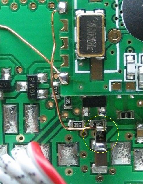
Hi Jiri!

Currently i only have one valve with rfm12.
Yes, i cropped the PE6 connection. I will check Vcc, GND and PE6 again.

One question about soldering DATA/nFFS:
Is DATA/nFFS soldered with SMD104 (100kΩ) or with 58C left side (inside
the blue circle) and SMD104 to 58C right side? I can't see the solder
connection exactly.
The circuit diagram says DATA/nFFS to 100kΩ.
DATA/nFSS if connected only too 100k rezistor and oposite end of this
resistor is connected to VCC

I known that it is not clear from picture, but it is clear in schematics
Hello,
I'm new to this forum and i want to congratulate your for this marvelous
work.

I own 3 HR20 bougth in germany as it is really expensive in France (more
than 55€ each!!!) and one of them has something that look like the
trouble described above: the heater stay cool even if the temperature in
the room is below the programmed value.

I need to flash it with your firmware but i must confess that i'm a bit
lost.
I have an avr dragon and avr studio as i work already with avr but
usually with bascom and i don't really know anything about the other
compiler.

I've read the entire thread (the english part) and i've never found any
wiki or comprehensive instruction on how to do it.
I've also try to understand the german part but even with google
traduction it's difficult to read.

So i've a few question and i apologize if the information is easylly
available and i didn't find it:
-the hr20.hex and hr20.eep found in the repository visibly take into
account the rfm12 wath happen if i use this software without this part
of hw?
-is there somewhere a complied version up to date without the rfm12
part?
-is there a guide of the configuration of the hr20 (i mean temperature,
time with the buttons and wheel) after the flashing?
-is there a precompiled up to date version of the openhr20suite to
facilitate configuration?

thanks in advance
stephane
@ssaul
the attached files are compiled from the current version (275) without
rfm-support.

@all: I think, I´ve found some cosmetic errors, if I compile without
rfm:

in config.h:
the 2 defines
#define RFM_WIRE_MARIOJTAG 0 //!< define that if you want to wire your
RFM to external JTAG pins
#define RFM_WIRE_JD_INTERNAL 1 //!< define that if you want to wire your
RFM to free internal pins

should be after "#if (RFM == 1)"
without that I got several warnings about redefinition - and in my
opinion it makes sense to move rfm-definitions in the RFM part


in ../common/rtc.h
in line 575 and 681 the variable should be inititlized: next=0, else I
get warning about uninitialzed variables
Last SVN revision have changes to remove possible warnings.
Problem is, that some warnings can't be removed.
Example is uninitialized variables. In this situation I need it
uninitialized, because "random" contend will be overwriteln, but
compiler cant see it. Add initialization is possible, but it need flash.
We must save each possible flash word.
MASTER code for RFM extension is updated to "Macro G" hardware.
LED light time is extended to 0.3sec It make it visible easy. Real sync
or RX is too short.
OOOPS. New master hardware is here
http://embdev.net/topic/158895#1533392

And author is Marko B.  (sorry Marko)
Yesterday night I was salami instead of brain. Author of master PCB and
new version of HW is Marco G. I am verry sory Marco.
Is there anything special to do to get the rfm12 working?
I used the current rfmsrc, defined external connection (jtag-pins) and
set device ID from 00 to 01 to enable wireless.

How can I see if connection to the rfm12 module works?
Is ist supposed to transmit or does it wait for packets from the master
board (I did not build it yet...).

Using a radio scanner, I did not hear any transmissions (except of many
other 433Mhz devices and my other rfm12 plattforms...).

BTW: The window-function seems to work ok now for me, at least there are
no false positives.

Chris
@Chris: current rfm12 varian can't work without "master" board.
I solved my problem with the initial sync from RFM-master to HR20e.
I can't say why this problem occures. Maybe a fragile/unwanted solder
connection or something like that.

I made a little modification of the internal wiring. Connection of my
rfm12 is a mix of internal and external wiring scheme. All connections
and rfm12 are still inside. It is easier to solder than m169 pins.

Vcc        - internal Vcc
GND        - internal GND
DATA/nFFS  - internal 100k-Vcc
SDO        - int. wire to ext. connector pin2(PE2)
nSEL       - int. wire to ext. connector pin3(TMS)
SCK        - int. wire to ext. connector pin4(TCK)
SDI        - int. wire to ext. connector pin5(TDO)

My rfm-master (crumb168) and wireless hr20 are working quite well.
I just updated my HR20 to the opern source firmware, because i had
problems with the full-movement mode of the original software. My
original software did not allow me to enable this full-mode.

But now, i think the usage is a little different, than in the original
software.
Is an open-source-user-manual available ? Where can i read the usage?
@AntonMayer

What do you mean with "full-movement mode"?
At this time no manual exists... the usage can be determined from the
source
AntonMayer: you probable mean full stroke mode.
OpenHR20 don't have it, but have something better. You can set valve
position manualy. How? Unmount HR20, close valve manualy, press&hold "C"
button, mount H20 back and release button after it.
This setting can be also changed manually on service menu
Yes, i mean the full stroke mode.
My problem is that i have no idea how to use the new software.
Can someone help me with openhr20 + rmf12(433) + master, please?

I flashed my hr20e and connected rfm12 (433Mhz, not the new b-version)
to the external jack. I changed the id from 0 to 2 and configured it to
external rfm12.

I build the master board as shown in layout version 5, flashed and set
fuses.
I connected the master board to a com-port and opened a terminal
application. On power on I can read the version-string, after that it
outputs sequences of numbers and =?.

The leds on the master-board do not light (except very short at power
on) and hr20 displays E4 after some minutes.
Sometimes I can read something like "ERR000".

Where is my mistake?
Thanks :)
Hello Chris,

you must have run the deamon. He send the OpenHR20Master the time for
synchronisation until it's done ,you will nerver see any data from the
HR20.

Ronny
Hello,

I want to change the temperature sensor to a ds1820 1-wire device
(because I need more than one temperature per device). Therefore I rely
on a good calibration of the rc-oscillator. I saw in the main.c
init-routine a "todo" for that. So I made a new one. I coded the
"measurement heart" in assembler, so that the compiler can´t change it.
The codesize is about 60 bytes. Maybe someone need it too and want to
put it in the svn:

Ronny
1 | void calibrate_OSCCAL(void) |
2 | { uint8_t temp; |
3 | volatile uint16_t Z;// very important volatile define |
4 | |
5 | CLKPR = (1<<CLKPCE); |
6 | CLKPR = (1<<CLKPS1); // set the CPU Frequency to 2MHz |
7 | ASSR = (1<<AS2); // set 32,768kHz osc as source for timer2 |
8 | TIMSK2 = 0;// disable any interrupt sources |
9 | TCCR2A = 1;// start timer |
10 | |
11 | while(ASSR & (1<<TCR2UB)); // wait for TCR2UB to be cleared |
12 | |
13 | _delay_ms(500); //important delay for stabilize the crystal !! real: 1s, because FOSC=4MHz but we set 2MHz |
14 | |
15 | TCNT2 = 0; // reset TCNT2 |
16 | temp = 127; |
17 | |
18 | for(;;) |
19 | {
|
20 | temp--; |
21 | OSCCAL = temp; |
22 | |
23 | Z=0; |
24 | TIFR2 = 0xFF; // reset counter |
25 | |
26 | // wait for the compare-match on timer2: while ( !(TIFR2 & (1<<TOV2)) ) {Z++;}
|
27 | asm volatile ( |
28 | "jmp1:" "\n\t" |
29 | "adiw %A0,1" "\n\t" /*2 cycles*/ |
30 | "sbis %[tifr2],0" "\n\t" /*1 cycle*/ |
31 | "rjmp jmp1" /*2 cycles*/ |
32 | : "+e" (Z) /*input and output*/ |
33 | : [tifr2] "I" (_SFR_IO_ADDR(TIFR2)) |
34 | : "memory" |
35 | );
|
36 | |
37 | if (Z<(3125+5)) break; |
38 | }
|
39 | return; |
40 | }
|
I got it running with the master now. This is a quite cool thing :)

However, it sometimes looses sync or misses transmissions. Distance is
not too far and the rfm12 modules I use in my other projects seem to
reach further.... Maybe reducing the data rate would help (I'm using
rfm12 without "B" at 433Mhz).

I think any window-detection feature is useless:
When I open the window, it needs some seconds to detect it and to close
the vent.
After the vent is closed, the heating stays warm/hot because it needs
much more time to cool down.
When I come back to close the window (let's say after 5 minutes) it's
still warm/hot. So it does not save energy here :)
After I close the window the heating gets cold and openhr20 opens the
vent after 90 minutes because temperature does not rise without heating.

So no matter how you configure it: It does not work for me. If you open
the window for a long time (maybe 30 minutes or longer) it is usefull.
But then the walls cool down which is not very efficient.


My aim was to provide a feedback to the central heating about the vent
positions and actual/wanted temperatures in our house so that it can
rise water temperature in the morning until rooms are warm and so that
it can lower temperature if temperatures should be reduced because no
one is at home.
I guess the trick is that without the window open detection, the
temperature sensor would recognise the fall in temperature (well it does
always) and the algorithm would open the valve completely.
So it's better to close the valve and jst loose the energy already
stored in the heating.

Isn't there a button one can press while closing the window to force the
OpenHR20 to end the window detection?

I haven't managed to flash the OpenHR20 firmware on my valves yet,
moving costs far too much time :(
>I want to change the temperature sensor to a ds1820 1-wire device
>(because I need more than one temperature per device). Therefore I rely
>on a good calibration of the rc-oscillator.

Why that ?

Timing for 1-wire is extremely wide, the difference between fastest and
slowest has a factor of two.

If 1-wire does not work it is definitely not due to a bad
RC-calibration.

Axel
Hello,

i flashed my Hr20 and built a Master. But i seem to be not able to get
the master-software running on my PC. Maybe someone can explain step by
step for windows xp or opensuse:
Which software do i need?
Which config files do i have to change?

Thank you very much!
@ Marco G.:
I think if you manually change temperature by moving the wheel it leaves
open window mode.

@ OpenHr20-Fan:
You need a webserver (like apache2) with php-support (version 5),
php-cli for running the daemon.php from command line, sqlite for the
database and php-sqlite for database access from php.

Copy the files and folders from www to the directory your webserver uses
for the websites (/var/www on Debian Linux).
Copy the files from tools to another location.

Take a look at the files config.php, daemon.php and create_db.php and
edit the location of the sqlite database (dont place it in the /var/www
directory of apache...).
Create the database by running create_db.php.

Configure com-port (Debian: stty -F /dev/ttyUSB0 38400). You can also
include this command in daemon.php:
exec('stty -F /dev/ttyUSB0 38400');

Start daemon.php on command line.
Go to the webinterface (localhost/index.php).
Hello together,


I'm new to this list. I found this project, because I get a complete new
heating system in my house.

I've tried a first test with openhr20 software, and I think it is a very
well done and well documented project. Thanks to all :-))

For my purpose, I want to realize a network of all my HR20 via RS845.
I've seen , somebody has thought about this, but nobody has realized it
now.

Is somebody intrested in this new part of the project ?

I've some ideas what can be usefull, but somebody may have additional
ideas.
First ideas:
- connection of the HR20 with a 4-wire cable for RS485-bus and 5V power
- a little hardware for the HR20 with 3V Voltage regulator and RS485
driver
- advanced communcation with adress parts
- connection to a PC via an RS485 - USB adapter

best regards

Wolfgang
Hello Wolfgang,

I would be interested in a solution with an RS485-bus (using the I²C
interface) connected to multiple HR20E. For power supply and data
transport, I have wires at each HR20E in the wall.

The problem is, that I have not much time, todo much work on this
project.

ELV has developed a new series with remote interface, remote window and
dore switches and USB stick for remote access via PC (see
http://www.elv.de/Funk-Heizungsregler/x.aspx/cid_74/detail_1/detail2_1361).
I am not sure, whether it is worth the time to develop an own solution
although it has some advantages (specially the WEB Server solution).

Regards,

Karim
Hello Karim,

I want to adapt the HR20 via the 10 pin connector, using TxD and RxD and
the PE2 port to switch the direction of the RS485-driver. I've develope
a small board, but I'm still waiting for some parts to start the test
(If I have finnished the hardware-test, I will post it here).

I will do the project, with or without help from other users, but Ideas
and help is welcome :-)

The ELV-products are based on communication via RF, and I don't like to
much RF-activity (there is enough electro-smog in the air)! The other
advantage of wired connection is no need for batteries !

best regards

Wolfgang
Hello,

Is the HR20-style the same electronic like the HR20 ?

best regards

Ronny
Hi,

Has there been any further developments with new firmware revisions ?

Wolfgang, did you make any progress with RS485 ?

Thanks


Stuart
Hi!
I'm using the openhr20 firmware with two of my rondostates because with
the original firmware, vents do not open to 100% after a few days.
Openhr20 works perfectly :)
I only had to disable the window open detection because it kept on
triggering when no window was open.

I'm also using the serial port to get temperatures and valve position.
I noticed the following:
On rondostat 1, the baud rate is 9600 which is correct.
On rondostat 2, the baud rate is 10416.
@Chris:

On rondostat 2 you have wrong internal oscilator calibration value.

Jiri
Hi,

can someone send me the latest, non RFM12, HEX and EEP files ?

I will only flash my HR20s. I'm not interrested in programming and
compiling. I will try to flash my HR20s with an free ISP-Programmer.

Thomas
Attached files:
-

P1000256.jpg
330 KB -

P1000258.jpg
340 KB
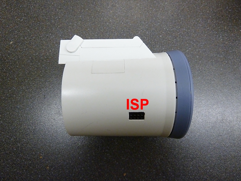
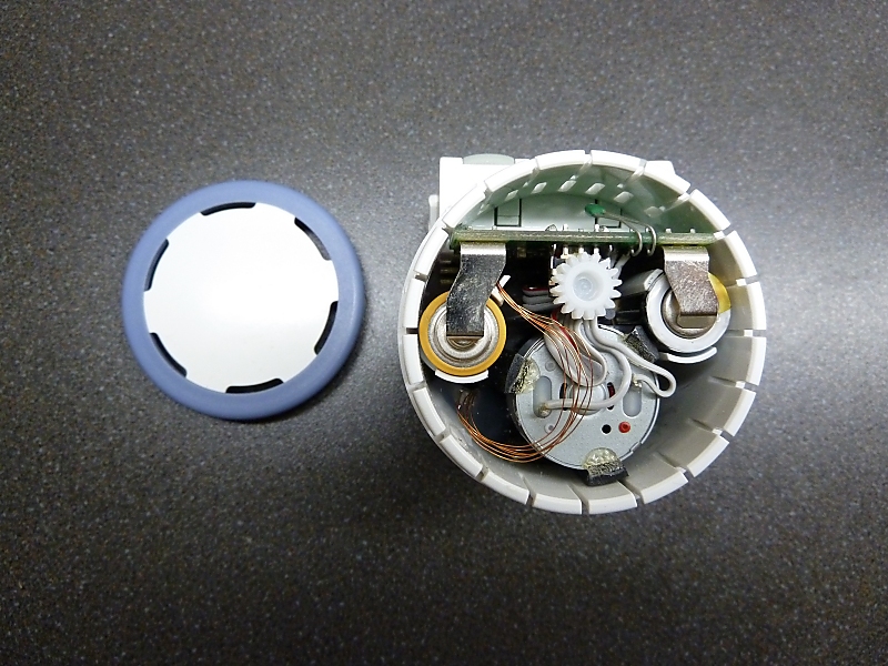
Hi,

just successful flashed my first HR20 to OpenHR. Works well. It was that
easy ;-)

But, is there a litte description of the functions, a manual or
somethine else available ?  Ich understand most of the dsiplay output,
but still some questions.

I've added an externel connector for the ISP. It took some thime to do
this.

Thanks to Jiri, who send me the HEX-Files :-)

Thomas
Control is almost compatible with original SW with some features.

man difference:

middle button can show actual time, actual temperature and valve
position (0-100%)

press&hold middle button can set 4 preset tempeteratures

press&hold AUTO/MANU = time setings

press&hold PROG = assign preset temperatures to time ( it have one
program for 1-7 or individual for each day in week)

Press & hold all button show service menu.  It have 2 modes switched by
middle button. First mode is internal settings (see too
http://openhr20.svn.sourceforge.net/viewvc/openhr20/rfmsrc/OpenHR20/eeprom.h?revision=273&view=markup)
Second is is some diagnostic values


PS: why do you not use JTAG? It don't need modification and it is cheap,
example here
http://cgi.ebay.com/ws/eBayISAPI.dll?ViewItem&item=200549194321 15.90USD
Hi Jiri,

some examples :

Ad 1 to 3 - calibration ?
E 2 - HR20 not connetcted to valve ?
E 3 - ???
OPEn - Window open ?
- C - ???
* - Freeze-protection ?
( (moon) - Nighttime/-temperatur
o (sun) - Daytime/-temperatur
( and o (both symbols) - ???

After first flashing, I get "EEpr" in the display. Don't know why, after
second frashing, the problem was solved.

Sorry, I don't understand the service menue and your program. I'm not
firm with C :-(

JTAG:
Hmmm, I'm normally using BASCOM as programming. This is also the reason
why I ask you for the HEX-files. My programmer is the "Sample
Elektronics Programmer", only 5 wires from parallel-port-interface. I
have a mySmartUSB light too, this device operates with BASCOM and can
program HEX-files for standalone too. I never found an cheap programmer
which is compatible with BASCOM.

Edit:
How can I activate RFM for later usage ?  Must the programm recompiled ?
Must the RFM12 be connected, when I'm not using RFM ?

Thomas
Hi Thomas,

you're right,
Ad 1 to 3 - Adaptation to mechanic valve
E 2 - HR20 not connected to valve (like original firmware)
E 4 - wireless HR20 out of sync
OPEn - Window open

* - Freeze-protection temperature
( (moon) - Nighttime/-temperatur
o (sun) - Daytime/-temperatur
( and o (both symbols) - "comfort" temperature

You can set 4 different temperatures, that's why there are 4 symbols :)
Hi,

what does "comfort"-temperature mean ?

Thomas
No special meaning, it is Jiri's expression for a third temperature
level :)

You may want to set it 2°C higher in the evening than during the day,
that's what it's for...
Hi.

Problem :

I can set 4 temperatures. Fine !

But I only can set times for 2 temperatures :  ( and (o

Ok, the * is for the frost-protection, but when is o active ?

Thomas
Hi Thomas,

I just tested it:
- press&hold PROG to switch to scheduke programming
- press prog again to set same schedule for each day
- adjust the time using the wheel
- adjust the temperature level using the temperature button.

For me, all 4 levels can be choosen here.
Hi Marco,

That was the tick ! ;-)

Adjusting temperature levels IN the time-programming menue !

Thanks a lot :-)

RS232:
Protocol ist 9600,8,n,1, correct ?
If I connect a second AVR (3V Vcc) on the RxD & TxD, must I convert the
signals ?  Or is it possible to connect it directly ?

Thomas
you're welcome :)

9600 8N1 is correct, as far as I can see from the code.

I think you can connect it directly, you just have to swap Rx and Tx.
The voltage levels on HR20 side are also about 3 V, i.e. two batteries.
Maybe you want to add 1k series resistors as current protection.

In the service menu (press&hold all 3 buttons) you can edit the EEPROM.
The contents are shown in Jiri's link above
(http://openhr20.svn.sourceforge.net/viewvc/openhr20/rfmsrc/OpenHR20/eeprom.h?revision=273&view=markup)
in line 51-91.

The 2 digits in front of the colon are the EEP address, the last two
digits are the value. PROG switches between address and value. Changes
are saved when switching back to address (I'm not 100% sure about that).

greetings
Marco
Thanks Marko G for more information. I must add only one

E3 - is invalid mechanical calibration (too short range or too long
range) Same as original SW

Mechanical range of valve can be calibrated manualy. see to my post from
2009-04-01 10:07

"EEPr" - EEPROM not contain valid settings
Hi Thomas,
   do you have a schematic for your ICSP port ?

delboy
Attached files:
-

169.jpg
240 KB
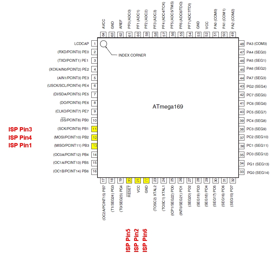
Hi,

it's standard ISP to processor. I use the 6-pin ISP. All pins of the
processor going to a via of the pcb. I soldered the wires on ths vias.

Thomas
Hi all,

great so see this project still active.

I'm using 4 OpenHR20 Rondostates now, but I still have problems with the
open window detection.
How can I turn it of? I set 0x22 to 0xFF and 0x24 to 0xFF, but it still
shows "open".

@Knickohr: You can connect an external avr to the rondostat, it works
without problems.
Hint: OpenHR20 sends out a status every 4 minutes. I use it to wake an
external avr from power down mode (connected TX of the rondostat to RX
and external interrupt pin of my atmega8). It wakes up fast enough to
get the serial.
@Chris: version of your SW? Best could be SVN version number.
Hi Chris, hi Jiri,

I have the same problem with the Open Window.

Don't know, which SW-version. You send me the HEX-File ;-)

Thomas
Window close detection - disable:
set 0x23 to 0xFF (for SVN revision != 281 can be different index see too
http://openhr20.svn.sourceforge.net/viewvc/openhr20/rfmsrc/OpenHR20/eeprom.h?view=log&pathrev=273
)

If you have problem with noise from motor, you can disable
allow_ADC_during_motor (setting  0x28 = 0x00)
for normal trunk setting map see too
http://openhr20.svn.sourceforge.net/viewvc/openhr20/trunk/source/eeprom.h?revision=232&view=markup
Attached files:
-

ponyprog_sch_220R.jpg
57 KB
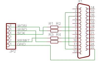
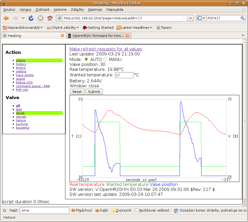
So I used this simple LPT ICSP circuit with avrdude on windows and it
worked (btw 220R resistors).
I connected MISO, SCLK & MOSI to some vias near the screw and the GND
and RESET to the ISP port.
These are the dos commands :-

install_giveio.bat
avrdude -p m169 -c stk200 -P lpt1 -U
flash:w:"D:\Rondostat\openhr20\trunk\source\hr20.hex":a -F

avrdude -p m169 -c stk200 -P lpt1 -U
eeprom:w:"D:\Rondostat\openhr20\trunk\source\hr20.eep":a -F

I couldn't read any of the fuses, so I decided not to try and program
them, but I fired it up and it WORKS !!!

Next stage is to get some cheap Oventrop adapters and rfm12 modules.
Hello.

Where can I get the c-code (or some more informations) for the software.
Every link will bring me to a blank page.

Thanks a lot,
Turtleman
Sourceforge SVN is down

Yesterday our vigilant operations guys detected a targeted attack
against some of our developer infrastructure.  The attack resulted in an
exploit of several SourceForge.net servers, and we have proactively shut
down a handful of developer centric services to safeguard data and
protect the majority of our services.

see too http://sourceforge.net/blog/sourceforge-net-attack/

Please wait.
With AVR-GCC 4.5.2 and avr-libc 1.7.0 on Archlinux i've got several
errors regrading fuses like this:
'CKSEL0' undeclared here (not in a function)
the header-file only declares FUSE_CKSEL0. After i changed that the
software compiled.

---snip---
Index: main.c
===================================================================
--- main.c  (Revision 281)
+++ main.c  (-)
@@ -334,9 +334,9 @@

 FUSES =
 {
-    .low = (uint8_t)(CKSEL0 & CKSEL2 & CKSEL3 & SUT0 & CKDIV8),  //0x62
-    .high = (uint8_t)(BOOTSZ0 & BOOTSZ1 & EESAVE & SPIEN & JTAGEN),
-    .extended = (uint8_t)(BODLEVEL0),
+    .low = (uint8_t)(FUSE_CKSEL0 & FUSE_CKSEL2 & FUSE_CKSEL3 &
FUSE_SUT0 & FUSE_CKDIV8),  //0x62
+    .high = (uint8_t)(FUSE_BOOTSZ0 & FUSE_BOOTSZ1 & FUSE_EESAVE &
FUSE_SPIEN & FUSE_JTAGEN),
+    .extended = (uint8_t)(FUSE_BODLEVEL0),
 };

 /*!
---snip---

I used the 10-Pad-Connector on my Sparmatic (Thermotronic) Basic and it
seems mostly working. Sadly they used PE1/TXD for the motor-eye on this
model so without PCB-hacking no EIA232 for me but there is SPI on the
10-Pad-Connector (pins shared with buttons!) and TWI/I2C/Whatever on
JP6.
Hi Jiri,

I did not manage to turn of the window detection...
I dont know the svn revision, but in eeprom.h it says:
1 | /* 22 */ uint8_t window_open_detection_diff; //!< threshold for window open detection unit is 0.1C |
2 | /* 23 */ uint8_t window_close_detection_diff; //!< threshold for window close detection unit is 0.1C |
3 | /* 24 */ uint8_t window_open_detection_time; |
4 | /* 25 */ uint8_t window_close_detection_time; |
I set all to 0xff or as high as possible, but it still displays open.

Chris
Hi Jiri,

I just saw that the rfm12-code (\openhr20\rfmsrc\OpenHR20) differs from
(openhr20\trunk\source). Which one should I use when I do not need
rfm12?

Chris
Please log in before posting. Registration is free and takes only a minute.
Existing account
Do you have a Google/GoogleMail account? No registration required!
Log in with Google account
Log in with Google account
No account? Register here.