I looked through the HR20 threads last weekend and I have to admit you
did a great job.

I have some questions which I don't understand at the moment:

Is there a cyclic (e.g. once every quater) full open and close of the
valve implemented to keep it movable?

Window open and close seems to be detected by a reduction of the
measured temperature. Is the RF protocol able to created a mashed net
where a window sensor talks to one or more valves?

Is there free flash space left to extend the S/W?

Is a low battery indication / battery voltage transmitted to the master?

Cheers,
Knut
Hi Knut,
Knut Schwichtenberg wrote:> Is there a cyclic (e.g. once every quater) full open and close of the> valve implemented to keep it movable?
there is, AFAIK every Sunday at 12.00
> Is a low battery indication / battery voltage transmitted to the master?
yes, the battery voltage is transmitted to the master
The other questions have to be addressed by Jiri, I'm not sure about
them.
Greetings,
Marco
H Marco and Jiri,

thanks for your replys. @Jiri the following questions from my first
email remain unanswered by Marco:

Window open and close seems to be detected by a reduction of the
measured temperature. Is the RF protocol able to created a mashed net
where a window sensor talks to one or more valves dirctly?

Is there free flash space left to extend the S/W?

Cheeers,
Knut
@Knut Schwichtenberg:

Current wireless network is not "mesh" but star topology with one
master. Free space in flash is problem (0.5kB free), but we can remove
some low priority code (watched variables in service menu, 0-24 bars in
LCD, in extreme situation we can remove local serial line communication
in wireless case)

This is my TODO list for this project:

- optional window contact wired to PE2 signal on valve (time: 1 week, I
must mount magnetic contact where it is possible)
- add command to "block" valves remotely = remote childlock (time: 1-2
months)
- change wireless protocol. I remove fixed communication windows and I
will use random access with collision detection. It will improve
communication speed and allow add wireless items without RTC and signal
repeaters (time: 2 weeks - 3 months)
- add more sensors into wireless network. Examples: remote window open
contact, humidity sensor, int/out temperature, door sensor for automatic
heating switch on. (time depend to PCB availability, probably end of
Feb)

Jiri
Some more information about wireless "extension" board:

- ATMEGA16 / ATMEGA32 CPU depend to destination
- RFM12b

- optional SHT21 humidity/temperature sensor
- optional DS18S20/DS18B20 temperature sensor
- optional FTDI FT232RL USB, this PCB can act as master board
- optional LE33 stabilizer (3v3 power from USB, optional if 50mA from
FTDI is not sufficient or for VUSB)
- optional VUSB interface (http://www.obdev.at/products/vusb/index.html)
- optional I2C EEPROM (24c02 - 24c1024)
- optional LCD from Nokia 3310 with optional backlight (LCD is low
power, visible without back light. Destination for show temperature or
status)
- optional power from 2xAA or 1xLipol
- it have I2C and SPI on connector
- 7 A/D free lines in connector or 7 digital I/O
- PCB size 50x50mm

Today evening at home I will store schematic and PCB layout into SVN.
PCB layout is done, but I must wait for china spring festival end
(Reason is price, PCB from http://www.seeedstudio.com is 5x cheaper than
from local sources.)

NOTE: this board have RFM22/23 option, but it can't be RFM12 compatible
on wireless, it is for another project.
Note for window detection:

Temperature slope is not, and can't be perfect solution for window open
detection.

Reasons:
- in some situation, depend to air flow in room, temperature fall is too
slow. (in my bedroom detection take 2-3 minutes and can't be improved,
unacceptable, reason is balcony door on side to heating)

- sometimes heating is far from window, temperature fall is extremely
slow and hidden by radiator heat (example: my bathroom)

- cold air stream from window with bad thermal isolation can create
false window open positives (my kitchen)

In reality, I have only 2 rooms, where window detection works fine. In
other cases, I don't have any idea how to improve it only with
temperature. I have long series of temperature measurement and it is
sometimes difficult to detect window open for human, impossible for
computer. This is reason, why I will use magnetic window contact.
@Knut Schwichtenberg:
I am using something similar to this project (Igor Cesko IR receiver).
But VUSB is little bit more "adu1t" and maintained project. And we have
not any problem with license. OpenHR20 is also GPL project,
documentation is also available.
Wireless Expansion board layout is in repository. You can check it.
NOTE: SVN web interface on SourceForge.net still offline. You must us
SVN directly:
1
svn co https://openhr20.svn.sourceforge.net/svnroot/openhr20 openhr20
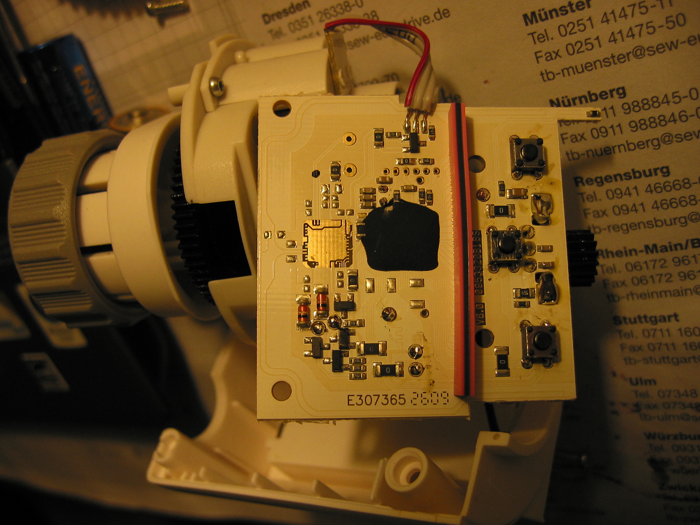
Some more notes about Thermotronic:
The "TWI/I2C/Whatever"-Port i mentioned earlier (JP6 at
<http://www.mikrocontroller.net/attachment/29357/schematic.png>; ) is
actually grounded near the soldering-points - i had to cut this
connection to make the pins useable. Another thing i noticed: Makefile
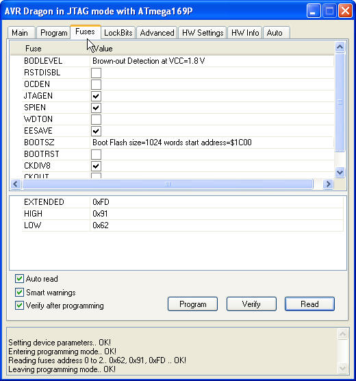
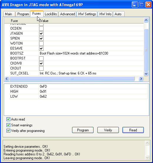
says F_CPU = 1000000 but my fuses are set to 8MHz (no CLKDIV) and i'm
pretty sure i didn't change this…
I got the code.

I want to test the hr20 first without a wireless module.
So what means

"make RFM=-DRFM=0"

How can I compile the software without rfm?
Is it ok to define RFM = 0 in config.h? (line 102, rev. 278)

By the way. Where do I find the rev. number of the actual software
version.
It's true that I'll find the newest version in \openhr20\rfmsrc\OpenHR20
In config.h revision seemed to be set to 278 but I heard something about
rev 281.

Thanks,
Thomas
Thomas Pehmöller wrote:
> So what means>> "make RFM=-DRFM=0">> How can I compile the software without rfm?> Is it ok to define RFM = 0 in config.h? (line 102, rev. 278)
Thomas,
make is a kind of scripting. The command line sets the variable RFM to
the value "-DRFM=0". I expect from the normal makefile behaviour this is
forwarded to the C-compiler's command line. "#define" in a file are
overwritten by identically named "-D" command line parameter. So the
make command line and your finding are identical.
Cheers,
Knut
What are your experiences ?

Let's assume the system (radiator and HR20) are in a stable state...

What accuracy (room temp. e.g. 22°C) is typical for the original
firmware and the OpenHR20 firmware ??
Thermotronic: Ctrl+Z for 8MHz - There was a bug in the fuse-gui i'm
using - original at 1MHz was correct. Got basic i2c in but some
(timing?-)problems. Getting my measurement-tools back next week and
hopefully also some time to look after that.

@Richard G. I guess since the temperature inside your room varies even
if your radiator would keep a constant temp thats mostly negligible
Hi to all the Pros here ... lot of work done here ... really impressive
!!!

The HR20 will be my first AVR project ... I'm comeing from the
automation business, but have not done any C-programming for the last 10
years ...

So far I bought myself an AVR Dragon board, installed AVR Studio and
then WinAVR.

I have read through the original german and this thread. I also do not
need wireless, but want do use this branch, as it is the only one
maintained.

I want to do 2 things:
1. Flash the latest File from yours to check if I can handle the
hardware (dragon, cabeling, hr20..) ... please tell me which file I
should use

2. If that works I want compile the source myself and make little
changes... Do I need SVN - I never used it before - what do you suggest
the rookie   ... ;-)
Hello,

After long, long, long time I made release of version 1.0.

See here https://sourceforge.net/projects/openhr20/files/

This zip contain binaries for all supported configuration options.

last change except bug fixes is option for hardware window detection.

Jiri
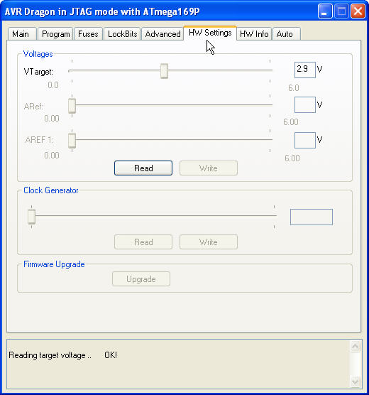
Richard G:

For programming/debug you need ICE (you can use AVR ICE, AVR ICE mkII,
AVR Dragon, AVR ONE) I recommend AVRICE first generation clones, it is
cheap, approx 15USD from ebay include shipping.

For programming only you need any ISP, but ONLY WITH HW MODIFICATION
(example AVRISP mk II, or USBASP)


You don't need SVN, but I recomend it. Without SVN you will must merge
bug fixes from official code manually (see to TortoiseSVN) . Another
choice is download snapshot from here
http://openhr20.svn.sourceforge.net/viewvc/openhr20/?view=tar

Sources contain notes about compiler WinAVR-20071221, but
WinAVR-20100110 is tested too without problems. Current official release
is compiled with linux avr-gcc (GCC) 4.3.5
@Jiri - thanks for all your support !!!!!

OpenHR20 SW variants:
original_*   - honeywell HW without modification
rfm_int_*   - honeywell with internal RFM12 module
rfm_ext_*   - honeywell with external RFM12 module
thermotronic_* - thermotronic HW

Me and others would like to use your software without rfm ...
OpenHR20rfm_no_rfm*  - rfm branch without RFM modules

It would be great, if you could integrate this into the .zip as well !!!
OpenHR20rfm_no_rfm*  - rfm branch without RFM modules

is this not the same as

original_*   - honeywell HW without modification

???

Or is original* the original Honeywell-sw ?

Thomas
Richard G. wrote:> OpenHR20 SW variants:> original_* - honeywell HW without modification>> Me and others would like to use your software without rfm ...> OpenHR20rfm_no_rfm* - rfm branch without RFM modules
Hi, original_* is the version without RFM, just as you wanted :)
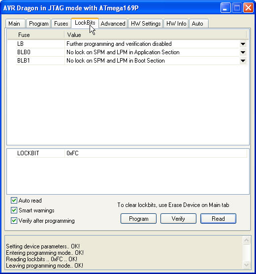
The original software from Honeywell cannot be read from the Flash,
because of the lockbit settings.
original_* is code from rfmsrc branch compiled without RFM12 support. It
is for valve "out of the box".

I am not have any changelog file, but you can see to SVN logs and major
changes is in this thread.
Jiri - thanks for Your advice regarding svn.

1. Can You guys please verify the following:
I thought, when the wheel is not turned, the 2 encoder signals should be
either 0 = or 1. Because the state between the two should only differ
during a small periode, when turning the wheel.

On my HR20 one signal changes as expected between 0 (position A) and 1
(position B). But the second signal is always = 1 no matter if the wheel
is in position A ob B. (it changes state between the 2 Positions).

Is my encoder defect ?


2. I only found something about the encoder in keyboard.c. But where is
the evaluation of the 2 encoder signals direction  phase ...?
@Richard G.:

Encoder have 4 states ....00-01-11-10-00.... (or back)
ROT1 signal have permanent pull-up. (value in schematic is wrong)
ROT2 use pull-up in AVR, but this pull-up is enabled only for reading
(save energy)

If you have only "1" on wire, encoder must be failed.

Direction code is in keyboard.c lines 69-81
1. encoder
YES I know about the 4 states and that rot2 is only enabled during
reading....BUT let's assume the following:

We have wheel position A, B, C and position A-B, B-C which is between A
and B (or B and C) when turning the wheel one step (always the same
dircetion). rot2e ... is what I would expect from rot2!

turning the wheel 1 step from A to B:
signal______A____________A-B____________B
rot1________0____________1______________1
rot2________1_0_____________1___________1
rot2e_______0_______________1___________1


turning the wheel 1 further step from B to C:
signal______B____________B-C____________C
rot1________1____________0______________0
rot2________1_______________0_________1_1
rot2e_______1_______________0___________0

So rot2 is late at position A and early in position C. The hr20 is still
dedecting the the turning of the wheel correct...BUT I am going to
simulate the encoder rot1/2 with the PLC I have set up in my house and
here it causes me troubles ....
Anyway I think the encoder is defect .... ?


2. Toolchain
A typical novice question  - I  know ;-) but I have installed AVR studio
SP3 and WinAVR20100110(GCC 4.3.3,avr-libc 1.6.7cvs).
I did not install avr-toolchain-installer-3.0.0.240(AVR-GCC: 4.4.3,
AVR-LIBC: 1.7.0) so far.
I would like to produce excatly the same binary and hex as you do. But I
still want to use AVR Studio 4 for loading and debugging together with
my AVR DRAGON....

a) What do I have to download/install ???

b) In studio I tried to use your makefile from ..rfmsrc\OpenHR20. But at
least I can't tell studio to pass the make parameters "RFM=-DRFM=0".
What do you suggest ?
add Info regarding 2. toolchain: These are the restriction for ext.
makefiles in studio4:
-The name of the elf file to debug must be projectname.elf
- To enable clean or rebuild, the clean target must be defined in the
makefile.
- The makefile must reside in the same directory as the output elf file.
- Compiling of single files will only work if this file is defined as a
target in the makefile.
@Richard G: Why do you need simulate wheel? If you want control walves
remotely, you can use serial connection (done in code), wireless
connection (done in code), or RJ485 (need HW mod and small SW mod)
Simulate wheel can make problem, it is not used only for temperature
setting.

If you want debug code in AVR studio, you need change you configuration
in config.h. Compile code in AVR studio (you have project file in
repository), start debug with dragon and enjoy. Where is problem?

------------------------

PS: do anybody any news about "Homeexpert HR20 Style" hardware from
Conrad?
Jiri: I have a homeexpert from amazon at home - so far PCB seems to be
the same. I will get my Dragon end of this week....

Encodersimulation: Thanks for your hints but I have parallel cabeling
(50 wires 24VDC/220VAC ;-) running through my house and PLC has no
RS485. It works already fine without SW-change on this one:
http://www.amazon.de/Heizk%C3%B6rperregler-Energiespar-Heizung-Thermostat-Boost/dp/B004AKB44M
But on hr20 I have to change the wheel task ...

________STUDIO&DEBUGGING_____WILL THIS WORK ?
I hoped that I could debug if I use your hr20.aps and tell studio to use
your makefile from ..\rfmsrc\OpenHR20\ with the following changes :
Line 137:
# Place -D or -U options here for C sources
HW_WINDOW_DETECTION=-DHW_WINDOW_DETECTION=0
RFM=-DRFM=0
#REV=-DREVISION=\\\"$(REV)\\\"

Line 269
#---------------- Programming Options (avrdude) ----------------
AVRDUDE_PROGRAMMER = dragon_jtag

________TOOLCHAIN___
- What is your toolchain ?
- Is it available for Windows Users ?
Richard G. wrote:> Jiri: I have a homeexpert from amazon at home - so far PCB seems to be> the same. I will get my Dragon end of this week....>
@Richard:
what does the display show during boot (after inserting the batteries)
before you have to enter the date?
Problem is that I want to know about this "HR20 style":
http://www.conrad.de/ce/de/product/615952/

@Richard G: Makefile in AVRstudio is used only for compile, not for
communication with AVR dude.
Hi all,

I wanted to ask who of you is running the daemon on which device?

AFAIK Jiri has an OpenWRT router and connected the master HW via serial
lines.

I have a AVM FritzBox 7270v3 and I'm using the FTDI FT232R USB-serial
converter.

The problem is that my FritzBox crashes after 1-8 hours of running the
daemon.php with php-cli, and I'm not sure why.

There might be several root causes:
1. Kernel is too old and FTDI driver also. Kernel version is 2.6.19.2
and cannot be updated, because AVM has closed-source drivers for DECT,
WLAN, phone etc.
1a USB driver part
1b FTDI driver part

2. php-cli with daemon.php is unstable. Although I've done some
debugging and tried some changes in daemon.php, it didn't get any
better. php-cli does not report any error when the FritzBox crashes and
reboots.


So I'm thinking about:
- trying the serial console of the FritzBox (no USB)
- trying a Prolific PL2303 serial converter
- rewriting daemon.php in plain C as a real daemon


Jiri, is there any documentation of the protocol between the master HW
and the daemon?

Greetings,
Marco
@Richard G: Makefile in AVRstudio is used only for compile, not for
communication with AVR dude.

I have 3 toolchains: - AVRStudio + WINAVR + AVRJTAG mkI(clone)
- linux AVR GCC + AVRDUDE + same AVRJTAG
- ECLIPSE + dgb + avarice + same AVRJTAG

You can try any of this, its your choice :-)
@Marco G: I am sorry I don't have any documentation about protocol
between master board and php script. Except source code. And frankly
spoken: daemon.php is worst part of OpenHR20 project. I wrote it without
concept only for debuging master-slave wireles communication. And
because it works, it still in project.
Problem with your fritzBox is probably RAM. I have hacked HW to 64MB of
RAM and it is "rock stable" independent to dirty code in daemon.php
Do you have swap? (you can use flash, it is almost not used). Old and
persistent problem of PHP are memory leaks.
jiri: I had both at home. Your Link HR20 has the same electronics like
the homeexpert
http://www.amazon.de/Homexpert-Honeywell-HR20-Style-programmierbarer-Heizk%C3%B6rperregler/dp/B003URRKP8

Sorry but now you confused the novice ... does it mean one can't use an
external makefile if one wants to debug with studio ???

Could you/someone please explain
"Makefile in AVRstudio is used only for compile, not for
communication with AVR dude."
Hi Jiri,
RAM shouldn't be the problem. I can see some MB still free in rrdstats,
and I have a 128 MB swapfile on USB storage, which is only up to 3% in
use. The FritzBox already has 64 MiB RAM.

My php is 5.3.5.

I'll try to find out the protocol from source code in the next few days
and then you can check if I got it right :)
@Richard G: where is problem with development environment? You have
HR20.aps project file. Open it in AVRstudio, press F7 for compilation.
and you have ELF binary + hex

DEBUG: Find Debug->Select platform - dragon and you can start debug
session

PROGRAM: Tools->Program AVR -> Connect - dragon ....
@Richard G: minimaly this
http://www.amazon.de/Heizk%C3%B6rperregler-Energiespar-Heizung-Thermostat-Boost/dp/B004AKB44M
can't be same HW as HR20. From first point of view, it have different
LCD (weekday symbols)

I have idea where is problem with wheel external control. Problem is in
pull-ups. My SW enable ROT2 pull up close to reading signal. Pull-up is
normaly disabled, because it increase consumption (60uA-150uA on "bad"
encoder position). But if you connect external wires, you increase
parasite capacitance and internal pull-up is not able to pull signal up
in time.
Solution is simple, use additional external permanent pull-up.

Makefile contain many choices, but you need only disable RFM extension.
Others are for test or special situations.
Jiri: This Valve attached is not HR20 Style, but works for me without
SW-Mod....

I still have not understood, why I should not be able to use the
..\rfmsrc\OpenHR20in\makefile from within studio4 including this
Modifications:
Line 137:
# Place -D or -U options here for C sources
HW_WINDOW_DETECTION=-DHW_WINDOW_DETECTION=0
RFM=-DRFM=0
#REV=-DREVISION=\\\"$(REV)\\\"

Line 269
#---------------- Programming Options (avrdude) ----------------
AVRDUDE_PROGRAMMER = dragon_jtag

Maybe I will understand it when I get my Dragon ...
you need only this:
RFM=-DRFM=0
all others can be default

you don't need makefile for programming

PS: your picture looks completly incomatible with OpenHR20
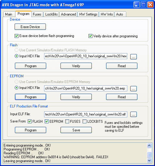
The novice was lion-hearted, Valve is running ... but....

I programmed the original_sww V1.0 hr20.elf File and the Verify of the
EEprom brings up this:
"warning EEprom Adr.14 is A0, should be A4"

Hints would be very welcome
Hi Richard,
the EESAVE fuse is set, so you cannot program the EEPROM correctly.

Clear it and program the EEPROM again, then it will be fine. Then set
the fuse again to preserve the EEPROM content during future updates.
Thanks for the very fast reply !!!!!!!!
The jpg from the last post was before programming ... after programming
the .elf the lockbit Tab loos different ...

My translation of your hint:
1 uncheck the EEsave fuse in the fuses tab
2 check the fuses checkbox in the programming tab
3 programm EEprom (or .elf file ???)
Right ?
nearly right ;)

step 1: uncheck EESAVE
step 1.1: program fuses on fuses tab
step 2: not necessary, that's only for reading from the device and
saving to an elf file
step 3: choose ELF and program it
Hi!

I just flashed version 1.0 with the hardware window detection. I think
this is the only way to really determine if a window is open or not, so
I much appreciate this new function. Thank you very much!

The hardware window detection uses the PE2 pin.
If I leave it open (not connected), rondostate shows "open".
If I connect it to VCC, it shows open.
If I connect it to Gnd, it detects a closed window.

I think it should be just the other way around, because if someone does
not want to use the hardware window detection or if you disconnect the
sensor, ist goes to open and won't heat any more.

Idea:
- Enable pullup
- Check if pin is high or low
- When high: Not connected or closed window
- When low: Open Window
- Disable pullup for power safe

Chris
Dear all !
a) What is the right way to change the Temp.Offset (room 23,0  / Valve
says 22,3). Do I have to change it here in eeprom.h or is there a
simpler way ?:
  /* 19 */  {295-TEMP_CAL_OFFSET,295-TEMP_CAL_OFFSET, 0,        255},
//!< value for 35C => 295 temperature calibration table
  /* 1a */  {340-295,340-295,      16,      255},   //!< value for 30C
=> 340 temperature calibration table
  /* 1b */  {397-340,397-340,      16,      255},   //!< value for 25C
=> 397 temperature calibration table
  /* 1c */  {472-397,472-397,      16,      255},   //!< value for 20C
=> 472 temperature calibration table
  /* 1d */  {549-472,549-472,      16,      255},   //!< value for 15C
=> 549 temperature calibration table
  /* 1e */  {614-549,614-549,      16,      255},   //!< value for 10C
=> 614 temperature calibration table
  /* 1f */  {675-614,675-614,      16,      255},   //!< value for 05C
=> 675 temperature calibration table

b) Please explain function of Temp.tollerance (set to 50) in
controller.c

c) I would like to implement a BOOST function I saw on the other valve:
If the user presses e.g. middle and right button the valve should open
to 100% for e.g. 5 Minutes (eeprom).
- Where is the best location to implement that ?
- Some hints hoe to implement that would be very very welcome ;-)
@Chris: You have almost same idea as is implemented in code. Only one
difference: "low" means closed window. Reason is magnetic window
contact. It is imposible buy inverse functionality.

@Richard:
a) you have correct space to do this, but table is inverted, you must
recalculate it.

b) config.temp_tolerance: Integrator is not updated everytime. It test
change direction and it is "lazy" around zero error +-
config.temp_tolerance

c) right place is menu.c & controller.c/CTL_update.
- menu.c you need update for event from long key press
- controller.c for change functionality
Thanks Jiri:
RE: Temp.Offset ... The temp. gap comes from the cold wall.
As this offset differs depending on outside temp I am thinking about one
simple variable I use as Offset for the user. Do You have a better idea
?
Hi Jiri,

I always used magnetic contacts for alarm alarm systems. They have 3
pins (com, no, nc) and switch a common pin between the other 2 pins. But
it seems they are not so widely used any more, neither reichelt nor
conrad has them...
However, it doesn't really matter because you can easily disable the
windows function.

@Richard: I think you can't fully compensate the influence of cold walls
or hot heaters, because they both change too much. The only way would be
to mount the sensor at a different place.
@Richard: yes, ADC_Convert_To_Degree(int16_t adc)
but please use config.temp_offset (it must be 8 bit only, but +- 1.28
eventualy +-12.8=multiplied by 10 degree can be enough)
8 Bit * 10 would be fine. But the old guy is not very firm in C. What
you mean with config. ... I thought about a Variable in EEPROM ... how
do I have to implement that ?
Offest_temp might differ betwenn some heaters. So SRAM would be fine
too. The oly disadvantages are, that it has to be set again after a
batttery change and during software development ... In any case, the
value must be adjustable by the user ...

1. What do you prefer ... and how do I have to implement that ?
2. Which menu should I use to let the user set the value ?
@Richard G: I prefer store it in EEPROM. Why?
- you need only add this into eeprom.h (config structure and
value,default,min,max table)
- mechanizm to change this value it already implemented in service menu
etc.
-except change in eeprom.h you need only use this value

Do you realy want it? It is only 0.7degree (precision of used NTC is
worst) nad it depend to air flow (external temperature)
Jiri: YES. Actual to measured temp. differs between 1,5 and 1,9 °C (even
more, if outside temp falls) in my rooms !
Change by Service-Menue is not comfortable enough. What about
menu_preset_temp4 ??

@adlerweb: I use this openhr20/rfmsrc/OpenHR20/Makefile with studio4 ...
must I check out your change ???
@adlerweb: it is not regresion. It depend to version of avr-size. I have
version "GNU size (GNU Binutils) 2.20.1.20100303" and it works on linux
fine. I must know it, because linux is my primary system and official
binaries for version 1.0 is compiled on linux.
Small warning: If you aren't experimentalist, please don't use SVN code
Revision > 294 ( > Feb 26 18:20:11 2011 UTC ).

I am trying to modify PI controller to allow use lower gain on loop.
Reason is improve stability in some situations ( versions <= 294 can
have oscillation around wanted value. note: normal mechanical "wax"
regulator have same problem in this situation )

But current code have "PI windup" problem. It can cause long delay after
temperature change. Current(= SVN rev 297) anti-windup protection (based
on detect valve saturation) isn't sufficient.
Jiri Dobry wrote:> b) config.temp_tolerance: Integrator is not updated everytime. It test> change direction and it is "lazy" around zero error +-> config.temp_tolerance
Valve setpoint=23,0 ValveTemp=23,4
It seems this difference(0,4°C) stays all the time / is not corected by
the controller ... is config.temp_tolerance causing this ??
Should I change #define EE_LAYOUT (0x10) to ???? if I add my Offest temp
to config_t ?
/* 29 */ int8_t  room_temp_offset;

/* 29 */  {18,         18,     -127,     +127},   //!< offset to
roomtemp 1=0,1°C

BTW: I always get this warnings:
../common/rtc.c: In function 'RTC_timer_set':
../common/rtc.c:575: warning: 'next' may be used uninitialized in this
function
../common/rtc.c: In function '__vector_4':
../common/rtc.c:678: warning: 'next' may be used uninitialized in this
function
@Richard G:
Your code looks OK, bud nin&max must be one-complement number (this
table is unsigned) {18,18,0,255}
In config_t you can use signed int8_t without problem.

Warning on rtc.c is correct, compiler is not able to see, that we don't
need init it. I can be fixed by "dummy" init, but it take space in flash
and situation on free space is almost critical.
@Jiri:
Thanks, but is     /* 29 */ int8_t  room_temp_offset;
correct or do I have to use uint8_t here as well ?

1. Should I change #define EE_LAYOUT (0x10) to ????

2. Controller Problem?     Valve setpoint=23,0 ValveTemp=23,4
It seems this difference(0,4°C) stays all the time / is not corrected by
the controller ... what could be the cause ??
Jiri:
I tried to calculate/understand the controller with I=0 and my
error=400=0,4°C

WHERE IS THE MISTAKE IN MY CALCULATION ?
error16  400

PP_Factor * abs(error16)  17600
.P_Factor <<8  3840
sum  21440

pi_term *= error16  8576000

pi_term >>= 8  33500
valve_center)*scalling_factor  14080
sum    47580

pi_term16 >>=8  186
@Richard G:
In config_t you can use signed int8_t without problem.
add 1. You can, but it is condition only on public code.
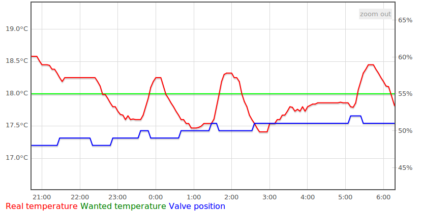
add 2. except temperature we need optimize motor movements. It is normal
if temperature is +-0.6 degree around wanted. See to my data from last
night. Most significant for compensate systematic offset is integration
part of controller. But it take many hours to find this value (gain of
this loop is small and must be small to prevent oscilations)
Jiri:
a) where in the controller is the part for reducing motor movements ?
(power consumption is not important to me, because HR20 is supplied by
PLC controlling its setpoint (by encoder simualtion;-)

b) still have not got the problem in my calculation:

pi_term = ((int32_t)config.PP_Factor * (int32_t)abs(error16));
17600=44*400

pi_term += (int32_t)((uint16_t)config.P_Factor <<8);
21440=17600+15*256=17600+3840

pi_term *= (int32_t)error16;
8576000=21440*400

pi_term >>= 8;
33500=8576000/256

pi_term += (int16_t)(config.valve_center)*scalling_factor;
47580=33500+ 55*356=33500+14080

pi_term16 >>=8; //= scalling_factor;
186=47580/256
@Richard G:
Now you don't have any problem on calculation. 4 degree error is outside
regulation range. Few lines later, result is limited to valve_max (80%)
and it fully open valve.
a) where in the controller is the part for reducing motor movements ?

b) I see - thanks ... so error16=0,4°C= 40 then ???

c) Is valve_min (30) the point where the heater sould stay cool ?

d) What do you suggest - where to start to reduce the error from 0,4 to
+-0,15°C. In your chart, one can see that temp over- AND undershoots the
setpoint. But in my case it stays above all the time (whole night).

Maybe P/PP is to small, to correct possible offsets for valve_min/center
points ?!
result is 58% but it ignore integration part like I_factor=0

c) valve_min/max are points where any change have not any effect on
water flow. In reality its for example min=42/max=60, but it depend from
valve to valve

d) +- 0.15 is outside reality. You can't increase PP/P, it will
oscillate because whole system have big "propagation delay". And it is
impossible without I part (old name for this is "zero compensation")
valve_center (VC) you need on point where value < CP cause cooling value
> CP heating on usual situations. This setting is not critical, it is
compensated by I part of controler. (note: latest code in SVN have litle
improved code but it have unwanted "windup"-see to
http://en.wikipedia.org/wiki/Integral_windup)
Jiri:
Thanks very much for the deep look inside the secrets ;-)

Is there a way to set/force/fix the valve manual to a certain position.
I would like to find out where the heater starts heating ??
Jiri: Thanks for the explanation !

1. So the aim is:
Just move valve if difference from controller is more than 0,75%
RIGHT?

2. Could you please add the feature request RoomOffset as mentioned in
my Email...

3. Yesterday I changed the controller back to 1.0. With 304 roomtemp.
continously increased (difference was already >1°C), but 304 controller
reacted just with small reductions (about 2-4% in 1,5 hours or so)

4. Do you change controller or valve factors from eeprom, when you do
your tests ... if so, what are the values ??
My valve settings are:
Min:50% (it opens above 57 so I set to 50 to make sure it is closing),
Center 65%, Max:90%
1. Exactly, right

2. No, sorry. It have 2 reasons. I can't improve regulation of
temperature, measured value is not and can't be equal to real
temperature. For real temperature, you need more than 6 sensors and
calculate average. Try it move one thermometer around a room, you will
see. Second reason is flash size, we want to save almost every byte,
flash is almost full.

3. try 306, its side efect of windup protection, 306 use another than
304. Not tested now.

4. I usually using default values.
Jiri: Rookie question ;-)

During development it would be nice to which SVN Revision e.g. 309 is
running on the valve.
- Why don't we have something like 1.1_309 displayed on the LCD during
startup ???
- is their a revision-variable that is automatically updatet somewhere ?
and Jiri: I still have not understood your PID-controller... could you
post just the formular using your variable names like

pi_therm = error16*P3 + error16*P + sumError*I ....

new_valve = valve_center + pi_therm*....
used fixed point aritmetic 3bytes-dot-1byte

pi_term = (
    ( error^3 ) * P3   // cubic
  + ( error * P )      // linear
  + ( sumError * I ) / 256 // integral
  + valve_center * 256 // basic zero compensation
)

result is new (valve position * 256) in %

after trim, it is fixed point 1byte-dot-1byte in %

follow rounding with hysteresis and we have new valve position

Almost standard PI controler, but with non-linear response.

-------------
"why only new_valve>valve" is wrong question, it is polarity detection
of valve change. For "plus" it must be "new_valve>valve"
I want to find protection to windup problem. This code was test and not
work what we want.
Jiri: perfect expplantion ;-) THX

Missing in makefile:
CFLAGS += $(TEMP_COMPENSATE_OPTION)

Rookie question ;-)
During development it would be nice to see which SVN Revision e.g. 309
is
running on the valve.
- Why don't we have something like 1.1_309 displayed on the LCD during
startup ???
- is their a revision-variable that is automatically updatet somewhere ?
Revision number you can see in config.h
And it is send by terminal on start.

Problem is how convert SVN revision string into number for C compiler.
In Linux it is not problem, on Win I don't have solution.
Jiri: Am I right ?
1 Every time wanted temp changes (in my case 3 times a day) the I part
(sumerror) is reset - but where in the code ?

2 P + P3 error correction just have an impact of 3-5% when temp. diff is
about 1°C.

3. I do not understand the code where sumerror is limited with 50*I.
What is the result of Limit in % ?

4. So just I part brings us to the right valve setting, but this takes
several hours ....

5. Result: Maybe I watched it wrong, but it looks like if wanted temp is
changed, valve starts close to center position and the heater starts
heating, even if roomtemp is already 1°C to high !!!!!!!!!!!!
1. It is true on version 1.0, not in current code

2. you can increase P_factor, but major problem is that you not have
final "sumError" and wrong valve_center. If you increase P factor, it
will increase response of valve to error, but it will probably oscilate

If you really  need to know what happen, please use converter from 3v3
to RS232 or usb and create log. Without log you know nothing and usualy
have obly bad feeling.

3. it is 50%

4. It is normal after restart or battery change. Where is problem on
normal continous functionality.

5. You made deductions, but you don't know facts. Make logs and you will
see.
Jiri: RS232 has been/ is on plan for this weekend ;-)

1 Rev.309 I-Part:
Allow integration = integration time set to 4 minmutes, if
error==0 OR sign of error changes OR direction of valve movement
changes...
a) ==> so this means, that if there is a constant error, the error is
added max 4 times (once a minute) to sumerror ?
b) The max impact on PI then is 4*error*I

2 Under which conditions would you change P3 and und when P factor
Richard G:
Correct, code using UNIX end of lines to save flash and communication
size. Please use terminal which is able accept it. I recommend putty and
set it.
PS: MS hyperterminal is piece of ..... except other problems it was many
years unfixed bug, when you use bar to shift window contend, it change
contend

!!!!!!!!!!!!!!!!!!!!!!!!!!!!!!!!!!!!!!!!!!!!!!!
NOTE: SVN rev 318 contain biggest change after more than year, it is not
fully tested now. If you want to have rock stable code, please use
release 1.0 (SVN rev 285)
!!!!!!!!!!!!!!!!!!!!!!!!!!!!!!!!!!!!!!!!!!!!!!!
Jiri; Here is the protokoll from last night. Params of my valve:
  /* 0a */  {52,         30,        0,      100},   //!< valve_min
  /* 0b */  {60,         45,        0,      100},   //!< valve_center
  /* 0c */  {90,         80,        0,      100},   //!< valve_max


- It took from 22:42 until 1:50 until I part starts.

- I part does not increase until 2:29, no impact on V so far
- next I increase 3:37, no impact on V
- next I increase 4:09, no impact on V
- next I increase 4:13, no impact on V
- next I increase 4:17, no impact on V

- 5:01 my encoder simulation is runnning and needs about 15s to reach
the previous S=23,0"C again.

1.??? I thought that it takes 10s after wheel stops before PID is
updated ???

- next I increase 5:05, no impact on V
...
- next I increase 6:49, 1% impact on V

Resumee:
2. It starts increasing V, neverthelsess room is 1,75°C higer then S
3. Impact of I param is week. It seems that sumerror is increasing to
slow and I param is to low.
4. V on LCD is 1% less than on COM
Richard G:

What is your P, P3, I factors ?
Why you change setting in code, you can use service menu or terminal
(commands G,S)

1) it take 10sec, because wait to final setting. It is mornal if human
use wheel, that it not have machine precision. You ca see it in
CTL_temp_change_inc

2) again, what is P, P3, I ?

3) normaly it my valve it take 12-24 hours to find sumerror (I impact).
It must be slow, you can try in rfmsrc/doc/PI_tuning what happen on big
gain. I hope that 318 is faster without impact to windup (do yyou know
what is it?)

4) com show wanted valve, LCD show truncated real position. In real
world, I want 29, com show 29, but real position after valve stop is
28.99 -> LCD show 28. Reason is allow see motor movements on LCD in real
time.
Jiri: PI params are standard, yes I understand windup, but 24 hours to
find error is to long, because setpoint is changed more often

- ad 1) This would help to prevent update during wheel action:
controller.c 150:
if (((PID_update_timeout == 0)
1
&&(PID_force_update==-1)
) ||(PID_force_update==0)) {

- How can we prevent 2 ?
no 24 hours is not too long, it persist after change setpoint

for remove delay, please change in CTL_temp_change_inc

PID_force_update = 10;

to =>

PID_force_update = 1;
Thanks Marco !

Thanks for the hints Jiri:
PID_force_update = 1; forces update
But we want prevent update during wheel move:
if (((PID_update_timeout == 0)
1
&&(PID_force_update==-1)
) ||(PID_force_update==0)) {

This prevents "normal" update (every 4 minutes) until 10s after wheel
stops !
Hi!
How do I find the "correct" values for minimum and maximum vent position
(0x0A, 0X0C)?
Maybe a feature to "live-control" the valve would be nice.

Chris
- set Max=Center= Min+1, wait until heater is cool
- increase all params +1 until hater starts getting warm
- set Min e.g. 5 lower and center 10-20 higer. leave max at 80
Jiri just did some redesign on that, but I think NO.
Calculation in controller.c works with center position. Only I part
(sumerror) can't increase when MIN/MAX are reached ...
This is why I set the center closer to MIN ...
Thanks Jiri, I saw that before, but there is no formula for the
simulation in the Excel sheet ??

BTW: Where do I find Karims latest Version of his openHR20Suite. I only
found Version 0.2.4.23954 posted on page 2 ??
@Richard,

the last released Version V 0.2.4.23954 of openHR20Suite can be found
here http://embdev.net/topic/118781#1157863, but I think, it will not be
completely data compatibel. It seemed to me, that no body was interested
in this program and I had to do a lot of other stuff, so I had not the
time and motivation to keep it uptodate. But since I am still interested
in this project, I need to look, wether I am able to compile and flash
the latest Version of OpenHR20 firmware an check, what has to be
modified in the Suite SW. May be I can take a look at it on next
weekend.
Hi Karim, I have this Version runnning since last weekend. Execpt the
difference in the EEProm names it seams to work. But once I had a jam on
COM - no more data transfer, which just could be released by using putty
to send some manual commands...

The only thing, that bothers me a bit is, that I had to install .NET35.
Usally nearly every PC has some .net version installed. Very often it is
2.x ...

Would it be possible to parse the appropriate eeprom.h. This way one
could only copy this file e.g. into the program dir and would be up to
date. The second thing is that one has to configure which #defines were
set ..
Since the program uses WPF technology, it requires .NET V>=3.0. If you
want to see a flash movie, you have to install the appropriate flash
player, same for Silverlight or here .NET. That is how it works and the
installation is only once required. The installed .NET framework
versions can be found here C:\WINDOWS\Microsoft.NET\Framework and
generally you have anyway several versions on your PC.

It would be possible to read the eeprom.h file but it has a very
processing unfriendly format, which is errorness. It would be better, to
have an xml file, which contains the required definitions and on
modifications in eeprom.h, everybody could edit the changes to this xml,
which will be loaded by the Suite. Different versions of the eeprom
data/HR20 firmware could be handled by this method as well. But I can't
promise to program that one of these days.
@Karim: Would be nice ! Put your tool into trunk !!!

@Jiri:
My experience with 319 controller in a 15m² room during some nights with
no persons in it and predifined Params (except MIN=52,CENTER=60):
1 I Part takes about 2 hours until reaction is seen on temp. Maybe I can
be increased ??
2 I think it is important to set the MIN value close to the real CLOSE
of the valve, beacuse this limits I part
3 I is still increasing/decreasing even if the temp gradient has already
changed (from falling to increasing or vice versa) ...
4 suggestion:
Why don't we stop increasing/decreasing sumerror, as soon as the
gradient of the real temp changes to the wanted direction ?
5 D part missing:
In my case, the Valve runs on accu with permanent charge of 5mA via data
connection.
I need something, that reacts when e.g. a person enters the room or a
heating source like a PC is started ... waht do xou suggest ?
6 I have no idea of what is the impact/aim of P3 - can you please
explain ?
7 Regarding simulation: I saw the .ods before, but there is no formula
for the simulation in the Excel sheet ?? Do you have something like that
... how are you doing it ?
8 Am I right ? On COM we don't see every move of valve, because of
integer value ? Why not put valve*10 to display and COM ?
1. I thing not, you can just create oscilations
2. problem is that MIN value float after every calibration. And you need
value below to insure close and prohibit unlimited heating
3. do you have better idea to protect to windup and allow integration if
valve still in position and you have permanent offset ?
4. If you want it, please use version 1.0. Problem is, that it increase
oscilations on some situations (in my case only in one room)
5. D is removed because usually we have only batteries, and it have
problem with transport delay (it take more than 20 minutes till you are
able to see effect when valve close)
6 regulation characteristic of valve is non linear with unknown
"center". If you use big P you will get oscilations. If you use low P,
you are not sufficient reaction if calculated "center" (I part) is too
far for real. Therefore you need compromise, small reaction for small
errors and big for big.
7. .ods contain simulation formulas, you can convert it into excel
8. COM show final position on every valve move start
add to 4) I was wrong. It is realy used on release 1.0. I remove it,
because it not solve windup completely. Normaly you have more heat
sources (ex: sun) and it can create any temperature profile independent
to valve. It is replaced by another idea, but it is compatible. I plan
to use longer temperature history than only previous.
ad4) but you agree, that a further increase after temp gradient changed
leads to a unnecessary high I part ?
ad6) what is the max P3 before oscillation starts, can it be increased
???
ad7) I used excel2010 to open it, but did not see any formula. You say
convert ?? How ?
ad8) I thought smallest move is 0,75%
4) right, but with side effect, it slow down integration if you have
small offset to wanted temperature (ex 0.5-1 degree).

7) what is in rows P-V ? If just number please send compliment to
Redmond and download OpenOffice

8) it move valve in 1% steps. You need hysteresis to inhibit move for ex
from 40 to 41% if result of controller calculation is 40.49 and 40.51
R325: e.g. Temp is to high: Some time after temp is sinking it stops
integrating = OK, but then sun shines into the room and temp is
increasing agein. In this case it should continue integrating - it seems
that credit was already=0 at this time ?!
controller line 315
    lastAbsError = absErr;
    last2AbsError = lastAbsError;
should'nt this be the other way round ?:
    last2AbsError = lastAbsError;
    lastAbsError = absErr;
Example:
D: d5 01.01.10 12:00:17 A V: 52 I: 2380 S: 1700 B: 2459 Is: 0000
D: d5 01.01.10 12:04:17 A V: 52 I: 2390 S: 1700 B: 2459 Is: 0000
D: d5 01.01.10 12:06:37 M V: 56 I: 2384 S: 2300 B: 2459 Is: 0000
D: d5 01.01.10 12:10:37 M V: 56 I: 2384 S: 2300 B: 2459 Is: fd60
D: d5 01.01.10 12:14:37 M V: 56 I: 2384 S: 2300 B: 2459 Is: fac0
D: d5 01.01.10 12:18:37 M V: 56 I: 2384 S: 2300 B: 2459 Is: f820
D: d5 01.01.10 12:22:37 M V: 56 I: 2382 S: 2300 B: 2459 Is: f820
D: d5 01.01.10 12:26:37 M V: 56 I: 2384 S: 2300 B: 2459 Is: f580
D: d5 01.01.10 12:30:37 M V: 56 I: 2384 S: 2300 B: 2459 Is: f2e0
D: d5 01.01.10 12:34:37 M V: 55 I: 2384 S: 2300 B: 2459 Is: f040
D: d5 01.01.10 12:38:37 M V: 55 I: 2384 S: 2300 B: 2459 Is: eda0
D: d5 01.01.10 12:42:37 M V: 55 I: 2384 S: 2300 B: 2459 Is: eb00
D: d5 01.01.10 12:46:37 M V: 55 I: 2384 S: 2300 B: 2459 Is: eb00
D: d5 01.01.10 12:50:37 M V: 55 I: 2384 S: 2300 B: 2459 Is: eb00
D: d5 01.01.10 12:54:37 M V: 55 I: 2384 S: 2300 B: 2459 Is: eb00
D: d5 01.01.10 12:58:37 M V: 55 I: 2384 S: 2300 B: 2459 Is: eb00
1
D: d5 01.01.10 13:02:37 M V: 55 I: 2390 S: 2300 B: 2459 Is: eb00
 I think latest here credit should be set to max_credit
D: d5 01.01.10 13:06:37 M V: 55 I: 2390 S: 2300 B: 2459 Is: eb00
D: d5 01.01.10 13:10:37 M V: 55 I: 2390 S: 2300 B: 2459 Is: eb00
D: d5 01.01.10 13:14:37 M V: 55 I: 2390 S: 2300 B: 2459 Is: eb00

e.g. something like:
if (((lastErrorSign != ((uint8_t)(error16>>8)&0x80))) || (error16==0)
1
||(absErr>last2AbsError))
{ //sign of last error16 != sign of current OR error16 == 0
Richard G:
Thanks for  last2AbsError=>lastAbsError order problem. Fixed.

But I can't set credit to max_credit on (absErr>last2AbsError)
condition. This is exactly condition which must be "pay" from credit.
Otherwise we will see windup again.
Prob is, that the error persists right now. Is stops about e000. The
influece of I&P is to low this way. Heater keeps on heating ... room is
getting hotter  ... with last2error > error it would only wind up if the
error is getting bigger and in this case we must do something about it
!?
Is 327 just the copy prob or did you have a new idea ;-)
on one valve since 2 day (since 321) I very often get E3 after flahing.
In this situations the valve head (sitting on the heater) is fully open
before installation.
If I set head valve manualy somewhere between open&close before
installation, the error is gone ... any idea ???

old questions:
ad6) what would be the max for P3 before oscillation will start ?
6a) why one doesnt use P^4 ^5 instead of p^3 ?
Hi!
I'm using v1.0.

I too have the E3 problem in one room. I swapped the hr20 (but not the
part which contains the blue wheel) without success. Now I swapped that
part too. Tomorrow we will see if that helped.

Next problem is in the morning when the system heats up with water
temperatures up to 80 celcius.
Wanted temperature is for example 16 celcius, but room temperature goes
up to 19 celcius because the vent does not close fast enough.

In other rooms, wanted temperature is set to 21 celcius, the room goes
up do 23-25 celcius.

If I change wanted temperature (even from 16 to 16,5 celcius) the vent
starts to close.
Idea: Whatever is being reset when doing this, it perhaps should be done
as soon real temperature crosses wanted temperature?


Other idea would be to add some kind of temperature prediction, so that
openhr20 monitors if temperature rises and how fast it rises, and then
calculate 30 minutes into the future to compensate inertia of the
radiator.

Chris
Chris:

If you have E3 problem on one valve, it probably have problem with
"smooth" move. Solution is simple, set faster motor movement. It is more
nosily, but safe. In version 1.0 its setting "14", change it in service
menu.

Where you have valve and where you measure temperature? I was use
controller same as in 1.0 over year, without problem.

Temperature prediction would be nice. Problem is that we don't know
"transfer function" for all many different valves and it is imposible
implement Laplace transform (flash is too small and space is almost
gone).

If anybody have any idea, please feel free to do it. It is GPL code :-)
Jiri I will think about it ... but my feeling is: It is better to accept
windup in situations where Error grows and just block integration when
error gets smaller ...

Do you have explanation for this E3 phenomenon ?
1
On one valve since 2 day (since 321) I always get E3 after flashing when reinstalling it.
2
In this situations the valve head (sitting on the heater) is fully open
3
before installation.
4
If I set head valve manualy somewhere between open&close before
Richard

windup is not acceptable, integrator value outside reality make slow
reaction of controler (hours to start heating). Too slow and resulting
error is bigger compare to "permanet error". Please accept that less
than 1 degree of error is nothing compare to measure precision
(+-2degree, try compare 2 identical valves)

Except this you must compare it after may hour of operation when it
stabilize.

Another way to solve it is reset integrator after any change like in 1.0
release. But it need bigger I_factor (rel 1.0 use another scale than
current SVN). Problem of this is oscilaton in some condition (real
example from my one room:  t<-15 degree outside make oscilation
+-1degree inside with 2 hours period. valve oscilate +- 5%)
Richard you have 0.37 degree difference ;-)
And it will be better after few changes of temperature, because you will
have integrator more close to reality.

Calibration:

"Ad 1" is delay before real real calibration start
"Ad 2" open till motor slow down hard end. "Slow down" on this end in
reality is almost impact.
"Ad 3" close till motor is not possible keep it on wanted speed and slow
down over threshold (force to continue is too big)

Result is motor range in pulses. You can see it in service menu or Txx
command (see to watch.c)

If measured volume of impulses is <100 or >1000 it create E3 error
Usual volume of pulses is around 500
THX:
1 but how come that ADJ 1 then sometimes stays longer in the display ??
2 that error disapppears, if head (part mounted on heater) is adjusted
between open and close before installing valve
Jiri: In my case E3 typical comes under the following 3 conditions:

1. If I set the haed (blue wheel) to fully open and mount the valve. E3
comes directly after ADJ_1. This sometimes also happens on other
heaters/valves and seems to be a software prob.
It can be cured by setting the head somewhere between fully open &
close...

2. It comes directly after calibration (after ADJ_3), when the valve
should move to its 1st position.

3. It comes during operation ...
1
I wanted to find out the cause for my E3:
So I exchanged the motorunit (not the PCB) and the mounting head (blue
wheel). E3 is still there.
1
Facts:
A. It looks like theese E3 only occure, when the valve wants to start.
B. It has nothing to to with "smooth move" of the motor unit, but maybe
with the PCB.
C. The force needed to move the valve on this heater seems to be higher.
D. I am running on accu. So VCC is only 2,4-2,6V
1
Questions/Conclusions:
1. Is there a timeout after motor_start that can leed to E3?
2. Is there something like a torque_limit that can leed to E3 on
startup?
3. Can we give the motor more torque (boost) during start up ?
4. which eeprom parameters (e.g. light eye) also can leed to this
problem, please explain ?
5. I found a lot of E3(CTL_ERR_MOTOR) in the source code. It would be
easier to determine what caused E3, when we sepearate E3 into different
errors like E3a, E3b,....
Richard G:
answers to Q:

1) yes, (motor.c line 241)

2) no, it not detect torque_limit. It detect stop or slow down.

3) yes, but it have compensation to battery voltage (motor.c line 253)

4)
- motor_pwm_min  - minimum PWM for motor
- motor_pwm_max  - maximum PWM for motor
- motor_end_detect_cal - define maximum time between two impulses to
detect end in % of motor_speed - calibration (motor.c line 237)
- motor_end_detect_run - same as previous, but for normal run
- motor_speed - time between 2 impulses - simple controller keep motor
in this speed
- motor_speed_ctl_gain - speed controller gain
- motor_pwm_max_step - speed controler max step on PWM
You can try motor_pwm_max=0xff
you can try change line 241
you can try higher motor_end_detect_cal (default is 130 - you can try
200, but "touch" on the end of range will be little bit strong)
you can speed up motor_speed (default is 168, you can try for ex 100)
You can in debug.h "#define DEBUG_PRINT_MOTOR 1" and see serial console
(recommended, but it is just numbers because speed on this line is
limited)

It is many choices. But I can't found where is problem because it works
more than year for me without problem.
Jiri THX for your hints !!!!!!!!!!!!!!!!!

I built in E31-E35: Usally it is this error:
1
if((MOTOR_calibration_step==0)&&
2
(MOTOR_PosMax<MOTOR_MIN_IMPULSES)){
3
MOTOR_calibration_step=-1;// calibration error
4
CTL_error|=CTL_ERR_MOTOR;
The causes are:
week accu about 2,45V, new head which leeds to more torque needed
1
I suggest following solution:
1. Change back motor speed
 /* 15 */  {184,       184,       10,      255},   //!< motor_speed

2. Change battery compensation to 2,7V
                MOTOR_pwm_set((int16_t)(((uint16_t)config.motor_pwm_max
* 256) / ((bat_average)/(2700/256))));

3. The cause for the longer adj_1 in the display could have something to
do with bat calculation ...
Anyway, do we have enough time to calculate the bat average after boot
to secure bat compensation before calibration starts ?? Sometimes I saw
wrong values over COM like 4V... It also seems to be part of the problem
...
Can we secure and validate bat calculation AND compensation
yes, because it is OK as long as battery is fine. I think the prob has
to be cured somewhere else ;-)

Just an example of wrong battery calc (accu has 2,4V):
#Connection opened @ COM1, 9600, 8N1, DTR:On, RTS:Off
>V
V:OpenHR20 (10*16+3).( 2*16+7) Mar 14 2011 20:21:46 101
>D
D: d5 01.01.10 12:13:56 A V: 52 I: 2524 S: 1700 B: 3969 Is: 0000 E:08 X
>D
D: d5 01.01.10 12:13:56 A V: 52 I: 2524 S: 1700 B: 3969 Is: 0000 E:08 X
_____________________________________________
V:OpenHR20 (10*16+3).( 2*16+7) Mar 14 2011 20:21:46 101
D: d5 01.01.10 12:00:17 A V: 80 I: 0000 S: 1700 B: 0000 Is: 0000
D: d5 01.01.10 12:04:17 A V: 52 I: 2530 S: 1700 B: 4207 Is: 0000 E:04
We have enough time to calculate the bat average after boot.
bat_average cant be > 0 till we have AVERAGE_LEN measures (adc.c line
92)
and calibration can't start (main.c line 295)
It must be something different. Are you sure that you don't have some
parasite source of power? Usually it is 5V powered JTAG or serial
converter.
It you have 5V powered serial, 5V come from RXD signal to CPU. Solution
is simple, add one diode (example 1N4148 or any) anode to RXD on CPU,
katode to serial convertor.
JTAG is connected, but board has no power ... Serial comes from a
MAX2232 ... I will check that ! But anyway can we validate the calculate
voltage to sensible limits like 1-3,5V
Jiri: As most times - you were right. Seial and JTAG influence voltage
calculation... BUT the situation stays confusing:

- I made 3 versions ... bat. compensation with 2,6/2,7/2,8V
- I flashed 2,6V = Revision 327,
- disconnected everything
- accu (2,45V) out, wait 10s, accu in
- mount on head (heater)
- AD1, E3, motor was quite slow when it tried to start

- I flashed 2,7V
- same procedure, E3, no acustical difference when it tried to start
- I flashed 2,8V
- same procedure, WORKS OK, motor faster

- I flashed back 2,6V
- same procedure, WORKS OK, motor as fast as at 2,8 ???????????
- I took accu out for abot 10min.
- AD1, E3, motor was quite slow when it tried to start  ???????

- I flashed back 2,8V
- same procedure, E3, no acustical difference when it tried to start
???????
- I took accu out for about 10min.
- same procedure, WORKS OK, motor faster ???????

during this test, most times I just flashed the Programm and not the
EEPROM (EEsave fuse is set).
- Are there any parameters stored in EEprom until calibration is done ?
- Are there any variables not initialised, that may stay in RAM ?
I am confused and frustrated now .. I need some fresh ideas .. pls help
- Maybe 1 pulse is to short that motor reaches sensible speed ... ?
- but waht are your suggestions regarding the confusing E3 situation
described in my post ?
Hi!

Replacing the electronic part or the mechanical part of the hr20 was no
solution for the e3 problem. I also changed batterys.
I'm now trying with lower and higher values for 14.

It only happens at one radiator, so I think it's moving to heavy.

Besides: It is the only rondostat which shows a voltage of 3,55V (or
above, the output is limited by 8 bit + offset of 1V because I'm using
my own systen to readout the serial data from the rondostats).
Hi Jiri,

I can confirm this:
I have no external voltage at my rondostat, only the two internal
batteries and I'm also reading too high voltages.
I do not provide any external power to the rondostates.

Richard, how old are your rondostates? I bought four new ones and used
only one of them, which then showed the E3 error. Then I started
replacing the rondostat, but always used the new ones... never tried one
of the older ones.
Maybe they changed something with the hardware?
1. Chris do you have the wrong voltage reading all the time ?
2. When does the error occure (after AD1 = ADJ2 ?)
In my case it sometimes is OK, but I did not find out the case for i so
far. It might really be a Prob of the PCB. Because as I wrote I tried to
exchange the motorunit, but the error stayed !
Got mine (I have 6)
http://www.amazon.de/gp/product/B003URRKP8/ref=ox_ya_os_product
from amazon last month ... did you find a fabrication date somewhere ?
3. I attached You a Version ehich has implemented 4 different errors for
E3 = E31-E34 which correspond with the different locations in the code,
where E3 comes from !
3. I attached You a Version which has implemented 4 different errors for
E3 = E31-E34 that correspond with the different locations in the code,
where E3 comes from ! All my changes in code are marked //jr
Most times I get E34.
It looks that we have problem with motor start you can try:

- change "#define MOTOR_IGNORE_IMPULSES 2" to bigger. It define number
of motor pulses ignored on start to control speed.

- change motor.c line "motor_timer = motor_max_time_for_impulse<<2;" to
multiply by more than 4. Ex "motor_timer =
motor_max_time_for_impulse<<3;" multiplies by 8

- enable "DEBUG_PRINT_MOTOR"

Richard G: battery voltage measurement is one of oldest part of code.
(more than 2 years) and I have not any problem with this. Please found
where is problem, it can be useful for others.
Ex "motor_timer = motor_max_time_for_impulse<<3;" I tried that some time
ago. It did not help.

Prob is wrong voltage and this PWM calc:
MOTOR_pwm_set (config.motor_pwm_max * 256) / ((bat_average)/(2800/256))
If valve thinks it has 4V: PWM=175, 2,4V: PWM=291(will lead to 255)

Is voltage calculated with the same adc like temp ? It must have
something to with the adc or something is wrong with pcb.
1. so we should not ignore more than 5 (MOTOR_IGNORE_IMPULSES ) pulses ~
0,5%... right ?
2. Can you pls quick explain the 6 states of task_ADC. Is noise
cancelation only done for temp (  case 3:
update_ring(BAT_RING_TYPE,ADC_Get_Bat_Voltage(ADCW)))
you can use bigger value for MOTOR_IGNORE_IMPULSES. It is only for motor
speed controller, motor will be stopped on wanted position independent
to this.

Tip for test: use config.motor_pwm_max=config.motor_pwm_min=0xff and see
whats happen

AD steps:
1) (start_task_ADC) not used, just start ADC
2) battery, not used
3) battery, prepare for temperature
4) first temperature for compare
5) temperature, used only when result is same as previous, or repeat 5)
I built it into watch.c.voltage is defenitly measured wrong on this
valve = same values as when connected to COM
D: d5 01.01.10 22:55:16 - V: 56 I: 2534 S: 2450 B: 3255 Is: 0000 E:04

Motor when error occures:
+ 0aeb ae
+ 0767 ae
+ 075f ae
+ 0764 ae
- 0a7f ae
 07db ae

AND of course no error when setting pwm_min=max
+ 029f fa
+ 05bb fa
+ 04c4 fa
+ 04aa fa
+ 04a0 fa
+ 049c fa
+ 04a0 fa
+ 049d fa
+ 0498 fa
...
+ 04b4 fa
+ 04b2 fa
+ 04b7 fa
+ 06d0 fa
- 054d fa
- 04ae fa
- 049c fa
- 04d3 fa
- 04f1 fa
- 0504 fa
- 0502 fa
- 0509 fa
- 0501 fa
- 050a fa
...
nice, it is definitely compensation to wrong battery voltage.
I remember correct that you have Dragon? If yes, try it manualy.
Without start SW: Set AD reference to VCC, input channel to BadGap
reference and start measure. Result will be number representing known
voltage (1.1 badgap) on unknown scale (VCC). Calculate is easy. You can
compare this value to VREF pin on MCU (ADMUX must be switched to "AVCC
with external capacitor at AREF pin")

But this make one idea. VREF is "AVCC with external capacitor at AREF
pin" If you have different (bigger capacity) on VCC, it can create
problem with charge this capacitance after AD switch on (normally it is
in power down state). You can try add one or more "dummy" measures
before real or use code like for thermometer.
I repeated accu out/in noe several times and sometimes V is OK.
Interesting is, that the wrong measurements also differ .... Offest is
0,5-1,5V. I did not find this phenomenon on another valve .. but I just
tried reboot 5 -10 times....
1. Jiri can you please integrate a voltage display into menu (middle
button)
2. Do You have any idea to diagnose this wrong measurement and display
an error ???
3. Of Courese we could always start with MAX_PWM and it would work ...
but this way the users wont find out that they might have a defect valve
...
same thinking, but error stays hidden this way...
@Jiri please enter voltage display at least with a #ifdef for me and the
novice software guys ;-) with middle button
@Chris: here is my "hack version" with voltage display on first watch
variable and , E31-34, 5 Ignore Pulses, motor_timeout*8
Battery voltage on LCD can be enabled on rev 330.
change #define MENU_SHOW_BATTERY 0
to #define MENU_SHOW_BATTERY 1

I am not able detect wrong battery measurement. How? We are not known
reason.
Reason for battery voltage compensation was external power.
For debug and somebody for normal functionality use 5V power. With this
power it works, but motor is too strong on start.
With "normal" batteries one reason is bigger noise on motor start. We
can remove it or create option for this.
@Jiri: It would be quite usefull, if one could choose, that the
parameter menue (middle button) and the watch menues do not return
automatically to main menue. This way one could watch a specific
parameter without warming up the valve (by pressing the buttons all the
time) ... and it would be a lot easier during testing or valve setup ...
I hope to confice you ;-)
means .. something more professional than my quick hack:
if (( kb_events & KB_EVENT_NONE_LONG ) && (menu_state<menu_home2 ||
menu_state>menu_home5))

BTW: A little prob i have not figured out in menue is:
if I set a manual temp and enter menu_home2..5 and press AUTO/MANU
button to leave this menue ... sometimes my manual set temp is back to
auto again and sometimes it stays on manu - I think this has nothing to
do with my change !!???
Jiri:
1. Regarding my prob with changing to AUTO TEMP from last post (As I am
simulating the wheel with PLC, I am always on manual)

Why do we change_mode in menue_homeX keyboard.c ~260 ? Is this the cause
why temp is set to AUTO when pressing AUTO in this menue (sometimes) ?
mistunderstandig?!: If I want to exit alternate menue by pressing AUTO,
the wanted temp should not change, also the Mode should not change ...
in my case from "23,0 MANU" to "17,0 AUTO"... in some other menues AUTO
is also for EXIT without SAVE ! This is also bad for testing, because
integrator start all over again ;-)

BTW: The more I look into it, the more I am fascinated from the work
sticking in this source code !!!
Hi Jiri and Richard,

I'm sorry but I do not have my jtag programmer at the moment so I can't
flash the rondostates right now.

I just connected a logic analyzer to tx of the rondostat to see the
serial output and I get this: "B: 4446". Real voltage is 2,88V...

At the other rondostates, they report 2,62V to 3,34V. The one which
shows 3,34V is aprox. at 2,8V too in reality.

Interesting: When I used a multimeter to meassure the voltage, I caused
a short circuit between vcc and ground, so the rondostat did a reset.
Back in my room, where my laptop shows all rondostates, it says 255
which is <=3,55V. And: The rondostat sowed e3 after the reset.
ups, the last line should be:
which is >=3,55V. And: The rondostat showed e3 after the reset.

Btw: This is one of the newer rondostats, it still has the foil on it
which protects the display against scratches...
Out of 4 rondostates, only one showed a voltage of 2,8V as expected.
The others showed something between 3,5 to 4,4 volts....
The one with 4,4V shows E3.
Chris: Are you sure that you don't have other power source than
batteries? (Ex: serial cable powered by 5V, JTAG, anything)

You can try code from SVN. It contain EXPERIMENTAL improvement on
battery measure.

PS: it is strange that you measure invalid battery value. This
functionality need only MCU and capacitor on VREF pin.
Chris an I measure the same symptoms... I have just one valve that
behaves like this. Chris, when wiil you programm new code ??

Jiri:
1 mistunderstandig?!: If I want to exit alternate menue by pressing
AUTO, the wanted temp should not change, also the Mode should not change
... in my case from "23,0 MANU" to "17,0 AUTO" (I am always on MANU
because of my wheel simulation;-) ... in some other menues AUTO is also
for EXIT without SAVE ! This is also bad for testing, because
integrator start all over again ;-)

BTW: The more I look into it, the more I am fascinated from the work
sticking in this source code !!!

2. What about putting integrator_credit on "D" line for COM ... at least
during our testings ??


