Hello,

I want to control a LED matrix on a FPGA to implement a simple version
of the game Space Invaders.
But I encounter a problem : my FPGA is limited to 160 logic elements but
my code needs 314.

I implemented the led matrix on an array (7 rows) of std_logic_vectors
(1 to 5). All worked fine when I operate on the rows but lots of logic
elements (mainly multiplexers and "and gates") arose when I access a
single element of the matrix (ex : when I have to switch on lights
corresponding to the shoot of the player).
The code is composed of 5 entities : 2 buttons to move the player, 1
button to shoot, 1 entity to display the led matrix (a multiplexer) and
1 pseudo random generator to generate the ennemies randomly.

Here is my question :
Are there any ways to optimize the number of logic elements ?
By changing the representation of the datas, changing the entities,...?

I attached my code. I am a beginner so I apologize for the common
mistakes.

Thanks in advance!
Greetings!
Which FPGA are u using?
The code looks good. But i will take a deeper view.
Nathex wrote:
> 5M160ZE64C4

This is a very small and old chip. Your Design is small too, but too big
for this Chip.

Your Design fits perfectly in even very small up-to-date Chips.
Your Design just uses 7% of the smallest Spartan7.

So ... i would change the Chip and use newer Tools too.
The problem is that this is a project and the chip is imposed...
So if you say that the code is already optimized, I think I will reduce
the matrix Led. Is it still possible to reduce the number of Logic
elements by any ways?
Your Component display uses most Logic. This is because you use modulo
operator. Modulo is implemented as a division which is not easy in
Hardware.

If you would use numbers in 2**n operations would be much easier in
hardware.

Why has mul_speed to be a multiple of 7?

You may use 8.
1 | signal counter : unsigned(5 downto 0):=(others => '0'); |
2 | begin
|
3 | |
4 | case counter(5 downto 3) is |
5 | when "000" => rows_out <= row_1; |
6 | when "001" => rows_out <= row_2; |
7 | when "010" => rows_out <= row_3; |
8 | when "011" => rows_out <= row_4; |
9 | when "100" => rows_out <= row_5; |
10 | when "101" => rows_out <= row_6; |
11 | when "110" => rows_out <= row_7; |
12 | when others => rows_out <= "00000"; |
13 | end case; |
So the last 3 Bits of counter will be the used to divide the speed, it
will be divided by 8.
Thank you !
This improvement removed +-50 logic elements.
I also reduced the matrix by 2 rows.
But 206 / 160 logic elements remain...

-I also had a question, I didn't catch very well the difference between
variables and signal, which signals could be used as variables in the
code and why?
In Hardware, there are no variables. But variables are a language
construct which allows you to use combinatorical logic inside a process.
but you never need variables because you allways can use combinatorical
signals insted. but variables make some things easy.
Attached files:
-

Capture.PNG
38 KB
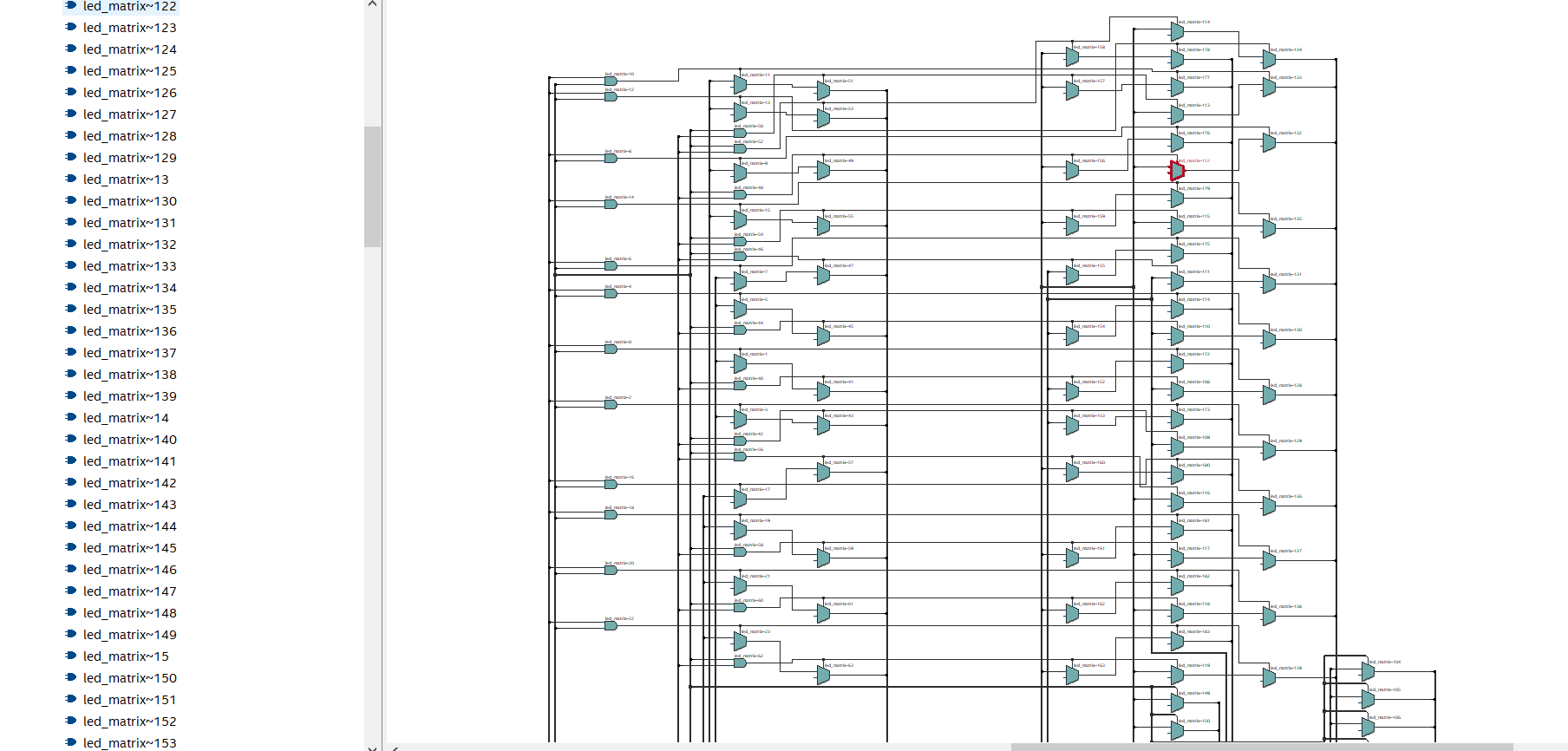
Ok thank you,

I would have a last question:
Do you know why are there so much multiplexers in the rtl viewer? The
matrix is now a 5x4 matrix, we can see in the picture that there are
more than 140 multiplexers. Do 5 multiplexers for each row would have
been enough to access each elements of the matrix?
You use some constructs in a strange way. in display.vhd the cols_out,
it is a buffer and gets shifted but ... it starts with all zero, shifts
right and fills with zero. so it never changes?! The synthesizer removes
the logic and ties cols static to zero.

What should button.vhd do? Do you really need an counter and an
statemachine to do that? should it debounce? you just implemented a
delay and the check if the input is still 1.

the lfsr can be written without variable.
Ok thank you I only have 41 logic elements. The main mistake lies in
button.vhdl
and don't know exactly why but I will try to figure out.

-I did a mistake in display.vhdl : I wanted to switch on and off
alternatively each row to display the matrix on the led matrix. The
initial value of the shifted vector should in fact be "00001".

-The button entity has 2 purposes : deboucing the signal and converting
the wide input from the button into a narrow pulse of 1 clk width. That
is why I needed a counter to not send twice a pulse corresponding for
the same press of the button.
Nathex wrote:
> The main mistake lies in button.vhdl
> and don't know exactly why but I will try to figure out.
Never ever use an async external signal without synchronizing it by the
means of 1..2 flipflops. After that you can use it in a FSM. For
sync'ing and debouncing the button input with edge detect see:

http://www.lothar-miller.de/s9y/archives/64-State-Machine-mit-asynchronem-Eingang.html

http://www.lothar-miller.de/s9y/categories/35-Einsynchronisieren

http://www.lothar-miller.de/s9y/categories/5-Entprellung

http://www.lothar-miller.de/s9y/categories/18-Flankenerkennung

Its German, try Google translate.


BTW:
In your code "input" is not needed in the sensitivity list. The process
only depends on the rising clock edge and therefore must be calculated
with each rising clock edge.
With other words: a change on input between two rising clock edges does
not affect the result of the process.
Please log in before posting. Registration is free and takes only a minute.
Existing account
Do you have a Google/GoogleMail account? No registration required!
Log in with Google account
Log in with Google account
No account? Register here.