Warning ... I'm a VHDL beginner , and am playing w. an Altera MAXII
EPM240 CPLD , using QuartusII V 13.0-SP1 - Linux
I'm trying to implement a PhaseFrequency Detector , and a 10MHZ to 1PPS
Divider.
The PFD seems fine , and so does the 1PPS divider (for now).
The 1-PPS divider is based on this entry
https://www.eevblog.com/forum/fpga/derived-clocks-best-practices/msg2909692/#msg2909692
And takes up 55 LE's out of the 240 , but then i got the "brilliant
idea" to add a 1PPS "Counter reset" , and after doing that the number of
LE's used dropped from 55 to 39 ????
How can that be ?
I have 3 examples on 3 lines.
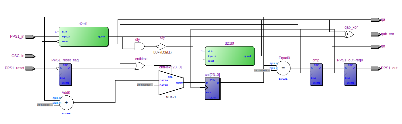
Ex1 is the original wo. reset - 55 LE
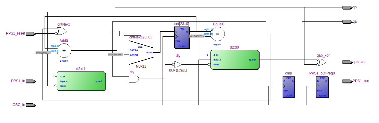
Ex2 is the one where i added a synchrounous reset (i hope) - 39 LE
Ex3 is the one where i added an async reset. - 38 LE (expected , no
reset sync FF)
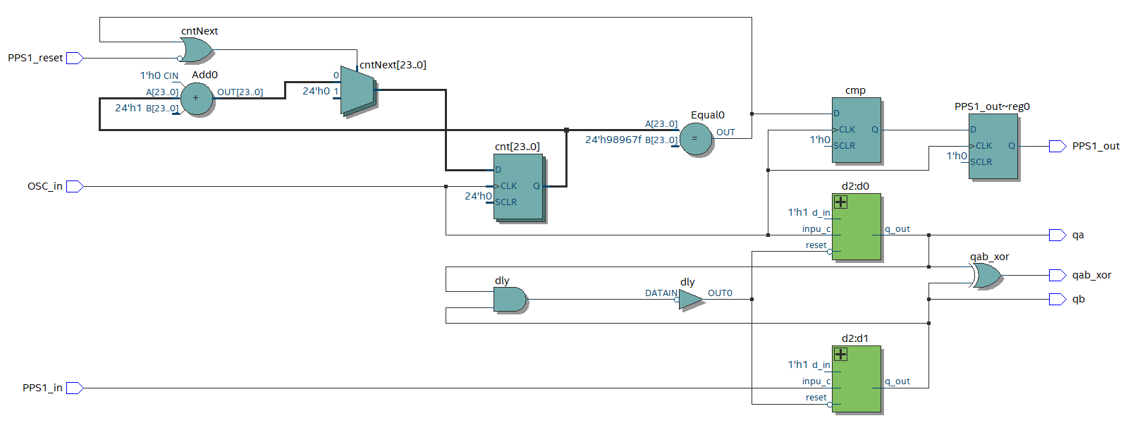
From dpd.vhd , enable one of the 3 lines
cntNext <= to_unsigned(0, Cnt_width) when cmpNext='1' else cnt+1; --
Ex1 - 55 LE used
--cntNext <= to_unsigned(0, Cnt_width) when (cmpNext='1' or
PPS1_reset_flag = '1') else cnt+1; -- Ex2 - 39 LE Used
--cntNext <= to_unsigned(0, Cnt_width) when (cmpNext='1' or PPS1_reset =
'0') else cnt+1; -- Ex3 - 38 LE Used
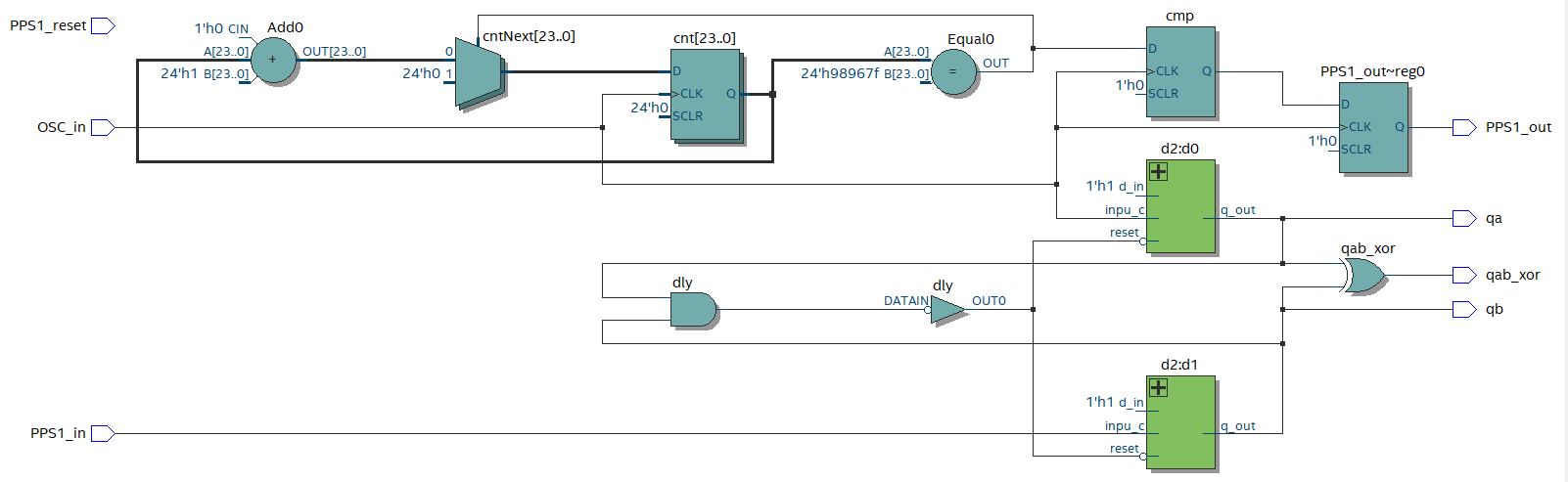
I have also attached the RTL's for all 3 examples.
How come a "simpler / without counter reset" uses 55 LE's , and a more
complex w. synch reset just uses 39 ?.
Have i messed with the functionality or ?
I have not tried it in real HW yet.
And (blush...) I can't write a TB yet , I promise i will learn.
Any hints are welcome
/Bingo
gustl FPGANotfallseelsorge wrote:> You have an active low reset but compare with '1'.
I negate the PPS1_reset on input to compensate for that (treat
PPS_reset_flag as active high).
The CPLD just have weak pullup's , no pulldown's . So an active low
reset was desired , in combination w. the pullup.
PPS1_reset_flag <= not PPS1_reset when rising_edge(OSC_in); -- Invert
PPS1_reset as it is Active low (weak pullup in cpld)
And in Ex3 , i do compare to '0' as i read direct from PPS_reset
/Bingo
Gustl, der Echte! wrote:> PPS1_reset_flag is not used.
Thank you for the comment
It is in Ex2 "just commented out" , in the current vhdl examlple.
And that version uses 39 LE , vs 55 LE for Ex1.
Hence my question , why does the more complex Ex2 use less LE's than the
simpler Ex1.
OK.

I wrote a little testbench and formatted your code.

Also:

PPS1_reset_flag <= not PPS1_reset when rising_edge(OSC_in);

This makes the PPS1_reset_flag  a clock synchronous signal.

So we have:

No reset:
cntNext <= to_unsigned(0, Cnt_width) when cmpNext='1' else cnt+1;
45 LE
28 Registers

Synchronous Reset:
cntNext <= to_unsigned(0, Cnt_width) when cmpNext='1' or PPS1_reset_flag
= '1' else cnt+1;
39 LE
29 Registers

Asynchronous Reset:
cntNext <= to_unsigned(0, Cnt_width) when cmpNext='1' or PPS1_reset =
'0' else cnt+1;
38 LE
28 Registers

So ... the differences are minor. I don't know why the footprint of the
design changes that much.
Gustl, der Echte! wrote:> OK.>> I wrote a little testbench and formatted your code.>
Thank you for your kindness.
> Also:>> PPS1_reset_flag <= not PPS1_reset when rising_edge(OSC_in);>
Thank you for verifying.
> This makes the PPS1_reset_flag a clock synchronous signal.
Thank you for verifying
> So ... the differences are minor. I don't know why the footprint of the> design changes that much.
Me neither.
I was worried , that i had overseen something when adding the sync
reset.
And it is strange to me , that making it more complex , reduces the
number of LE's ???
I will read up on TestBench usage , and try the TB you have made.
Thank you for taking your time to help out a beginner.
Once i have learned how to use the TB , i might want to "widen the
PPS1_out" , so it's not just 1 cycle (100ns) , but maybe 10/20 cycles
wide (1ms).
I'm sweating already .... I come from C programming , and this HDL stuff
flow is so different.
PS:
What version of Quartus did you use ?
Grüsse von Dänemark
/Bingo
Karsten F. wrote:> I was worried , that i had overseen something when adding the sync> reset.
No, all correct.
Karsten F. wrote:> And it is strange to me , that making it more complex , reduces the> number of LE's ???
Jap, but there may be many optimizations which we don't see.
Karsten F. wrote:> I will read up on TestBench usage , and try the TB you have made.
That would be great. The flow should be:
Write code, simulate till it simulates without errors, go to hardware.
I recommend the free version of Modelsim
https://www.intel.de/content/www/de/de/software/programmable/quartus-prime/model-sim.html
But with this 1 PPs you have to simulate a log timespan. Can be done,
just think how long you have to simulate. Otherwise you won't see
anything because the first transition happens after a long time.
Karsten F. wrote:> Thank you for taking your time to help out a beginner.
No problem, that's why i am here (-.
Karsten F. wrote:> Once i have learned how to use the TB , i might want to "widen the> PPS1_out" , so it's not just 1 cycle (100ns) , but maybe 10/20 cycles> wide (1ms).
Not shure how to understand 10/20. 10 or 20 cycles?
So i recommend not to use
a <= b when rising_edge(CLOCK);
yes it works, but for me code is mor readable/understandable when all
clocked action happend in one or more clocked processes. They can be
written as:
Without reset with wait statement:
1
processbegin
2
waituntilrising_edge(CLOCK);
3
a<=b+c;
4
ifd='1'then
5
e<=f;
6
else
7
e<=g;
8
endif;
9
endprocess;
Without reset with if rising_edge() statement.
1
process(CLOCK)begin
2
ifrising_edge(CLOCK)then;
3
a<=b+c;
4
ifd='1'then
5
e<=f;
6
else
7
e<=g;
8
endif;
9
endif;
10
endprocess;
With asynchronous reset with if rising_edge() statement.
1
process(CLOCK,RESET)begin
2
ifRESET='1'then
3
a<=(others=>'0');
4
e<='0';
5
elsifrising_edge(CLOCK)then;
6
a<=b+c;
7
ifd='1'then
8
e<=f;
9
else
10
e<=g;
11
endif;
12
endif;
13
endprocess;
With synchronous reset with if rising_edge() statement.
cnt<=cnt+1;-- counts up till 2**Cnt_width-1 and overflows back to zero.
11
endif;
12
endprocess;
13
14
output_pulse<='1'whencnt<20;-- 20 clock wird pulse, values (0 ... 19)
Karsten F. wrote:> I'm sweating already .... I come from C programming , and this HDL stuff> flow is so different.
Yes it is. It describes hardware and is not a program. Try not to think
in C.
Karsten F. wrote:> What version of Quartus did you use ?
The latest free version or so. Quartus Prime 20.1.1
https://fpgasoftware.intel.com/?edition=lite .
Be carefull, if you use an old CPLD, it may not be supported by the
newer Quartus versions.
Greetings from bavaria!
PS
Syntax highlightning is broken in the english section of the forum.
Thank you for getting back to me again

Right now i'm "figthing" modelsim linux
And have just gotten it to work on my Linux Mint 17 (Running as a
VirtulBox VM)
https://gist.github.com/PrieureDeSion/e2c0945cc78006b00d4206846bdb7657

Will read the above later.

Ps. Why did you recomend another modelsim , isn't the one in Quartus ok
?

Pps: I have to stay on 13.01-sp1 , as i also have a few EPM7K & EPM3K
CPLD's , 13.01 is the latest for those.

/Bingo
Karsten F. wrote:> Right now i'm "figthing" modelsim linux
If you have questions, ask.
Karsten F. wrote:> Ps. Why did you recomend another modelsim , isn't the one in Quartus ok> ?
It is OK too. Stay with that it it works for you.
Karsten F. wrote:> Pps: I have to stay on 13.01-sp1 , as i also have a few EPM7K & EPM3K> CPLD's , 13.01 is the latest for those.
Fine too.
Well in order to start modelsim from Quartus i also had to add the new
Freetype lib to the quartus environment file - (fixing i vsim wasn't
enough)
***** SNIP
If you want to launch modelsim from Quartus, you have to edit
quartus/adm/qenv.sh in the following way:
find the line export
LD_LIBRARY_PATH=$QUARTUS_BINDIR:$LD_LIBRARY_PATH
prepend it with the path to a folder containing libfreetype 32-bit
shared objects. So if you followed the instructions above, it should
look like this: export
LD_LIBRARY_PATH=/opt/modelsim_ase/lib32:$QUARTUS_BINDIR:$LD_LIBRARY_PATH
***** SNIP
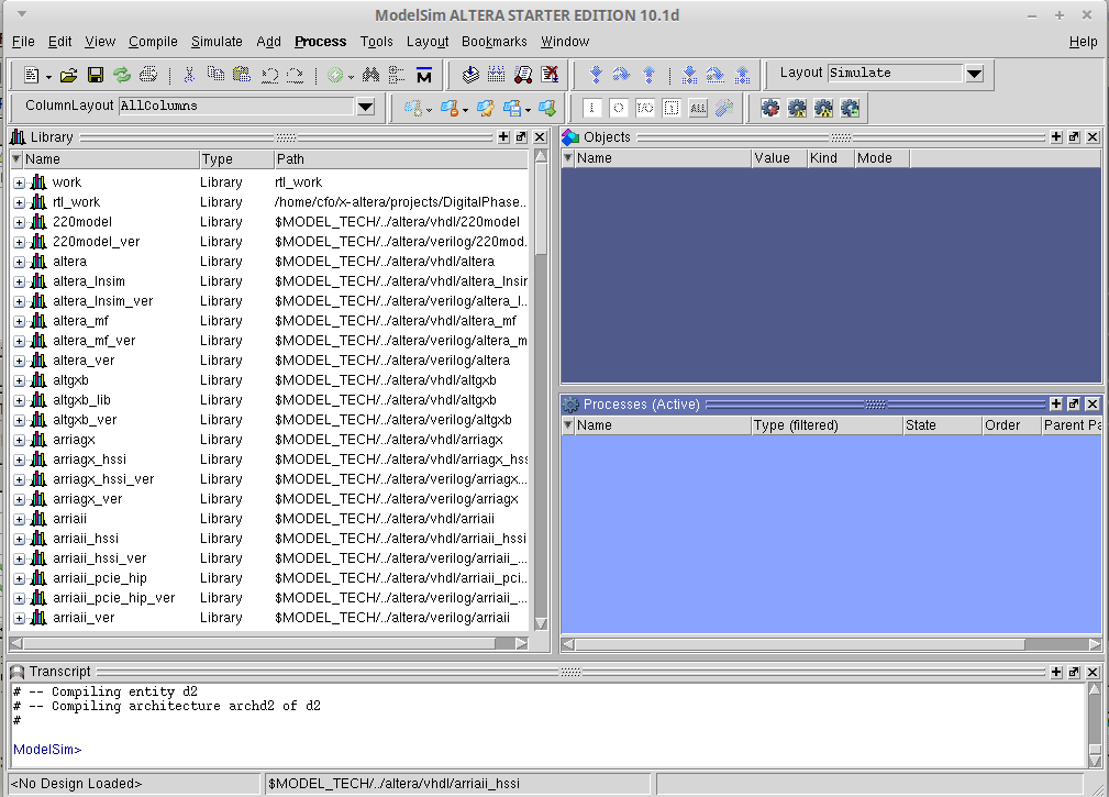
Now i see this (attached) when i do a Tools -> Run Simulation -> RTL Sim
Now to find out how i get it to see your fine TB file ???
And do something usefull in modelsim
/Bingo
It is quite unelegant , that one cant edit your posts after 60min ...
Well ..
I fumbled around , and "by luck" i got something to work (don't think i
can reproduce it ...)
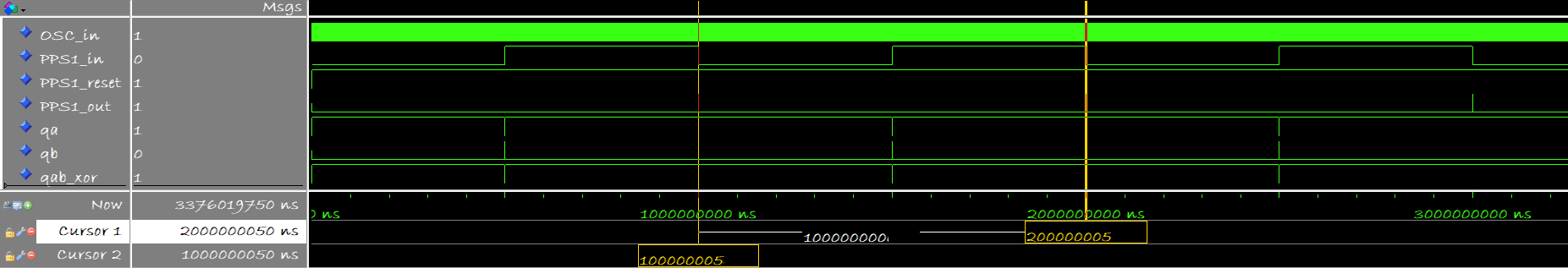
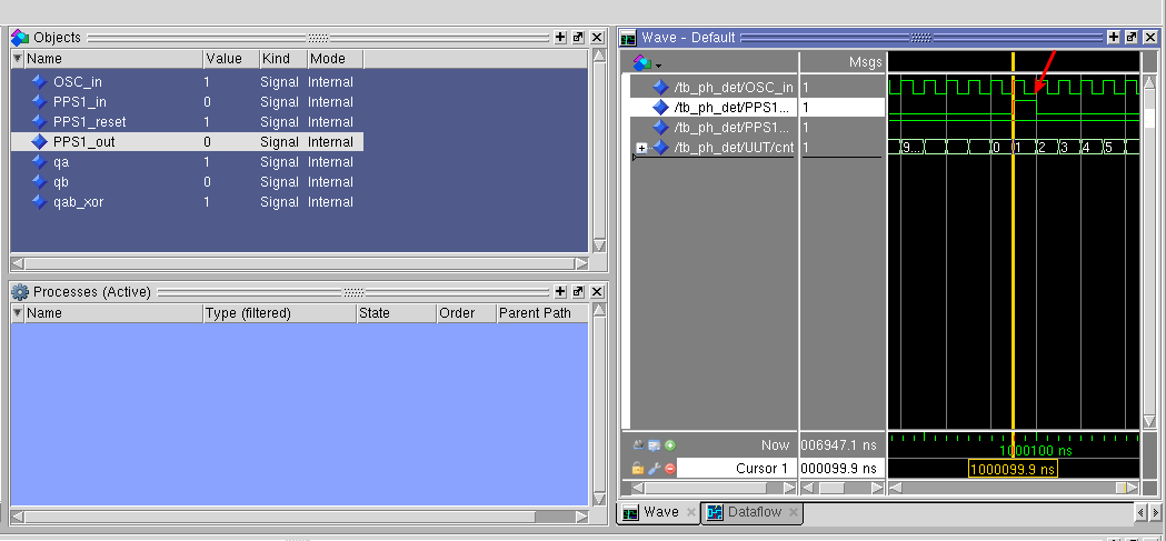
I got a PPS1 pulse in simulation
The time isnt spot on , ad i clicked a few times before i realized i
needed to set up a clock on the OSC_in.
I would have thought the TB did that ....
Well it seems to work , and make a pulse on the 9.999.999 to 10.000.000
transition.
So something is right here.
@Gustl - Thank you for taking your time to help out a beginner.
Maybe next weekend i'll get time po put it in real HW.
And i still have a lot of TB reading to do.
/Bingo
Karsten F. wrote:> I fumbled around , and "by luck" i got something to work (don't think i> can reproduce it ...)
Maybe you have luck again^^
Karsten F. wrote:> needed to set up a clock on the OSC_in.> I would have thought the TB did that ....
Yes, the testbench does that.
You have to simulate the testbench which includes/instantiates your unit
under test (= hardware toplevel).
When you klick start simulate in the top menu, select work and inside
work your testbench.
work.tb_ph_det
Karsten F. wrote:> Maybe next weekend i'll get time po put it in real HW.>> And i still have a lot of TB reading to do.
Good Luck!
>cnt<=cnt+1;-- counts up till 2**Cnt_width-1 and overflows back
12
>tozero.
13
>endif;
14
>endprocess;
15
>
16
>output_pulse<='1'whencnt<20;-- 20 clock wird pulse, values (0 ...
17
>19)
>

I reread this thread , to see if i missed something. And I DID !!
I totally missed the above suggestion to make my 1PPS signal 20
OSC-Clocks wide.

This is an elegant way to solve that , and i will try it asap.
Thank you for suggesting that.

/Bingo
Karsten F. wrote:> I totally missed the above suggestion to make my 1PPS signal 20> OSC-Clocks wide.> This is an elegant way to solve that
Although the output signal may have spikes or glitches at each rising
clock edge due to the combinatorial behaviour of the comparator
connected to the output.
I would do it this way:
1
signalcnt:integerrange0to9999999:=0;
2
begin
3
processbegin
4
waituntilrising_edge(CLOCK);
5
6
ifRESET='1'orcnt=9999999then
7
cnt<=0;
8
output_pulse<='1';
9
else
10
cnt<=cnt+1;
11
endif;
12
13
ifcnt=19then
14
output_pulse<='0';
15
endif;
16
endprocess;
Karsten F. wrote:> want to "widen the PPS1_out" , so it's not just 1 cycle (100ns) ,> but maybe 10/20 cycles wide (1ms).
1: You are aware that 10*100ns is just 1µs?
2: Usually synchronous design on FPGA work with clock enables which are
active just 1 clock cycle. So at 10MHz clock frequency the
one_second_clock_enable (your PPS1_out) is active only 100ns, then it is
inactive for the remaining 999999900ns.
And this one_second_clock_enable can be used in every part of the
design, that is clocked by the same 10MHz clock.
Gustl, der Echte! wrote:> So i recommend not to use> a <= b when rising_edge(CLOCK);
I recommend to read the synthesizers user manual. In it one can find
that small part of the whole big VHDL which the synthesizer ist able to
translate to hardware.
And in it there may be the solution to the original question: maybe the
synthesizer is able to generate smaller footprint by using "additional"
hardware.
Karsten F. wrote:> d2.vhd
Usually it is not a good idea to describe such fundamental hardware like
a D-FF on your own. Let the synthesizer do this. He has optimal
solutions for such components.
And never ever mix and muddle up async and sync resets in the very same
design. It will lead to strange effects like that changes of ressources
you have here...
Thank you Lothar

I will try your routine above.
I guess Gustl (der Echte) , was trying to go along with what i wrote
here.

The 1-PPS divider is based on this entry
https://www.eevblog.com/forum/fpga/derived-clocks-best-practices/msg2909692/#msg2909692
And was coding (helping me) along the lines that was suggested there.
He even suggested some procedures too (thanx)

Im using an Altera MAXII CPLD , and it doesn't have the "goodies" a FPGA
has.
I might not even be able to utilize them , if it had ...

Despite the beginner guidelines in the eevblog post, i will try to do a
procedure based attempt. And hope i don't mess up with clock and
metastability.

I'm just a hobbyist, picking up VHDL where i left off , at a 10 lesson
webcourse 4 years ago.

Should i also keep away from Altera DFF primitives , and let Quartus
decide it all ?
The only thing i have to keep is the short delay on the FF's resets,
else if there will be a deadzone when phase is equal, and reset is
immediate (so i read).

Thank you for your inouts and suggestions , much appreciated.

Edit:
Thank you for the us vs ms tip, missed that one (dooh...)
So i guess i'll have to use 10000 for 1ms@10MHz.
My scope would have caught it, but i ought to have seen that one.

/Bingo
Karsten F. wrote:> Should i also keep away from Altera DFF primitives , and let Quartus> decide it all ?
Yes, just write what you want and check afterwards the ressource report
for an unmatching number of flipflops.
When you have a counter 0 to 10000 you need 14 FF and so if the design
uses 20 then the synthesizer didn't understand your VHDL description.
Karsten F. wrote:> The only thing i have to keep is the short delay on the FF's resets
Sounds like someone didn't get the trick.
> else if there will be a deadzone when phase is equal, and reset is> immediate
This is the well known common "problem" with async resets. So usually
you have to sync the reset to the system clock to make sure it doesn't
go inactive at or within some ps around the clock edge.
> (so i read).
The only reliable source to read such things is the data sheet... 😉
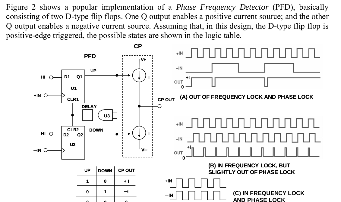
@Lothar

The Phase Frequency Detector is described here (Dead zone), and explains
why the delay is needed (for the next analog stage).

https://www.electronics-notes.com/articles/radio/pll-phase-locked-loop/phase-detector-digital-analogue-mixer.php


Even more in detail here pg2.
https://www.jmest.org/wp-content/uploads/JMESTN42351668.pdf

I tried to introduce a "Single Gate" delay in the design, with the dly
gate.

I can do a Flip-Flop in vhdl , but have no idea how to "reset it" with
the AND , if i don't use "primitives".

Any hints would be welcome

Edit:
After grumbling a little ...
Is that just an async reset meaning ..
IF Q1 = '1' and Q2 = '1'
  Q1 <= '0'
  Q2 <= '0'


Would the above generate a "FF" reset ?

How do i set the FF 'D1' to always '1'

/Bingo
Karsten F. wrote:> The Phase Frequency Detector is described here (Dead zone), and explains> why the delay is needed (for the next analog stage).
Yes, as I said: a deeply asynchronous design with a bunch of clocks. Its
not easy to get such things running properly on integrated hardware like
CPLD or FPGA. Those devices are not designed for logic like that.
Karsten F. wrote:> I can do a Flip-Flop in vhdl , but have no idea how to "reset it" with> the AND , if i don't use "primitives".
What can be seen in that screenshot schematic looks like that::
1
Q1<='0'whenrstd4='1'else'1'whenrising_edge(pIN);
2
Q2<='0'whenrstd4='1'else'1'whenrising_edge(nIN);
3
U3<='1'whenQ1='1'andQ2='1'else'0';
4
rstd1<=U3;-- inverter chain for delay
5
rstd2<=rstd1;
6
rstd3<=rstd2;
7
rstd4<=rstd3;
> I tried to introduce a "Single Gate" delay in the design, with the dly> gate.
You may have to do some tricks with such things like "keep" attributes.
Here I use it to create a chain of inverters to get some delay for the
ring oscillator:
http://www.lothar-miller.de/s9y/categories/29-Ringoszillator
But by far the most easy way would be to define an output pin for the U3
along with a input pin for the reset signal and add a RC delay between
them outside the CPLD... ;-)
Then the code looks like that:
Karsten F. wrote:> I use the keep for the dly gate i Quartus
Add some more, as 1 logic level is just something in the lower xxx ps
range.
> seems to work there too.
Check out the RTL schematic and the used ressources.