This is the new Thread about the OpenHR20 Firmware from
http://openhr20.sourceforge.net .

For generic Questions about the HR20, please look&ask in
Beitrag "Honeywell Rondostat HR20E per AVR steuern und konfigurieren"
Please write in English, thanks!
Guest
#1070711
SVN revision 100
    - improve motor control
    - check EEPROM layout on startup

From this version EEPROM layout is fixed. This mean that you can enable
"preserve EEPROM" fuse and your setting can be saved.

Change EEPROM layout case is tested on code. You will see "EEPr" on LCD
after restart, startup is blocked. With empty EEPROM you will see same
message.

*I don't know any missing functionality or bug at this moment.*

Permanet problem is missing documentation generated from sources. We
need it to document "magic indexes" on setting (Gxx and Sxxxx commands)
or watches (Txx command)

Changelog:
http://openhr20.svn.sourceforge.net/viewvc/openhr20/trunk/source/changes.txt
Guest
#1070927
Known problem for Rev100:
After change of PID constants you must change wanted temperature.
Problem is teoretical internal value overload. I never saw this problem,
but I found it on code review.
Guest
#1071577
SVN revision 101
    - optimizations
    - overload check in pid.c
    - change default setting for PID
Guest
#1071733
SVN revision 103
    - motor stop threshold for calibration / runtime can be different

EEPROM layout is changed, you can't preserve old contend.
@jdobry:
very busy weekend! gonna try your latest release tomorrow when i have a
JTAG-adapter again.
gonna give you feedback about how the firmware works.
will try to get familiar with the general firmware architecture then,
for example questions like "how can i issue a task evry sixty seconds"
which shall be the RFM's staus broadcast in sooner future...
so long!
Guest
#1071847
@ Mario Fischer:

execute task every second:
add it into "if (task & TASK_RTC)" section on main.c

execute it every 60 second have many choices
- use own counter inside "if (task & TASK_RTC)" (worst)
- same section as before, but inside new "if (minute)" condition
(better)
- same section, add condition "if (RTC_GetSecond() ==
config.network_addreess)" (best)

For interrupt from RFM you must add code inside "ISR (TIMER0_OVF_vect)"
and set "task |=TASK_RFM12" inside. Make code inside interrupt small as
is possible and move real functionality inside main.c "if (task &
TASK_RFM12) task&=~TASK_RFM12; ....."

f you have some code sniplets, please contact me by email. It have big
priority for me at this moment.
Hi Jdobri!
(what is your first name? I dont know if "Hi Jdobri" is correct ;)

ok, ive downloaded the OpenHR20-rev 103 and started to play with it...
I will try to integrate a RFM status sender for first approach.
I can say now, i will have to make changes in several files. For example
main.c in
  if (task & TASK_RTC) { ... if (RTC_GetSecond() == g_RFM_devaddr) ...
and so on.
I would try to encapsulate all RFM-stuff  in #ifdef RFM-blocks, so a
project-fork wouldnt be neccesary.
But im not sure if i can guarantee that it will be possible to
distinguish RFM and notRFM-code clearly in all future.
So, what do you want to do?
Can you give me an SVN-Account for the project? Im sure you will be
anoyed very soon if i start to mail you my code all the time...
So, tell me your plans!
Greets from Munich,
Mario

PS: First Request: I'd like to have the global variable uint8_t
g_RFM_devaddr to be adjustable by menu (1-254, others reserved for
broadcast or future usage) and storable in EEPROM.  Since youre master
of the menue it shouldnt be too difficult? ;)
Guest
#1072116
Plan is keep latest STABLE version in main trunk and create branch for
next development. By this way we can made anything include crazy ideas.

You don't need change anything on menu. Simple add line into eeprom.h
structure config_t and line into ee_config array. Don't forget change
eeprom layout map version to something for development (exaple #define
EE_LAYOUT (0xd0) ).
You can read it by config.g_RFM_devaddr and change it by service menu
(long press all buttons -select configuration press PROG change value
and press PROG)
Question about the Config-Menue:

Did i get this right?
I can edit the Variables in eeprom.h via:
1. Pushing [AUTOMANU + TEMPSUNMOON + PROG] for 3 seconds.
2. Then display shows XX:YY, ourbar shows all bars, XX blinks
3. with the scroller i select variable number XX, then i push [PROG],
then YY blinks and i can set XX's value (within the range given in
eeprom.h).

now its getting unclear: it looks like if i push [PROG] i'm back in
selecting a XX again. is the other value now stored? or how can i cancel
it (i guess via AUTOMANU] )? and what's happening if i push
[TEMPSUNMOON] ? hourbar except one bar blinks, scroller selects a
horbar, XX:YY shows thigs i dont understand...
[AUTOMANU] always exits eeprom-edit-mode?

regards!
Feature Request:

in normal mode, [TEMPSUNMOON] shows current temp, valvepos, RTCtime,
default display. i think that the RTCdate would also be interesting for
a common user.

regards!
Guest
#1072486
Service mode:

1. Pushing [AUTOMANU + TEMPSUNMOON + PROG] for 3 seconds.
2. Then display shows XX:YY, ourbar shows all bars, XX blinks
3. with the scroller i select variable number XX, then i push [PROG],
then YY blinks and i can set XX's value (within the range given in
eeprom.h)
4. press PROG save selected value and go to step 2

any where on service menu:
AUTO - escape service menu without save
C - change service menu from EEPROM setting <-> watched variables and
back

Watched variables - see to watch.c. In this mode ALL segments are on,
except 16-bit hex value on numbers and except one blinking segment on
hourbar. Blinking segment indicate with values is on view. Ekvivalent
COM command is "Txx<enter>"
RFM Pin wiring:

you wired yor RFM like ths:

rfm_sck  = atmega169_pf1 //solder direct to atmega :-(
rfm_sdi  = atmega169_pf0 //solder direct to atmega :-(
rfm_nsel = atmega169_pa3 //solder direct to atmega :-(
rfm_sdo  = atmega169_pe6 //crop via on backside of PCB as shown in
picture
rfm_nirq = open

as discussed yesterday, rfm_nirq = open, because rfm_sdo can serve as
irq-notifier. we will read the sdo-state after we drove rfm_nsel low.
i assume that it will be high when the rfm is still busy sending, and
edging low when ready (irq-event like "byte sent over radio in txmode or
fifo-filled in rxmode). we need to clarify when we go into the sleep
mode then and how we wake up/resume in main-loop.

... ive looked once again on pCB and schematic, it really looks like
that there is no other way than soldering 3 pins directly to the
atmega169? this is really a VERY sophisticated soldering job.
is it possible to disable the atmega's jtag-interface during runtime
only?
that would make the soldering job really easy, we could even wire the
RFM externally so that people dont have to open the HR20. of course,
disabling jtag via fuses requires a working bootloader and is (as far as
i know) not reversible...
are there any alternatives than soldering to those tiny nasty
atmega-pins?
Guest
#1073745
RFM Wake up will be done by interrupt PCINT9 and setting task|=TASK_RFM.
When we process this event, we must to do task&=~TASK_RFM and it will
allow sleep in main loop.

Connection RFM to ATmega we have only by 2 ways and both is similar, can
be changed by compile option  (different is only signal names).

1) connect wire directly to ATMEGA as in my pictures

2) use JTAG pins. JTAG is possible disable in runtime and it is also
possible to use it for programming but for it we must hold reset signal.
It is not problem. But it is no possible share this pins for debug.
Therefore it can be possible way for end-user, not for development.
Benefit is that it can be connected outside without open HR20.

JTAG disable by fuses is not reversible by JTAG interface because it is
disconnected. But this configuration can be changed later in runtime and
we can reenable it by hold reset signal.
Hi,

disable JTAG:
i have googled it but couldnt find something useful. the only rumor i
read was that "disabling JTAG at runtime doesnt mean setting the
DisableJtagFuse" which would be very good because this could really
cause trouble when the frmware crashes and cant execute any "ReEnable
the JtagFuse again" command.
do you have a sniplet how to use JTAG-Pins as IOpins at runtime without
messing with the fuses?

I would like to get this working soon, because i cant solder my RFM to
the Atmega's pins directly - these ones are too small for me :(

Idea:
Is a "mixed version" of RFM wiring (JATG vs. internal pins) possible as
well?
That eans using JTAGpins<=>RFM except RFM's nSEL, which we wire to PE6 -
that is the pin that is reachable by cropped via on PCB, so its possible
to solder.
Idea:
In JTAGmode PE6 is HighZ => RFM's nSEL is not tied to GND and not
SELected => RFM's other pins should be HighZ (gotta look that up...)
which means the RFM shouldnt disturb the Programming Traffic between
JTAGprogrammer and Atmega => no need to unplug the RFM when JTAGging.

Security:
I checked in a security.c module. mainly uses XTEA (yet written in C)
for en/decryption in cipher feedback mode. has the nice side effect,
that we dont need the code for XTEA-decipher (see
http://en.wikipedia.org/wiki/Block_cipher_modes_of_operation#Cipher_feedback_.28CFB.29
).
i also abused the XTEA-code for a hash function in for
chall-resp-authentication. code not yet tested but function interface
shouldnt change.
Guest
#1073830
Disable JTAG only for runtime: write one to the JTD bit in MCUCSR.
Datasheet chapter 9.8.7

We don't have any reason to mixed version of wiring. In this case we
will lost JTAG and we must solder inside HR20. It is not possible share
one pin on JTAG interface. JTAG can be completly disabled, nothing more.

Problem with share JTAG pins it not programing, but debug.

Security:

Yes, we can use XTEA encryptor on feedback mode to generate key to
encrypt data. see to
https://roulette.das-labor.org/trac/browser/microcontroller-2/QPort/qport.c

But it have problem. Cipher on RX and TX side must by synchronized
otherwise is not possible to decrypt data. On wirelless is usual lost
same data, therefore in this case we can lost synchronization. It is
complication.
Hi!

Disable JTAG: ok will check that register in the atmegas manual. thanks!
mixed wiring: yes youre right, JTAG-firmwareupload is possible (if RFM's
pins are really HighZ when nSEL=High) but debugging is not possible.
i think it's ok as it is - you can use your directly soldered pins and i
the JTAG (and cant JTAGdebug, but i dont need that often).
its just pin definitions (see my rfm code its completely adjustable with
some #defines).

security:
dont worry about the syncing! the CFB resets with every sent-out
datagram again. it is just feedbacking within one datagram. otherwise it
would be impossible for a receiver who was offline for several datagrams
to resynchronize. id suggest this data format:

payload = [rand,currtemp,wantedtemp,valepos]
enc_payload = security_encrypt(payload)
packet_nocrc = [deviceID,enc_payload]
length = sizeof(packet_nocrc) + 1 // + 1 for crc
crc= crc8([length,packet_nocrc])
rfm_send([length,packet_nocrc,crc])

if you want to you can encrypt the deviceID as well. but point is that
we must use additional crc for checking air damage (crc is better for
that than any hashes). rand is a random number that "salts" our
security_encrypt => equal payload (except different randoms) will
produce completely different enc_payloads. so its not possible to create
a codebook. this salting rand could be also used for chall-resp-authes.
i was just thinking ...
do we need a hash-function at all?
if the master authenticates via sending the rand value back within an
encrypted message, then the master has proofen that he knows the shared
key.

so scenario:
1. hr20 status broadcast every minute
(length,devID,encrypted[rand,currtemp,wantedtemp,valepos],crc)

2. master receives that, decrypts packet and has rand in plain format.
when master wnts to send a command to the HR20 he sends (within one
second after HR20's broadcast):
(length,devID,encrypted[rand,CommandTotheHR20],crc)

3. HR20 unpacks that datagram, checks rand, and if it is equal to the
rand from (1.), CommandTotheHR20 is executed

4. HR20 sends back
(length,devID,encrypted[ResultCommandTotheHR20],crc)

5. HR20 listens another second for a further command (again with rand
included), and if not occuring, HR20 waits a minute till (1.)

what do you think? rand is encrypted in all air messages and different
in every (1.)
Guest
#1073953
@Mario Fischer:

Your proposal looks good. I would like want only this modifications:

- use upper bit of length or devID to indicate HR20->master or
master->HR20 communication (benefit: we can reject unwanted packes
before decoding)

- remove step 5. After step 4 we can go back to 2. It have benefit that
we don't need keep receiver alive 1 second. Timeout can be smaller (max
aprox 100ms)

- use SYNC byte before communication, RFM support it in HW. It can
filter possible noise from others wireless comunications. I am sure that
you know this RFM feature but you forget write it in proposal.


And some technical notes:

- If you wan't, I can integrate RFM SPI layer into current code
(interrupts, create task etc.)

- It will be nice reuse/modify current COM code (same commands, same
results).
-- We can modify numbers in commands/responses to "compressed" version
(not use hex coding but raw format)
-- wireles layer will encapsulate COM packets and manage encryption.
-- it not need \n as command termination char (size of wirelles packet
is known)
Guest
#1073977
We need hash or XTEA feedback hash.
Without this it is easy decrypt ((packets) xor (fixed key)).

Therefore we cant restart hash function for each "status" packed from
HR20. It is just variant of fixed key.

What we can to do:

step 2 on master: we must reply to HR20 with command or empty packed
(length,devID,encrypted[rand],crc)
step 2 on HR20: after success on receive calculate next step of hash
function to generate packed key

What can happen (success):

-step 1: HR20 will transmit packet with packet key generated from hash
(PK1)

-step 1: master receive it and decrypt it with PK1

-step 2: master transmit packet with PK1 and calculate PK2

-step 2: HR20 receive packet, decode it by PK1 and calculate PK2

What can happen  next (fail):

-step 3: HR20 will transmit packet with packet key generated from hash
step 2 (PK2)

-step 3: master receive it and decrypt it with PK2

-step 4: master transmit packet with PK2 and calculate PK3

-step 4: HR20 fail to receive packet, PK3 is NOT calculated

-step 5: HR20 will transmit packet with PK2

-step 5: master receive it and try to decrypt it with PK3 it fail, but
will be successfuly decrypted with PK2

-step 6: master transmit packet with PK2 ( calculation of PK3 not
needed)

-step 6: HR20 receive packet, decode it by PK3 and calculate PK3

What can happen  next (another fail):

-step 7: HR20 will transmit packet with PK3

-step 7: master fail to receive

-step 8: HR20 will transmit status packet next minute with PK3

-step 8: master receive it and decrypt it with PK3

-step 9: master transmit packet with PK3 and calculate PK4

-step 9: HR20 receive packet, decode it by PK3 and calculate PK3


......

I hope that it is clear. PK numbers is not significnt
(PK[n+1]=hash(PK[n])). But we need to solve resync after HR20 or master
is restarted (some initial fixed key)
Guest
#1073979
I thinking.

(some initial fixed key) must not be fixed. It can be fixed part +
something from user for every init.

In this case, user must read one or two bytes from master and enter it
manualy into HR20.

It just only idea .....
Hi!

well, SPI is not the problem, the SPI-function itself is very very fast,
Problem is as discussed the waiting between SPI and SPI.
if you could write some code where i could integrate something, would be
fine!

Air-Protocol: In my implementation i had an additional byte "flags"
with several useful values (contains ReceiverAddress, LoBatt,
IsEncrypted...).
I left that away in my sketch but a concrete implementation will contain
sth like that.

"1 second" is of course a too long time period. we could shorten it.

Dont let us mix up all those SYNCS: you meant the sync-pattern the RFM
sniffs to
(and when he detects it he loads everything following into the RxFIFO) -
Yes the Sender must Send Sync and 0xAA0xAA-Preamble before (and trailing
0xAA as well!).
i also left that away in the sketch for keeping it simple.

Commands: yes com-proto-reuse would be nice but ascii-over-air makes
datagrams too long -
too dangerus. we must compress/binarize it somehow. also sending
multiple commands
without delimiter if fixed length in one packet is good - then we can
leave away the relisten for one second
from step 5.
Ok, gonna handle your latest post with security leak now...
Hi

i was quite busy in the last days, so i had no time to answer.
I don't have much time, but my business is embedded security.
Also i am often in das-labor.org, which is located near my home
(about 5 minutes walk)

Mario Fischer wrote:
> do we need a hash-function at all?
> if the master authenticates via sending the rand value back within an
> encrypted message, then the master has proofen that he knows the shared
> key.

Encryption != Authentication.

I will show you the error in your proposal:

An Attacker would receive from HR20
> (length,devID,encrypted[rand,currtemp,wantedtemp,valepos],crc)
He is not able to dencrypt this, but the master will anser e.g.:
> (length,devID,encrypted[rand,CommandTemp=20],crc)
Note: the attacker is not able to dencrypt this.
But he can se, which part of both encrypted parts is the same.
So he knows enc(rand).

Now what the attacker can do some days later:

The HR20 sends:
> (length,devID,encrypted[randnew,currtemp,wantedtemp,valepos],crc)

The attacker can replay the old command:
> (length,devID,encrypted[randnew,CommandTemp=20],crc)

There are many ways to avoid this. This can be done by using different
keys for encryption on both sides (key_H2M: HR20=enc Master=dec,
key_M2H: Master=enc HR20=dec).

Better it would be to use a MAC like CMAC[1], which can be done with
the Block-Cipher.

If you have some requirements, i can assist you in designing the
secutity functionality.

For cipher i would consider to think about using XTEA. Alternatives are
AES (about 1000 Words) or (better) PRESENT [2]. PRESENT is optimized
for very small hardware, but I think it should also be quite small on
the AVR. Nevertheless also XTEA would be OK.


[1]http://en.wikipedia.org/wiki/CMAC
[2]http://crypto.rub.de/imperia/md/content/texte/publications/conferences/present_ches2007.pdf
Hi guys,

ok im also thinking about the auth&encrypt stuff again.
some facts:
- we already decided for XTEA, seems secure "enough" (yes sounds sleazy
but code must be short => XTEA is excellent trade off)
- and we cant use long keys, digests or random numbers over air since
radio packets MUST be short. the counterpart to short key is that our
"slave" only accepts auth-tries every minute at all, so we must primary
defend offline-attacks.
- the amount of packet-ping-pong between auth/chal/comd/reply must be
short for battery.
- we can not use any circulating P[n] -> P[n+1] tokens because master or
slave can be offline for a while. Token or n might get lost.
- yes encryption alone doesnt replace auth or protects from playback.

let me ask you guys again about the leak here, i still dont see it:

1. Slave sends (simplified):
Encrypt( [rand1,statusinfo] )

2. Master sends
Encrypt( [rand2,rand1,command] )

3. Slave sends (if rand1 was recognized)
Encrypt( [rand3,rand2,result] )

i agree with dario that attacker could see enc(rand).
so i putted a rand2 on start of message in 2 which will scramble all the
rest of the packet (->CFB mode) (lesson learnd ;)
beside, even if the attacker could catch a rand/enc(rand)-pair, then he
couldnt offline-calc the key: rand is shorter than the key so many keys
would produce the same rand.
and the attacker would have to run thru the key-span (big) and not thru
the random-span (small).

ok, whats the weakness in this protocol?
we have lots of power/packetsize/battery/pingpong-constraints guys, we
must keep it simple!
Another thing:

to distribute the keys in HR20 (Slaves) and Master
we should think about the possible solutions:

a) Keys are compiled in the Software
b) Keys in EEPROM
   - can be entered using serial interface
   - can be entered using Service mode

I would prefer to enter the keys in EEPROM.
For maxium Security the key must at least 64 Bit,
better 80 Bit. So it would consume 8 to 10 Bytes
in Configuration Memory.

A key exchange between Master and Slave is only
possible, when we would use asymmetric functions
like Diffie-Hellman. All other key exchanges are
not secure, when they all use the same (master)key
for all HR20s.

Dario
@dario:

key distribution: already done. its stored in eeprom and
changeable via HR20's LCD/Button/Wheel-interface.
Jiri did a great job with his extensible interface!
=> key distribution is no problem.
i coded the keysize variable length. if shorter than xtea-key it will be
padded (no user wants to enter a 16-byte key in every HR20 so i think
padding is ok. it's not home-banking ;)

i think i see now the point you wanted to show with your "a few days
later":
but thats a tradeoff we have to accept: if the rand is only one or two
bytes long than it will some day repeat. again a trade-off for
short-radio-packets.
but even if the attacker has an old packet with matching rand. then he
could inject a packet of which he doesnt know what it will do.
@dario:
if you are interested, you can look at the current state-of-the-code in
the

http://openhr20.svn.sourceforge.net/viewvc/openhr20/rfmsrc/

branch of the project. new files are rfm.* and security.*
security is as mentioned still in a draft state.
i will think about the "do we need hash function if we have
symetric-cfb-encryption?" again... i still think we dont need hash
because cfb-enc kills all plain-cipher-pair-recognition-possibillities
...
Guest
#1074006
@Dario C:

You are right.

For clarify: If attacker have 2 encrypted data with some KEY and know
information that it contain common par of source data (rand) it is
security hole. Attacker can easier calculate key. And from PK(n) can
calculate PK(n+m) (with hash it is simple, with XTEA in feedbak it can
be nightmare). (Example in history is repeat random part of KEY in
encrypted communication used at ENIGMA - decrypted in Poland 1934 by
Rejevski)

we must have something like protocol specification before coding. From
my side exist only small chance to do something till Xmas (I am quite
busy).

Therefore we have time to thinking about it.
Mario Fischer wrote:

> let me ask you guys again about the leak here, i still dont see it:
> 1. Slave sends (simplified):
> Encrypt( [rand1,statusinfo] )
> 2. Master sends
> Encrypt( [rand2,rand1,command] )
> 3. Slave sends (if rand1 was recognized)
> Encrypt( [rand3,rand2,result] )

I think you gonne send many data, which is not needed.
You saied, that radio packets MUST be short.

1. Keysize does not affect packetsize.
2. How long would your random mumbers be?
3. I think there are many better solutions,
   when we think a bit about it.
4. Security can be added later, you can implement
   2 Dummy functions on each side generate_msg and
   verify_msg, which can be filled later.

I have to think about it, but for me it seems to be
a "Homebrewn" sollution which is not the best we
can have.

Also XTEA is very old, PRESENT is much newer and provides
better security. I think it should not be bigger than XTEA;

> we have lots of power/packetsize/battery/pingpong-constraints
> guys, we must keep it simple!

I Agree, but we should keep it smart, and simple.
And in your proposal i see that many random numbers are send,
which leads in big overhead, at least double rate
1 | |
2 | |
3 | |
Let me ask a Question, befor i start to think about
a better solution:

Who is the Master?
- How much memory
- What computational power

If the HR20 shall talk to each other without a master,
than we have a problem. If not i think that the Master
can recover missing sync information, so that we don't
need to send the useless rand information. We would
need to send some additional Bits (32 to 80) for
authentication.

But I have to think about it.

Dario
Guest
#1074012
Mario: "we can not use any circulating P[n] -> P[n+1]"

NOT we can't do it like this. It big secutity hole. When one of station
is offline it is not problem. See to my comments from 09.12.2008 23:48

But Dario is right, we cant repeat same data with 2 packet with same
key.
Mario Fischer wrote:

> i think i see now the point you wanted to show with your "a few days
> later":

No, when a few days later another rand (randnew) is send, i can replay
the old command, which was the response to the old rand.

I think when we use 1 or 2 Byte rands, than it is better to use
no security at all, because it can be very easy broken.

But I think by adding 4 Byte additional data to the frame, than
we can get the security of 4*8=32 Bit and by adding 8 Byte we have
64 Bit security.

But i have to think about it, i will write a purposal document for
security when i am not so busy (during the holidays).


Dario
@dario

- i diddnt know PRESENT but a first google shows me that it has s-boxes
... thats way to expensive!
- xtea is old, but look at known weaknes of it ...
- are there any other well-known and analyzed algorithms as short as
xtea?
- no hr20-hr20 communication.
- only hr20->master->hr20 talks
- master ... dont know... a linux-box, a atmega32, ... but doesnt play a
role: the computing-power-bottleneck is the HR20.
- random number lengths: i would guess 1 or 2 bytes. i know its short.
but be realistic: anyance over a shorter living battery from long radio
packets is more likely than someone who records about 256 or 65536
commands (there is NOT a command EVERY minute!)

> But Dario is right, we cant repeat same data with 2 packet with same
key.

do you really want some session-key-generation-protocol? this requires
lots of traffic!
the whole send encrypted random vice and versa is not my idea. i thik
its occuring similar in kerberos (let me look it up) but its not my
invention...
Guest
#1074020
Dario C:

I know about PRESENT but it is too expensive

PRESENT - AVR C implementation  - 1514 bytes of flash and 256bytes in
RAM

XTEA - AVR C implementation - 754bytes of flash, 0 bytes in RAM

XTEA - AVR ASM implementation - 504bytes of flash 0 bytes in RAM

source: http://www.das-labor.org/wiki/Crypto-avr-lib/en

We have aprox 3kB of free flash in current SW. Save every byte is fine.
Guest
#1074023
Mario: you dont need any session-key-generation-protocol

It is simple. You have key for packet (PK) , and master key (MK)

And you ca to do:

//have function encrypt(data,key)
PK(n+1) = encrypt (PK(n), MK);

You can calculate it on both sides withou any
session-key-generation-protocol

You must only keep synchronization you cant decrypt PK(324245) encrypted
packet by PK(6756324)
Jiri: im still trying to understand your post from 09.12.2008 23:48 -
could you summarize that all a little please?

how many transmissions each minute?
what is transmitted in every packet?

and im still insisting, that after one minute everything must be reset.
there may be no references to any randoms or packetkeys that occured one
minute before.
master or slave can be offline always and the other doesnt know it!
so after one minute, everything has to start from scratch.

so long guys, i fall asleep now!
Mario Fischer wrote:

> - i diddnt know PRESENT but a first google shows me that it has s-boxes
> ... thats way to expensive!

Yes one 4Bit-to-4Bit S-Box = 16 Byte.

> - random number lengths: i would guess 1 or 2 bytes. i know its short.
> but be realistic: anyance over a shorter living battery from long radio
> packets is more likely than someone who records about 256 or 65536
> commands (there is NOT a command EVERY minute!)

But when we use 1 Byte an attacker needs 128 tries for the chance
of 50% to change the next random number and so to destroy any
further communication.

The attack is on: Encrypt( [rand2,rand1,command] )
The attacker would send some random data, to the HR20 as response.
When the HR20 decrypts this data and the second byte is accidently
rand1 (which is 50% for 128 Tries), it would save rand2 as new value,
which the master (and the attacker) does not know.
=> After that no further communication is possible.

I will think about a solution to provide security with additional
4 to 8 Byte each packet.

> do you really want some session-key-generation-protocol? this requires
> lots of traffic!

I asked how the keys will be distributed, as they are in the
EEPROM this is not an issue anymore.
im almost in bed, but let me shot comment
> destroy any further communication.

thats why i insist on "reset everything every minute"
destroy any further communication would otherwise also be possible if
only one minute's session fails - then both wouldnt be synced.

let me clarify: all my rand0,rand1,2,3.... are diced every minute from
new!

in general, it is always possible that an attacker records a packet and
playbacks it every minute - after latest 256 or 65536 minutes it will be
considered as valid.
i can accept the threatof such an scenario, since long packets are very
battery-consuming. i measured the rfm's current consumption during
sending with shunt+osci, thats why 4byte-randoms are too expensive to
me.
Guest
#1074039
Mario:
how many transmissions each minute?
- not change from your proposal

what is transmitted in every packet?
- not change from your proposal

You don't need sedn any aditional data for key change. Becasuse  you can
calculate PK(n+1) from PK(n) if you know master key (stored in EEPROM)

You only must try for decryption use PK(n) and when you have not success
PK(n-1). If you have not success with PK(n), it mean that one or more
packets was lost and second side not change PK
Guest
#1074551
Hi guys,

i followed this and the other threads a long time.

what i read out since now is that in between there is an open firmware
available.  now, you want to get/send data from/to the HR20 via a rfm
module. but why should this be encrypted? the WHY is here missing. since
now i thought it should be an OPEN firmware? Maybe i didnt understand a
block or i missed one?

cu,
olly...
Open: The firmware's source code including encryption algorithms is open
source. The encryption key is selectable by the user.

Encrypted radio Traffic is to protect your HR20-valves from unauthorized
people to control your room temperature or even detect from outside that
your room temperature is cold (so you might not be at home and they
could break in).

No fundamental discussions about "who is interested in controlling my
valves?" please! Protecting the system is not much code but always worth
some thoughts about!
Guys, one Question:
If our radio packets are always smaller than a XTEA blocksize, then the
whole CFB or OFB modes dont make sense:

Because in both modes, the first plainblock is just XORed with
XTEAencrypt(Key,Initvector).
This means that the whole plainblock is just XORed with a constant
bitpattern.
This would mean that even one captured Plain/Cipher-Pair would disclose
this constant Key.
So i would suggest CBC mode or no modes at all if all radio telegrams
are < 17 bytes (what i would recommend). on the other hand, telegrams
smaller than 16 bytes would have to be blown up to a XTEA-block.
Guest
#1074746
@Mario Fischer Datum: 10.12.2008 16:19
plainblock is just XORed with a bitpattern.
But this bit pattern is different for each packet.
Hi Jiri and OpenHR20-Team,
today I managed to make the HR20 send a radio frame with the RFM12
Module connected to the outside-accessible JTAG-Pins and PE2.
Well, almost -
I saw that quite often bytes are swallowed. For testing i let the HR20
send a bigger frame with increasing bytes
<preamble> <fifo start patt> 0x01, 0x02, ... 0x13 <dummy byte>

on the receiver side i saw things like
0x01 0x02 .. 0x04 0x50 0x60 ...
                    ^^

in other words, sporadically swallowed bytes or nibbles and some noise.
Im quite sure its not the receiver which is swallowing the bytes, this
device im using for long time and it always worked.
I also looked at with the scope to the distances between the
SPI-16bit-Trains, their distances were not equal!
I suspect rather that the SDO line indicates the "ready to send next
byte" (TX flow control) event to early, multiple times, ... or the
InterruptRoutine sensing for SDO Edges somehow raises the "send next
byte" codition too often or to early ...
Im not sure where the problem is. In my other applications, I flow
controlled always with the IRQ line, which works fine.
The RFM datasheet tells us that the SDO line also is usamble for flow
control, so we want to use this line (to save IOports).
For test purpose i will connect the RFM's IRQ to the ATmegas IRQ (PE6)
and check wheather this is the cause of the stumbling TX flow control.
But im not sure, could be many sources
SDO not relieable for Flow Control,
OpenHR20's PinCHange-ISR has an error
main-task-loop has an error.

Updates will follow ...
Guest
#1086266
Hi,

I have a problem with my HR20E ordered at Conrad, it is the same problem
at all three of them:

They work fine in the Full-stroke mode. Yet, in the default-stroke mode,
radiators stay cold after about three days, even though the HR20E shows
a higher target-temperature. Removing the Rondostat and turning the blue
wheel by hand, the radiators get warm. When it gets above the
target-temperature, they are turned of properly and the Rondostat will
work fine for another three days or so.

This should not be a battery problem. The batteries are new and
brand-products, and the Rondostat makes no sign of having a power
shortage at any point. It should neither be a problem with the valves
since the radiators get warm when I turn the blue wheel by my self, and
since the problem does not occur in the full-stroke mode.

It seems to me, that after a few days in the default-stroke mode, the
Rondostat does not know anymore at which position it is, and does not
open the valve as it thinks the valve is already open.

Does anyone know a solution for this? In the Full-stroke mode, the
temperature deviations from the target-temperature are too high since my
radiators heat up very fast.

Thanks for your answers,

Robert
Guest
#1086495
Hi

just managed to flash the first HR20. I used the Atmel Eval Boarad from
Pollin modified according to the Evertool LIGHT by Rainer Rakow.
Starting test now...

Is there any readable user manual or anyone working on it?

Robert, i ordered 8 HR20 from CONRAD and had no problems found. Did you
rewind the blue weel before installing the head? But carefull - its easy
to overwind!

I read about similar problems in another thread - in one case some coins
helped to reduce the distance between the nozzle of the valve and the
regulator pin.

Frank
Guest
#1086950
@Robert:

I have 5 valves (exacly same) and only one of them have same broblem. It
not depend to HR20 unit, but on valve. With original SW you can only use
"full stroke" mode. You not able change anything or discover it.

And it is one of reason why I wrote another SW for HR20. In my case it
is solved.

@Mario Fischer:
I will try discover where it problem tomorow.
@jdobry:
meanwhile i looked a little closer at the distances of the
SPI-RFM-SendByte-Commands. I let every time such a write-command occured
toggle a pin and looked at it with the osci, and their distances looked
good.
im not sure if the problem is in the receiver. it might have been false
what i wrote in my last posting, sorry. but i will test it a little more
today and know more.

Full-Stroke-Issue:
I have a general question:
The HR20's Manual sais, that the HR20 knows a Default and a
Full-Stroke-Mode of turning the Valves off and on. When coming out of
the Box, HR20 is in Default-Mode. What is the use of this so called
"Default-Mode"?
I thought, the HR20 works like this:
* When HR20 is screwed on Valve (detected by switch), then ...
* HR20 turns on Motor to rotate left,
  until the light eye doesnt pulse any more (gearwheels block)
* Set a lighteye_pulsecounter=0
* Turn on Motor to rotate right,
  until light eye doesnt pulse anymore and count pulses in between.
  Then set lighteye_pulsesmax = lighteye_pulsecounter
* Now the mechanic is in a defined state (valve=100%)
  and we know that
  [Valve0% .. Valve100%] <=proportional=> [0 .. lighteye_pulsesmax]
  Which this knowledge and pulsecounting,
  we can put the Valve to any % we want.

I guess this is the full-stroke mode. So, whats the Default-Mode?
What would be the meaning/benefit of it?
Whats the use of having a water tap that you dont open or close
completely?
@Jiri:
My Description of the Valve-Calibration - is this like your Calibration
Algorithm? And if so, how do the described Phases correspondend with
your "C-1" "C-2" "C-3" Calibration Messages?
Your Code looks like if there is a "Manual Calibration" and a "Auto
Calibration", but i couldnt find out when which mode is driven, and
what's Manual at the manual Calibration.
And what are you working with PWM with the Motor?
I thought only the direction of the Motor is important when Setting a
Valve-Position (which is selected by the 4 H-Bridge Transistors next to
the Motor i guess), but why is Motorspeed interesting?

Could you tell us some words about these things? We will need this text
snipplet later probably for the User Documentation.
Thanks!
Mario
Hi at all,

today I finished the first (Christmas) release V 0.2.2.25740 for the
openHR20 Suite which allows comfortable managing of the module settings.

Since I was very busy adding functionality, not all things are well done
and some problems may arise (if you find some, please report).

The SW is based on .NET Framework 3.5 and uses WPF instead of Windows
Forms windowing. It was developed on a Vista notebook but should also
work with XP. The 3.5 .NET Framework is not contained in the installer.
If you don't have it already installed, you must obtain it from MS.
Basically WPF GUIs are very pale but the design can be changes
tremendously. If anybody here has Expression Blend and has experience
with good design, may contact me.

Only one hardware platform was used, so I can't say which problems may
arise on others.

Unzip the attached setup and install the SW. Connect the HR20 via serial
Port (or USB to Serial adapter as I did it), choose the correct COM Port
and connect to it. You may read or set all/single Timers or Eeprom Data
and save/load it to/from a File. You can also send manual commands, sync
the date/time with the PC or log the traffic to a log file. The other
functions are self describing I think.

The SW works with REV 103 of the HR20, but may also operate with elder
versions.

Have fun with it.

Karim
A picture of the user interface is attached. At first I would like to
make the SW stable before I add functions if I don't lose mood (e.g.
script executing, graphical data logging, several Tabs for each
connected module, connection via WEB Service, and what ever ideas
comes).
Attached files:
-
 openHR20Suite0220.png
(98 KB)
openHR20Suite0220.png
(98 KB)
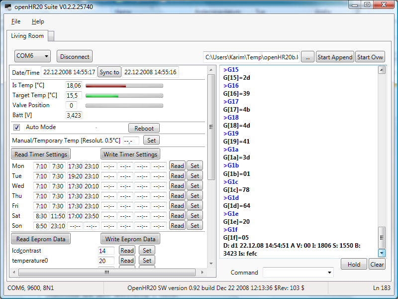
Wow this looks good!
Will try it soon!
Karim, could you assure in your code, that the COM-port-stuff is not too
much nested to the GUI-stuff.
This would make it easy to port your application to wireless HR20
control.
Would probably require some Addressing-Layer in your Programm.
Communication would the go to a "RFM-Gateway"
(= FTDI<=>Atmel<=>RFM), which would probably not be totally transparent
to your Programm.
The RFM-Gateway could do of course the HR20-comm totally transparent
(especially since FTDI is a Comport) but a more generic firmware in the
Radiomodem could make it a litte more flexible (use it as
remote-therometer-receivre as well etc).
But your Screenshot looks good! Will try it soon, wish i could code in
.NET ;-)
I wrote a short Status-Update about the Wireless-Branch in the Project's
Artice Page.

http://www.mikrocontroller.net/articles/Heizungssteuerung_mit_Honeywell_HR20#The_Wireless_HR20_Branch

(@Jiri: sorry it is in german, but it contains nothing you do not
already know anyway)
Guest
#1087583
Hi

Thank you for your answers.

@Frank:
I am sure the wheel was on the "all open" position, before I mounted it
on the valve. I am not sure whether the problem can be solved by coins.
If the distance would be too large, the pin of the valve would be out
and the valve open. In my case the valve is closed after three days. But
still I can give it a try.

@jdobry:
I am not sure I correctly understood what you ment. What is a SW? And
how did you change it?

Thanks a lot,

Robert
Guest
#1087889
@Robert:
Original software in valve is 2.04 from Honeywell. We don't know how to
set it via serial line, how to bugug problematic situation etc.

Therefore we wrote complete different SW for this valve. It have some
extensions for debug and some more functionality. And don't have "cold
valve" problem as is discoverd by you.

For change SW you needd JTAG programer, see to this thread history.
Guest
#1087949
@Karim L.
I was try your SW 0.2.2.25740 version. And this is result:
- not able to run under MONO, It use too many non implemented functions
in mono.
- it always use anti-aliased fonts and don't respect setting in windows.
It is hard to read on hudge monitor with high resolution
- layout have fix size, unable to use bigger window
- About dialog contain information about GPL II license, but where it
sources?

Thanks for this SW, it can be useful. It's pitty that it can run only
under MS Windows. Many of us have another system.
Guest
#1088422
@Robert: If you dismount the head you can check the position of the blue
weel - is the pin all in or all out or in between? You can get mor
Information when you connect yor PC to the serial port of the HR20. But
keep in ´mind that ist side is in 3,3V-logic.

By the way, what is the easyest way to connect the HR20 to the serial
port of a PC? Found this Beitrag "1 Transitor + 2 Widerstände = Verwirrung",
intended for I2C but should work on RS232 too (?).

@Karim: very fine - it runs on my XP but not yet connected (s.a.).
Could your progy also work on an I2C-bus? I have 25 m cable going along
every radiator in my flat. It would save me from laying my hands on
every HR20 twice on each holyday :)

Frank
Guest
#1088508
@Frank:
easyest way to connect the HR20 is use MAX232 for serial line or another
cheap solution is use USB cable with USB->serial convertor for mobile
phones. (Ulder mobile phones don't have USB and this cable not contain
level changer for RS232 line, but use 3.3V logic). Example is (tested)
KQ-U8A cable ( http://stephane.aubert.free.fr/KQ-U8A/ ). I buy each by
aprox 3.20 EUR


I2C-bus is not supported on OpenHR20 software. Except this I can't
recomend I2C bus over all valves. This bus is not protected to noise and
cables will be too long.
Guest
#1088762
Hey Karim

first look on your tools is all great. It works fine - but: were can i
select the temperature for each on/off-time pair (snow/moon/sun on LCD)?

Great work!
Frank
@Mario,
the COM Interface is placed in an one class. I will add an SW interface
to it, which all communication classes has to implement, so that a
seamless integration of any interface will be possible.

@Jiri,
the Suite is for me also an interesting technology project, since I have
not written until yet a WPF application and I did like to use other
technology stuff like reflection, data binding, user controls, which the
.NET Framework offers, because I will need it at work next year.
- MONO is always behind the latest technology. It takes a while until a
full implementation is available but if I interpret it right, as I even
so they offer already the .NET 3.0 function set. I reduced the level of
.NET in the project to 3.0 and until some minor changes, it works as
before.
So the next release will require only .NET 3.0. Hope this helps for the
Mono user. But I have no experience with Mono.

- The code will be made public after I have added comments and
reorganized the code a bit. May I add the code into a new folder in the
SF openHR20 project? Would that be ok for you?

- The size of the windows is currently fixed, because I don't know how
to change it yet. It is different from Windows Forms but I think still
not difficult. But that is on my list for change as soon as I know how
to do it.
What monitor resolution do you use. My one has 1680x1050 and I can read
it well.

Windows is the most used OS platform and .NET is quite powerful. Since I
know how to program in .NET, it is the fastest way for me with
acceptable effort to get a complex program although it is still a lot of
work. And with Mono, even if it might not be possible yet, will open the
door for other platforms. Hope you can live with that point of view.

@Frank,
the level shifter would allow to connect the RS-232 in parallel, but a
special protocol would be required for communication which the I²C Bus
(TWI-Two Wire Interface) has already implemented (master/slave, clock,
addressing, collegian handling...). But in principle not a bad idea to
use a level shifter plus a special protocol. I have also installed a
cable ring to all heaters but planned to use I²C bus. The Atmel
controller supports I²C bus. And the nice thing is, the needed TWI Pins
(SCL (same as TCK, pin 4 of the connector), and SDA (TMS pin 3)) are
already routed to the module outside connector. What we need is an
interrupt routine which roots the traffic and at the PC a TWI to Serial
or USB converter. An additional option is the 3 wire USI connection. But
Jiri might be right, that long wires can be a problem for the signal
edges although the overall speed can be as slow as wished. We will see.

The temperature can be set in the eeprom block (temperature0-3), but it
is not a nice way because of the required calculation of the necessary
value. Also missing is the possibility to assign this temps to the
switching time. I will add both later.
Guest
#1088898
@Karim
An I²C-Bus slave for Attiny was in the last issue of Elektor in germany:
http://www.elektor.de/jahrgang/2009/januar/i2c-slave-kernel-fur-attiny13-2313.769117.lynkx
The best is, no special port is needed for it. We could use any line -
especially the serial lines, replacing the RS232 by the I²C.

By the way, in the same issue there is an article about to conntect a
RFM12 to AtMega.

@jdobry
I²C-Bus as a house-bus you find in Funkschau 9/2004 or at
http://www.hauscomputer.gmxhome.de/. It seems very simple.

My idea was to connect each rondostat with a power-line instad of
batterys, I²C-Bus for Comunication and a PIR-switch. The later is to
overide energy-save-mode if a person is in the room (e.g. school ends
earlyer). PE2 is still free!?
Guest
#1088963
I2C have some problems. Generaly it have open-collector bus. This mean
that logical "1" is defined by resistor. On long cables, it have slow
edges and mainly it have zero protection for noise. This problem can be
fixed by active current injection on level change, but it need special
chipset. Except this we can't use hardware support on HR20, because it
need pins PE5 and PE6. Pin PE5 on HR20 is connected to ground, and it is
not possible disconnect it without remove chip. SW implemented I2C is
possible but I thing that RS485 is better for cables in home. RS485 HW
is extremely simple, see to
http://www.datasheetcatalog.org/datasheet/maxim/MAX1487-MAX491.pdf

But you can to do anything that you want, Source is GPL and you don't
have any restriction. But because I have not cables, I must use wireless
comunication.
Guest
#1090923
Experience after 4 weeks on 4 valves

- valve have more actions compare to original SW. It must be improved.
Have anybody any idea?

- battery low detector is not sufficient. At low battery SW usualy
detect flase Error3 before battery low. I have some ideas how to imrove
it, but your ideas is also welcome.

- current temperature measure convert each measure to tempereture and
calculate average from last minute. Result after average have better
precision than is measured (overscan). But it can be reason to many
action on valve. I will try prepare version with average from RAW ad
data and calculate temperature from result. Overscan can be used or not,
i don't know what is better.
Guest
#1091386
HI @ all,
i have some questions.
is there an bootloader also implementated, so it is possible to flash a
new Firmware over the Uart? The problem is, that i have the
JTAG-Ice-MKII debugger only for the next seven days, and than i have to
give it back.

The next think, i want to know. Is there a posibility to use the SPI,
i want to connect a can tranceiver to it, i saw that the pins PB0 to PB6
are use for the buttons and the engine.

wbr
Peppe
Guest
#1091425
@peppe: It is possible use bootloader to flash this device. But I am do
not use it.

SPI: It is near ti impossible reconnect buttons to other pins. Therefore
only one chance is SW implementation of SPI protocol. See to branch for
RFM12 wireless communication (on development, not work now)
Idea: PE2 is free to use and avail on the connector. I'll try to connect
it to a PIR motion sensor.
If there are some events (PE2 is PCINT1 and can serve as an interrupt
source) within a given time, the room is known as used and the
temperature will be set to "comfort". If no motion is detected,
temperature wil go to normal value given by timer.
I will modify a cheap motion detector whith a relay.

I think i will need a timer for it - Timer1 is not used yet?

By the way - how are you using the simulator? Is it possible to simulate
the switches too? I only reach "E2" due to PB0 is always going back to
0.
Guest
#1096582
@Frank E.

If you are not using RS485, PE2 is free. (used for debug, disable it on
debug.h)

Timer1 is free and it is disabled (you must remove this power save
feature)

I am not using simulator, just JTAGICE debuger connected to real HW. But
on simulator you can manualy change pin status when SW is stoppend, or
you can create input files, see to atmel docs. But I thing, that it is
too complicated.

Jiri
Hello Jiri and all,

in my holidays I modified the code to work with the Thermotronic
thermostats. I did this by using #if - #endif stuctures to make the code
working for HR20 as well. Maybe you want to include my modifications in
the SVN - a new branch should be unnecessary.
The important differences between HR20 and Thermotronic are:
-different pins for switches etc. (scheme of TT can be found in another
thread)
-no enable-pin for motor-pwm
-hardware USART used for motorencoder (so i actually disabled all debug
functions)
-different thermistor - I modified the values but I´m not sure they are
correct. Maybe the have to be updated in future. The Thermotronic doesnt
show the measured temp so I cannot analyze as described in doc.

Thomas
Guest
#1100098
@Thomas V

Modification for Thermotronic would be nice. Please contact me by email
for access to SVN or send me patch set.

Schematic is here
http://www.mikrocontroller.net/attachment/29357/schematic.png
Hi,

first I want to thank you for creating this project! I do some
home-automation and this is just what I was looking for.

Yesterday I bought me a HR20, connected my spi-programmer to the
corresponding pins and set the fuses to l:0xe2, h:0x9b and e:0xfd.
Then I uploaded the firmware I compiled out of the current SVN rev. It
worked immediately but very unstable (random hangups). So i took the hex
and eep files from the repository and it works like a charm.

Do you have any idea why my self-compiled version fails? I used the
Makefile from the repo with only one little modification: my avrdude
doesnt know the atmega169p so I hardcoded the atmega169 for avrdude (not
avr-gcc).
Environment is Linux with avr-gcc version 4.3.0.

Best wishes
Björn
Hallo!
Das hier ist ja mal höchst interessant. Bin mittlerweile auch im Besitz
eines solchen Reglers.
Ich habe verdammt lange nichts mehr mit einem AVR gemacht!

Wie bekomme ich mein Rondostat umprogrammiert?
Mir steht ein STK500 zu Verfügung. So wie ich das hier gelesen habe kann
ich das ganze nur mit einem JTAG programmieren, den das STK500 nicht
hat?

Bekomme ich das doch noch recht spontan programmiert?
Gibt es eine Schritt für Schritt Anleitung?

Gruß,

gammla
@gammla
Sorry, keine Anleitung bis jetzt - ist auch kaum möglich, da stark von
dem vorhandenen Gerätepark abhängig.
Ich bin so vorgegangen:

1.) JTAG Programer gebaut. Ich habe dazu ein ATMEL-Eval-Board von Pollin
angepasst. Anleitung findest Du bei Evertool-Light
http://www.siwawi.arubi.uni-kl.de/avr_projects/evertool/#etlight Dort
ist auch die Beschreibung, wie man die Firmware und die PC-Software
beschafft und installiert. Achtung: Es muss ein anderer Quarz ins Board!
Du brauchst auch nur den Teil fürs JTAG nachbauen - 1 Quarz, paar
Widerstände, 1 LED und 1 Kondensator.
Die Steckerbelegung am HR20 findest Du in der Analyse
http://carluccio.de/images/e/e1/Hr20-analyse.pdf. Ich habe 2 5-polige
Platinenstecker benutzt, wie sie in PC für die Gehäuseanschlüsse oft
verwendet werden.

2.) Aktuelle Toolchain für den Compiler installiert (Win-AVR) und
danach das Atmel-Studio 4 (Nicht Studio 32!). Hinweise dazu auf der
Seite von ATMEL.

3.) Das Repository mit den Sources geholt -> siehe dazu
http://www.mikrocontroller.net/articles/Heizungssteuerung_mit_Honeywell_HR20#Subversion_Repository

4.) Anleitung zum Übersetzen und Übertragen im Repository unter
1 | |
Das Device im Studio festgelegt als JTAG ICE.

Aufwand: Recherche 4 Tage (kannst Du Dir hiermit sparen), Löten 2
Stunden, Software 3 Stunden (aber nur wegen der alten Version von
Win-AVR).
Sieht nicht gut aus, tuts aber...
Hi,

I've written a little tool for the linux/*nix console to communicate
with openhr20. It's very basic, just for my needs, but if there is
interest, I will extend it. With it, you can set the current date/time,
the wanted temperature and the mode. You can also get the status.
To compile it, you need cmake. If chosen this as it makes it easy to
compile software for different architectures.

Björn
Guest
#1106328
@ Björn Biesenbach
nice tool! Do you wan't to place this project into SVN? If yes contact
me by email.
Ok the tool can now be found in the svn under tools/
Guest
#1107102
I made hudge experimental change in motor controller. Version before
this revision use constant PWM for open and another constant for close.

This experimental revision try to use constant speed and try to control
PWM.

Benefits:
- we can use slower movement and it is more quite
- I hope that it will more resistant to false "Error3" detections
- speed is independent to battery voltage

Second experimental change:  limitation of "P" part of valve position
controller. "I" part of this controller will found valve position inside
regulation area. I hope that it will reduce motor movement outside valve
regulation area. It save battery. It use config.P_max eeprom constant
and it can be improved.

Because it is EXPERIMENTAL, it is not in SVN main trunk. If you want to
test it, please use "Rev 152" from rfmsrc branch. Change "#define RFM 1"
to "#define RFM 0" in config.h


If you want to help with development, PLEASE SEND ME LOGFILE FROM YOUR
VALVE. Thans.

Jiri
Guest
#1107122
I forget to one warning. Rev 152 have changed numbers of settings in
eeprom. Please see to eeprom.h
Hello Jiri and Forum!

@Jiri:

PWM: could you explain a little about, what the use PWM in motor control
is at all?
I thought, motor speed is not important at all because the valve
position is not calculated by motorspeed (==PWM?) and motor's runtime -
it is calculated (much more exact) by lighteye pulse counting - which is
speed independant.
Could you tell me/us a little about meaning of PWM in motor control?

RFM: sorry, i did not have time for working with RFM last weeks. I hope
i will find some time next week and/or the followings.
Guest
#1107254
Rev  152 and 153 in branch rfmsrc is buggy (measure wrong motor
calibration, will be fixed today, please wait.)

Motor speed is not significant for valve position. But old versions use
constatnt pwm for control motor speed. This has this problems:

- high pwm constants are noisly
- high pwm constatns have hard touch on the end of motor movement range
- low pwm have problem with false "Error3" detection (motor can be too
slow)
- speed depend to actual battery voltage, therefore is near to
impossible find this constants for open/close

Jiri
Guest
#1108212
Bug on motor calibration is on "manual callibration". It is fixed for
rfmsrc branch in Rev 155

New motor speed controller looks nice and better than original constant
PWM.

!!! Bug is not fixed on main trunk now !!!

I wan't to find maintainer for version 1.00 (main trunk)
We need to integrate changes from Rev 155 (bug fix)
We need to integrate changes from Rev 152,153 (motor speed controller)

Any volunteer?
Guest
#1109193
Hello,

Motor speed controller is in SVN (Rev 158 in trunk / Rev 157 in rfmsrc).
If you can, send me log frou your valve/HR20 combination.

- If you will have problems (heating still cold or too hot) try to
increase config 0x0b

- If your motor speed is too high decrease config 0x12.
- If your motor speed is too low increase config 0x12.

Jiri
Guest
#1109347
I have best results with "I" constatnt  = 1
You can set it in service menu or by COM (S0601<enter>)
Current default value is 3

Can you confirm this result? I will change default value.

Jiri
Hi Jiri,

ok the hex file from trunk/source 158 seems to work here. What log do
you want to get? The output while adjusting or just any motor movement?

I still have the problem that my self-compiled hex does not work :-(
Don't you have any idea what the reason could be? Which compiler version
do you exactly use?

Bjoern
Guest
#1109509
@Bjoern:

I need complete log (motor calibration, and all motor movement, both
have some significant information)

About compilation: I know only gcc version, but significant is also
version of AVR lib. Version? Distribution? You can try to disable
"#define  TASK_IS_SFR 1" to 0 (disable interrupt optimizations) and
replace "OPT = s -mcall-prologues" to simple "OPT = 2" in Makefile

Jiri
Guest
#1109778
If you want to use rev 152-158 please change configuration 0b to 0x32
(hex) It contain bug (Valve can still close, same bug as original SW see
Datum 21.12.2008 13:28 in this thread). I know why and I have solution.
It will be fixed later.
Jiri
Hi Jiri,

thanks for your unrestless effort. Propably tomorrow I can send you a
log file.

In rfmsrc you moved some files but didn't check in the appropriate AVR
Studio aps project file. The Studio claims about missing files.

openHR20 Suite:

Unfortuantely MONO does not support WPF (only Windows Forms) and there
are no plans yet to do so although parts of the community see high need
for that (otherwise MONO is ded on the long run).
It would be possible to rewrite the Suite to run under Windows Forms
instead of WPF, but since there is a Linux SW now available, it is not
needed and the more flexible solution would be a WEB application.

Nevertheless I extended the Suite between christmas and new year and
this could be released in a few days, if anybody likes to have it. New
is a script sending feature (for ease use, can be derived from log
file), the assignments of switching time and temperature (0..3) can be
done now, the temperatures can be set with more comfort and a bug fix
was done.
May I add the code to the SVN?

You have been right, the pins for TWI are not routet out, I did look at
the wrong port. Using RS485 is a good idea.
Guest
#1110690
@Karim L:

I thing that your tool in SVN will be welcome. Please add it into
"tools" folder.


@All:
Please try Rev 159 and send me log. Current default "P" limiter (config
0b) in SVN is 100 (0x64 hex). But I want to test it with smaller value
(ex 32 = 0x20 hex). Please change it.  This will reduce motor movement
outside live regulation arrea, but it is not fully tested. Bug from last
rev is fixed (I hope).
I want to have log file from 10 hours or more (integration of controller
error is slow)

Jiri
@Jiri,

Yesterday I flashed REV 159, changed 0b to 32 and logged a calibration,
window open/close and temp regulation over night. Log is still recording
and I will send it to you in the evening today when I am back from work.

But what I found in the morning is, that the switching times I set are
not used. I can set them and read them back which shows the correct
values but they are not used. Is this a bug or is there anything else to
set?

I have also a Thermotronic module and the code shows adjustments for
this module which can be enabled per compiler switch. Is this
implementation complete and does it work?

Regards,

Karim
Guest
#1111289
@Karim L: switching times working without problem for me on all 4 walves
with OpenHR20 SW. It has not in MANU mode? Strange, it may be new bug?

Thermotronic: I thing that it works, but I haven't this HW to confirm
it. This modification is done by  Thomas V. and I only review it. Main
difference from HR20 is missing communication (pin is used for something
else) and no PWM control for motor (haven't support in HW).

Can somebody confirm to me that original SW in Thermotronic not use SW
implementation of motor pwm (HW is not possible)?

Jiri
Hi Jiri,

I will try to find out if the Thermotronic uses software PWM next week.
At the moment i have less time. I hope I can finish my modification for
new timeroptions next week, too.

@Karim: except for missing communication and missing PWM my Thermotronic
works quite well. I think modification for RFM12 will be possible. The
RX-Pin of hardware usart isn´t used, too. So maybe it will be possible
to implement an unidirectional communication over RS232 for
configuration and so on. Another solution would be a software-uart, but
this would need much memory...

Thomas
@Jiri,

I don't think that manual mode is set, but may be you are rigth. I will
check that later.

@Thomas,

Thermotronic schematic diagram can be seen here
Beitrag "elektronische Heizungsregelung mit Thermotronic", but you may know that
already. Would it be possible, to release tx pin an use instead one of
PE4..PE7? It would enable full communication as HR20.
Guest
#1116082
Hi there,

I'm going to try all the stuff as soon as my JTAG Adapter arrives!
So far it sounds soooo nice.


Meanwhile ...

Do you think it's possible to take a new software branch for
having more than 4 switching times, let's say 6 or 8 switching times per
day?
Additionally I'd like to have more than 2 temperatures, say 4
temperatures,
e.g.

07:00-09:00   21 Celsius
09:00-16:00   19 Celsius
16:00-22:30   21 Celsius
22:30-07:00   18 Celsius

How can this be achieved so that it doesnt conflict with all the
radio/wireless approaches there are?

Please gimme some helping hand, for what I've seen so far, I can change
the software in C with some version of the AVR studio... Am I right?

Having more than 4 switching times, together with more than 2
temperatures
will surley let me reprogramm all the setup stuff etc.

What do you think?


Kind regards
Thomas Reifferscheid
@reiffert,

this work is already done. Thanks to Jiri and Dario, the OpenHR20 SW
allows 8 switching times per day and 4 temperatures they can be assigned
to.
Ok, the original Thermotronic doesn´t use PWM. I think it is possible to
change pinconfiguration to use hw-uart but you have to do changes on the
pcb so I think this would be a solution for only a few people. A better
way would be to use a rfm12 wireless connection.

Thomas
To integrate a rfm12 module, a user has to open the Thermotronic module
an solder wires as well. Although it meight be a bit less complex than
to cut a strip on the board and rearange a connection, still some
wouldn't be able to do neither of both.
Here is an updated version of the hr20cmd tool. It has the ability to
get and set the timer slots now.

Björn
Hello Jiri, Dario and the other guys from HR20 wireless!

I read Jiri&Darios Wireless Spec and have some annotations about it, i'd
like to give now.

I hope it doesnt sound inpolite, it's for sure not meant that way!

Ok, nice evening!

*** ***

4.2. Sync Packets
Did i get this right? the Master sends regulary Sync-Frames containing
the current DateTime every :00 and :30 second? (:00 is enough anyway i
think).
Here i see a bootstrap problem:
If a slave hasnt a synced clock yet (regardless if he knows that his
clock isnt synced), he doesnt know when the time Slot 00 occurs:
So he has to switch on the RFM receiver for about a whole minute, hoping
he receives a Sync Frame, which is battery consuming and costing program
space.
I would rather suggest, that a Sync-Packet is just a
SETDATETIME-Command, the Master sends to the Slave,
after the Slave sent a BroadcastStatus packet (in his Timeslot with
Second=OwnAddress).
Then the slave's clock can be synced as well.

I dont agree with your statement that Date&Time is needed for preventing
replay attacks:
A Timestamp is worse for replay prevention than a random number.
4 byte MAC Code is totally overkill! This is wasting battery!
Beside, longer packets have a higher propability to get lost over the
air.

5.2 Keys
I agree that it isnt recommended using Masterkeys in encrypted
Communication.
But derived Keys like Kmac and Kenc make ONLY sense, if they are derived
from the Master Key more than one time within the life time of the
Masterkey!!!
Otherwise it doesnt have any impact on security.
If Kmac or Kenc is broken, Km is worthless as well!
I think you mixed that with the idea of session keys.

General Critic: The packets are too long, too many syncs from master the
slave might not hear anyway, derived Keys that dont improve security.
A nonce derived from a datetime and a packet counter is predicatable!
A nonce = rand() is much better.
What is the CRT ? did you mean CTR?
Does all this fit into HR20 left codespace anyway?
Guest
#1128393
@Mario:
4.2.
- We need broadcast date/time for encryption also.
- boot strap is not problem. It happen only ONCE afret battery change
and price is 15mA on 30 second (maximum) It mean 0.002mAh - not problem
- sync packet on 00 and 30 is not exactly same. It is needed for force
communication from selected slave. Time slot 31-59 can be used as block
for one slave long communication.
- use random number rater than time is worst because it complicate
protocol, try it and you can see. For security is ony byte random number
nothing. Two bytes looks better, but if false feeling
(http://en.wikipedia.org/wiki/Birthday_paradox)
- 4 byte MAC code is nothing, you must calculate energy. Cost is
4.6e-5mAh per packet. This mean that 132000 status packets (one year
average) take 6mAh. It is nothing.
- For save energy we MUST have very accurate time synchronization.
Enable receiver for 1 second have same cost like send 360 bytes!

5.2 I can't agree, that it not improve security. It is no way how to
calculate Km from Kenc or Kmac. This mean that if you have Kmac you are
not abble calculate Kenc nad vice versa.

CRT is misstyping

Jiri

PS: It is not pollite for others discus this document on this thread
when it is not public now. (it is not secret, we will add it on SVN
later)
Guest
#1131533
New revision 175:
Changes:
- controler use new configuration for linear "P" gain
- controler configuration for quadratic "P" gain
- new config option (0a) for min valve position (default 30%)
- new config option (0b) for max valve position (default 80%)
- optimization

Improvemets:
- linear/quadratic controller have best result for me (send me your log)
- valve min/max setting save batteries because not all range of valve is
active. If you have problems (valve still open or close) please change
it. I am not abble to find algorithm to find it automaticaly (every idea
have some condition when must fail. I belive that range 30%-80% is
correct for major part of valves, but you can set narrower range and
save more battery energy.

If nobody found any problem I plan release Rev 175 as STABLE version
1.00.

If you want to do something:
- doxygen comments need improvement to generate USER DOCUMENTATION
- create Thermotronic patch for rfmsrc branch
- create schematics picture for RFM12 master HW (text specification is
in SVN)
- I want to find maintainer for stable 1.xx version. I have last one
HR20 without RFM12 modification and I will not have HW for test this SW.
Hello Jiri and OpenHR20 Team,
first of all, sorry if my comments on HR20 wireless spec were misplaced
and sounded inpolite, both wasnt meant so!

today i checked out the openhr20 from svn and tested the rfmsrc-branch:
i could verify, that the (interrupt driven) RFM packet sending now works
correctly, even for long packets (either my receiver was programmed
wrong some months ago, or the old openhr20's sending code (non interrupt
driven) swallowed some bytes), but anyway this looks good to me!
but i got one strange compiler message, saying that this code
1 | |
2 | |
3 | |
creates this warning:
main.c:223: warning: implicit declaration of function '__vector_2'
it looks to me like a typo (PCINT0 is hard coded beside that) and i
wrote
1 | |
2 | |
3 | |
 instead, raising no warnings, and running correctly ...

until i mounted the valve for the motor calibration to start, which
makes the HR20 reboot in infinite loop every few seconds. (reboot,
running till blinking "2008", reboot, ...).
it also showed this reboot loop with #define RFM 0
could this be a consequence that moror control isnt via PWM?
any ideas? sorry i have no logs about that (yet).
regards,
Mario
Guest
#1133691
This code:
1 | |
2 | |
3 | |
is correct:

1) please don't remove branches around macro body or use ";" on end, it
make problems if you use macro in expression
2) PCINT0_vect() is dummy call interrupt to insurance that no interrupt
will be lost (signal is level based, interrupts is on edge)
3) If you want to remove this false warning, add this
1 | |
into rfm_config.h


Reboots: I thing that you are use external power not bateries. Right?
Problem is that old code has problem with motor movement with older
batteries and create false positive "E3". Therefore from Rev153 motor
have "I" controller for speed stabilize and motor startup use
config.motor_pwm_max value. This works amazing on batteries, but worst
with external power (HR20 have not any capacitor for absorb power shock
from motor start because it is not needed with batteries) With external
power you must add big capacitor into power lines. If you use USB as
power source it is worst, because USB have current limitter (USB
specification) and power line shock is hudge.
Guest
#1139880
New release candidate  for ver 1.00 is Rev 180.
Please test it.

Changes:
- fix setting to AUTO mode
Guest
#1140067
Information about wirelles:

Rev 181 is just proof of concept for bi-directional communication. It is
not usable for real live, I must refactor some code and add real
functionality.

Jiri

PS: I am not abble maintain 1.00 versions after release. I have not Hw
and I have not time also. Any volunteer for maintain it?
Hello Jiri and the other guys from the 'development team'.

Fantastic project, the code worked more or less 'out of the box' for me.
No problems with compiling and exactly the features added to the
original code that I missed.
I have also been using the RFM12 in other projects and have tried that
modification during the last days (external RFM12 connected via JTAG
pins). After adding some code to get the necessary information like set
value and measured value for temperature and the valve position sent via
RF I can now at least log the data from one thermostat without cables or
a notebook in the bathroom. I hope that this will help me to fix some
problems I have with the regulation characteristics using the default
settings.

I use two HR20 in quite small rooms (toilet ~3m² and bathroom~10m²) and
the regulation with OpenHR20 and default settings works much worse for
me than with the original HR20 firmware. When heating up in the morning
(step from 15°C to 21°C) this happens much slower than with the original
software but there is also a big overshoot. Than i quite often see a big
permanent difference between set value and real temperature without any
reaction on the valve setting. Strange, but as already said I will now
first log the data before telling too much nonsense. And I know that
these small rooms are very complicated in terms of regulation compared
to larger ones. The doors and windows are also permanently (or at least
quite often) opened and closed in these rooms and this makes everything
even worse. But as already said, the original software seemed to handle
this much better.

To correct problems like this or workon them, I first have to understand
the code and function of the controller better.

One comment on the 'RFM' version: I have a blank display after some
seconds only with this software. When changing the set value with the
wheel, the changed value is displayed correctly again and then after
some seconds it disappears again. The 'normal' version without RFM12
works ok.

That's it for now, keep on the good work. And maybe someone has a
suggestion, which parameters I could touch to improve the regulation.

BR,
Jörg.
Hello Jörg,

I can confirm, that the software does not regulate the desired value
exact (about 0,8°C lower than set) and also it does not open the valve
wide enough in my opinion to reach fast the desired temperature. In my
30m² living room I have no overshot of the temp. The current setup might
be ok for a large heater in a midsized room, but it is not optimal yet.
Problem may also be the different valves (where is it completely open
and closed?). The SW was optimized by Jiri for less movements and saving
battery energy. Further work is required.
It would be good to have an algorithm, which adopts automatically to
some parameter and may be also predict the temperature which will be
reached on a valve setting. For that, a pulse response characteristic
could help.
Open the valve 100% for a short time close it completely. Measure how
long it takes until the temp rises, until it reaches the maximum and how
it does fall. Calculate the mathematical formula and use it ;-).

Regards,

Karim
Guest
#1147124
@Jörg Becker: thank you for feedback. I know that default setting after
last modification is not perfect. It works for me (used on 4 rooms,
bathroom still use original SW for comparation)
Karim have true, we have to many different conditions (valves rooms etc)
but too less data for final setting (send me you log).
You can try change setting:
PP_Factor (05): proportional gain for quadratic error
P_Factor  (06): proportional gain for linear error
I_Factor  (07): gain for integrated error

Try increase I_Factor, it can solve problems with small rooms. If you
can, send me log file.

RFM12: this state still in pre-apha state. Too many parts is changed,
but not finished. Could you send me your modification on RFM12? May be I
can use some part from it. Current code will need some special SW/HW
called "master" to control wireless network and for encryption. It make
it incompatible with simple wireless listening and loging.

@Karim L.: I fully agree, that current controller part can be improved,
but it need some suficient matematical model. We not have it.
Jiri,
I am sorry, I simply do not have enough time at the moment. My logging
attempts were not successful partly because I have problems with my
circulation pump not working correctly (no, not with mine, but with that
of my heating system :-) ).
When the pump works ok and the water temperature is not too high
(dependant on outside temperature) the regulation with default values is
not so bad, although I still sometimes (?) see permanent differences of
nearly one degree like Karim.

One of the reasons why I want to have the RFM12 solution is, that I want
the thermostats to do the regulation only when the circulation pump is
running. And this is 'intelligently' controlled by my heating controller
(Schäfer Domoxxx something). In times when the pump is stopped (variable
interval at night with start time in the morning depending on outside
temperature) the thermostats shall go into off position. The same goes
for times when the pump is completely stopped due to high outside
temperatures (programmable, set to >17°C in my case).

Regarding code with RFM12, I used your code nearly 100% and just added
some extra bytes for sending set temperature, real temperature and valve
position every two seconds. Worked ok more or less as I did not 'know'
(or understand the code enough) that this software does not switch the
temperatures to the preset values like the normal software does in
automatic mode. It seems to be waiting for a master command to set a new
value? So my remote (RF) logging attempts were not successful. Have to
dig deeper into that code first (or wait for your solution :-) ).

BR,
Jörg.
Guest
#1152423
I have a problem with version 180.

I had the valve behind a curtain. So it was very hot but the valve was
full open! The temperature was shown at 9 °C (I measured about 40°C with
another thermometer).
I pulled off the HR20-head and watched the temperature, while it cooled
down. It decreases from 9 to 0.0 °C and then it jumps to 25.5°C (in my
opinion the real temperature at this time).

Is there a problem with high temperature measuring?

Ronny
Guest
#1152836
@rhb: thanks for bug report. I was repeat it and this bug is real. I
will fix it.
Hello Jiri,

on last Sunday I flashed REV 180, but couldn't log long enough to make
some effects clear. Today I discovered also a jump in the temperature,
which I couldn't explain (within a few minutes from 16,76 to 17,26 then
back to 16,76, 17,76, 17,30 and 16,82 which looked strange to me.

I have the feeling, that the temperature send to rs-232 and internally
used are different, which could be the reason for the temp difference of
about 1°C which I still can see.

When I increase the set temp from 17,5 to 18,5 °C the valve will be set
to about 50 which still does not open the valve (at least not much) and
even after 30min the valve will only be opened slightly to 52 or 53
which is still not enough. As I have that logged more clearly I will
send you a log.

Concerning a new regulator model, I have unfortunately no experience and
would have to do a lot of experimenting and development work to get
something reasonable to work.

Regards,

Karim
Guest
#1152883
Rev 192 is bug fix for measured temperature > 25.5.

- temperature was measured correctly
- Rev192 is new release candidate for 1.00 version

@rhb: I was found bug only on LCD value, can you explain it better? What
was valve value on LCD on "%".

Jiri
Guest
#1152887
@Karim L: internaly used temperature and RS232 log is SAME values. It is
past 15 second average.

Only one exeption is debug output (DEBUG_PRINT_MEASURE). This is RAW
values before 15second average. This debug is DISABED in default
compilation.
Guest
#1153473
@Jiri:

Please take a look to the following source code lines.
From my point of view the type of the variable valve is changed too
often and may force neagative effects.
1 | |
2 | |
3 | |
4 | |
5 | |
6 | |
7 | |
8 | |
9 | |
10 | |
11 | |
Artax
Guest
#1153721
@ Artax:
All this lines is correct:
temperature can be measured - unit is 1/100 degree(int16_t)
temperature can be wanted - unit 0.5 degree (uint8_t) - calc_temp()
macro change it into 1/100deg unit and int16_t type.
valve position have int8_t variable and range 0-100

PS: I know that it is not best practice change types often. But we don't
have a choice, because it was save many bytes in RAM and Flash. Current
situation : incomplete RFM code take 15102bytes form 16KB Flash. This is
one of many "ugly" parts of code. Most ugly is non existed division into
layers and interfaces between this layers. We dont have space for it.
Guest
#1153732
@ Artax:
signed values on valve is remaining code from old valve renage (-50 to
+50).

It can be cahnged to uint8_t
Ex:
1 | |
And it can save 4 bytes in flash.
Guest
#1153772
@jdobry

measured temp is ok in rev. 192, thanks for your very fast response!

The overheating was my fault, your question was the right hint: the
default min. valve position in eeprom (30%) was to high for this small
room and valve. Now I set it to 5% and everything is ok.

Ronny
Guest
#1154658
@rhb

Valve limitation is not depend to room size but only on valve type.
Every valves have wider range than active part. This is for my valves.

  0-45  - valve is closed, when I try go from 45 to 0 force for movement
growing and this have not efect for regulation but big effect to battery
live and gears abrasion.

  45-70 - this is active part of valve, in this change valve position
have effect to water stream

  70-100 - valve is open, movement of valve have effect near to nothing.

All this values are not exact and it depend to valve type.
Guest
#1154762
"All this values are not exact and it depend to valve type."

Not only valve type but even more on the pressure the water pump for the
heating water builds up.

Especially modern self adjustable water pumps can be a real nightmare in
this sence as the pressure in smaller rooms can be quite different
depending on how the other rooms behave.

I had the situation where the water pump would detect night shutdown for
some reason and reduce its power significantly without obvious reason.

Turning this feature off reduced my problems, however I did not even
know it had this feature as I had to open the pump to get to some small
dip switches to control this.

Axel
Guest
#1155154
Hello

I have buy an other HR20

www.thomas-peterson.de/h20/front.jpg
www.thomas-peterson.de/h20/back.jpg

I will draw a new circuit  diagramm for this.
Guest
#1155326
@Thomas Peterson:
It looks like Thermotronic.

Compare it with this picture:
http://img407.imageshack.us/img407/8021/thermotronicplatinekl2.jpg

Schematics is here:
Beitrag "elektronische Heizungsregelung mit Thermotronic"
Guest
#1156670
Hello Jiri, Karim L. and the other team-members from the 'development
team'.

Very good, phantastic project, I´m not a electronic specalist and a
managed to flash 3 hr20 (original v2.04) with the guidance in this
forum, (currently I use the latest F0.97 rev.192 without rfm) for me it
works fine so far. But i have also an older hr20 (original v1.xx) and
with the same interface cable it was not possible to get a connection,
it works only with the newer HR20.

For setting the hr20 i used the openHR20suite dated 22.12.2008) from
Karim L. The program works in general fine, sometimes I have a longer
waiting time for read / write the data’s but maybe this is related to my
interface cable.

If a new version of openHR20suite is available I would be interested to
test it. I had some problems with the valve range adjustment (30-80%) in
openHR20suite, this I could not find in the openHR20suite.

many thanks and best regards
reinis
@Reinis,

since the eeprom data arrangement did change, the first openHR20 Suite
release is not fully compatible. But I have a newer version, which I can
offer next week (I will return on Monday evening home, so that hopefully
till Thursday a new release can be provided). It has several new
features and supports the latest eeprom layout.

Karim
Karim,
it seems that you activate RTS as well as DTR in your openHR20 Suite
(both lines show ~+12V). Would it be a big deal to make these settings
variable with maybe two check boxes?
I am using a 'standard' RS232 to TTL converter with optical isolation,
which draws the power from the RS232 lines and needs RTS activated and
DTR deactivated. Maybe I am not the only one with such a special wish
:-)

BR,
Jörg.
Guest
#1157151
@karim,

that would be very nice if you can provide an updated Version of
openHR20suite matching the latest eeprom layout.

Can you give me a hint how i can log the data's from HR20 (Valve Pos.,
SW Temp. and Act. Temp.)i saw some recordings?
Was this done with openHR20suite (e.g. i have a recorder which would
work with DDE-Link if you provide this to other applications) or is it a
other program?

thx + br Reinis
Hello,

I'm new to this forum and I have been playing around with the new
firmware for the HR20E for some time. I just want to say that you've
done a really good job. But I've also found some minor problems:

- the parameter of the RTC_Setxxx functions has changed from int8_t
  to uint8_t. At least for hours and seconds this was not a good idea.
  The parameter can be negative if you set the values with the wheel
  and turn it anti-clockwise. E.g. for minutes you get the sequence
  01-00-15 instead of 01-00-59.

- setting of DEBUG_IGNORE_MONT_CONTACT to 1 doesn't work. In line 196
  of keyboard.c ( mont_contact= 1; ) the value should be 0. The 1 is
  forcing the E2-Error instead of ignoring it.

- After a reset setting of the year manually is sometimes wrong:
  If you don't touch the wheel and confirm the standard value of 2009
  with the PROG key the stored value is sometimes 2008 and sometimes
  2009. It depends on the current position of the wheel. At one position
  PB5 and PB6 are both LOW and at the next position both are HIGH. The
  variable state_wheel_prev is initialized with zero and so it doesn't
  reflect the HIGH values of PB5 and PB6. In this case when you press
  the PROG key a wrong KB_EVENT_WHEEL_MINUS is detected.
  I've found a solution for this but I'm not very happy with it.
  But here it goes:

  I've added the line
1 | |
  to the end of the init function in main.c. It must go behind the
  call of task_keyboard() in order to not being overwritten. I've also
  defined state_wheel_prev as extern in keyboard.h.

Regards, Ulrich
Guest
#1157685
@Ulrich Wilkens:

Thanks for bug report!

1) RTC_Setxxx and overflow: It look like bug in compiller. I know that
code mix signed and usigned types. And it is correct for 8-bit
aritmetics. For example minute 00-1 is 255 and
(uint8_t)255+(uint8_t)60=59. But compiler use 16 bit aritmetic to add 60
and I don't know why ((255+60)%60=15). This function:
1 | |
2 | |
3 | |
4 | |
is compiled wrong to:
1 | |
2 | |
3 | |
4 | |
5 | |
6 | |
7 | |
8 | |
9 | |
10 | |
11 | |
12 | |
13 | |
14 | |
15 | |
16 | |
17 | |
18 | |
19 | |
20 | |
Compiler use 16 bit aritmetic to adition

but this code
1 | |
2 | |
3 | |
4 | |
create correct result:
1 | |
2 | |
3 | |
4 | |
5 | |
6 | |
7 | |
8 | |
9 | |
10 | |
11 | |
12 | |
13 | |
14 | |
15 | |
16 | |
17 | |
Could me somebody tell WHY?

2) DEBUG_IGNORE_MONT_CONTACT - fixed, thanks
3) wheel error, I was know about this bug, but it has not priority.
Thanks for bug fix.

*****************************
fixed in Rev 195 version 0.98
*****************************
This fixed code is not tested, tell me if it solve problem.
Since I had my notebook with me and a bit time, I finished the next
release  of the openHR20 Suite V 0.2.4.23954 today. See the readme.txt
for the made changes after installation or the text below.

@Jörg, you may change the RTS/DTR signal state via the
openHR20suite.cfg. Install the program, chut it, modify the new cfg and
restart the program. Currently I did not like to add this settings to
the GUI.

Report problems and errors please.

23.02.2009, V 0.2.4.X
Current day in switching time table has style bold instead of italic
With # in command window, comments can be added for better documentation
of the log file
A detected open window will be shown in status bar
For com interface DTR and RTS signal state can be changed via
openHR20Suite.cfg XML File.
Log File can be renamed as *.scp and used as script file
Readme.txt added to installation
New eeprom layout of REV 180 supported (Attention: Incompatible to old
layout)
If an expected response is not received, an error comment is displayed
in terminal

28.12.2008, V 0.2.3.X Not released
IsTemp progress bar is green when Target Temp is range +-0.5°C, below
blue and above red.
Aktive day is shown in italic
Bugfixes on loading an saving data
Resizebale window, application starts with last size
Temp 0..3 can be set
Temp assignment to switching time possible
script execution added (see tooltip of command box)
Data names in data files changed -> incompatible

22.12.2008, V 0.2.2.25760
First release
Guest
#1158096
@Karim,

i just tried your latest version of openHR20suite, excelent !!!

It works much faster with read/write as the older one i used and data-tx
is now much more reliable.
Also your idea with the red error line is good.

thanks and br
Reinis
Karim,
thanks, works perfect for me!!!

BR,
Jörg.
Hello Jiri,

I've tested your fixes and they are working for me. Thanks a lot.

Regarding your compiler question: I'm not a compiler expert but I've
found this one:
    Beitrag "Re: reihenfolge der bits in einem byte umdrehen"

In short, it states out that gcc is doing calculations in a way that
intermediate results are at least of type int (16bit). This is requested
by the C standard and casting the parameters to 8bit types doesn't
change this behaviour.
Another thing is that avr-gcc is working internally like a virtual 16bit
machine and treating with 8bit values is defined specially.
This could be the reason that your second example with casting of the
end result is working.

Regards, Ulrich
Karim,
I found some problems with your OpenHR20Suite, but maybe this is just
because I do not use it correctly or I do not understand something.

If I read out temperature values, i get the reading 68:15 for empty
entries (--:--) in the thermostat. If I enter --:-- in the program and 0
0 for the temperature settings, the program just closes if I press
'set'.
Next, if I enter new values directly in the thermostat and then read the
timer settings again, nothing is changed on the screen. But the new
settings are clearly present in the thermostat.

Any idea what I am doing wrong?

BR,
Jörg.
Karim,
now I see that you only show the timer entries for the individual days
and not for settings the whole week (I use setting 1-7 on the
thermostat). I thought that the settings for (1-7) would be copied to
the individual days.

BR,
Jörg.
Hello Jörg,

thanks for the hints.

Week mode operation is not well supported in the program. That is one of
the open points for the next release.
If I don't want to use a switching timer, --:-- is to be set at the
module by the wheel. If I read then the time via program, I get x5A0,
where x stays for the temps 0..3 to be used and 5A0=24:00, which marks
not to use this switch setting.
The default in eeprom (see ee_timers in eeprom.h) after flashing is for
not used switching timers xFFF=68:15 which is different from above after
manual setting. 68:15 is not replaced by the suite with --:-- yet. And
even worse, if you try to enter an invalid time, the program crashes.
But I know that and in the About window I made a hint to not enter wrong
values.

I plan to add a check for all entries and I would like to use masked
text, but here MS made it not very easy to have a nice implementation.
This subject is more complex to solve as you would assume and I need
time to acquire a solution.

So don't enter an invalid time, only this range is allowed
[00:00...23:59, --:--]. Don't try to set a displayed 68:15 red from
device, because it lets the program crash.

You can switch from week to day mode by setting the timer_mode from 0 to
1 in the eeprom data block.
The week times can be set via R00..R07 command. But I will make that
available by direct setting in GUI.

@Jiri, is it required to have xFFF as default in ee_timers for not used
switches and could this values be changed to x5A0?

BR,

Karim
Guest
#1160253
@Karim L.

For not used timers I need any invalid time. x5a0 is also correct.
@Jiri,

ok, I will do a fix for that in the next release.
Hi Jiri,
I still see some permanent differences in set value and real value
without any reaction of the controller. Now I took a HR20 with newest
firmware on my desk and waited until the real temperature reading
stabilized to 18.32°C (with a set value of 19.0). Then I made some
changes on the I value. But i do not understand the result. Do you have
an explanation?
1 | |
2 | |
3 | |
4 | |
5 | |
6 | |
7 | |
8 | |
9 | |
10 | |
11 | |
I thought that increasing the I value would help the controller to get
rid of the permanent difference by opening up the valve, but the
opposite happens.
Ok, I wanted to watch this a bit longer, but after some minutes the
automatic timer changed to 15.0°C and the valve closed down completely.

I am a bit puzzled.

BR,
Jörg.
Guest
#1174903
I was try the best algoritmus with my valves in my flat. From feedback I
know, that it is not perfect for everybody. (info from Karim L.) I will
be changed soon (this wekend probably).

I will describe better current situation:
1 | |
2 | |
3 | |
4 | |
5 | |
6 | |
7 | |
8 | |
9 | |
10 | |
11 | |
12 | |
13 | |
14 | |
15 | |
16 | |
17 | |
18 | |
19 | |
You can see consequences:
 - if current temperature is not changed from last, integrator is not
updated
 - if temperature grow and current_temp<wanted_temp (and vice versa),
integrator is not updated

This limitation I was add to limit motor movement around wanted
position. Without this, near to every 4 minutes SW will move motor back
and forth. It have devastation consequence for battery live.

Another reason is hijacking of integrator. Why? Please fancy this
situation: wanted temperature is 17 degree, real temperature is 19
degree, we have opened door from heated space. In this situation, valve
is fully closed. But without limitation, error value must be -3 (-300 in
1/100 deg unit) and integrator will integrate this value every step.
Result after few hours is clear. Integrator will be on limit and not
allow motor movement when you change wanted_temp.

Valve changes < (pid_hysteresis/265) is ignored (noise protection)
(default pid_hysteresis is 120)

At this moment I thing that this limit conditions is too hard.
----------------------------------------------------------------
@Jörg Becker:
Is: is integrated value
ffbc mean -68 decadic. If you increase I_Factor, valve must be closted,
see up to formula. Small changes of I_Factor needn't change of valve
because it's smaller than (pid_hysteresis/265) Try calculate formula
from up.

----------------------------------------------------------------

What I can do? (and probably will do):

- I can change comparation in "i" change consequences from ">" to ">="
(and vice versa) After this it will be more sensitive to hijacking of
integrator.

- Itegrator can be reset after every change of wanted_temp. It is usual
in numeric PID controllers. But after this change temperature
stabilization take more time. It can be improved with default "zero
error" position in EEPROM (current value is hardcoded 50% - see to
formula, new default value can be around 55%) (@Karim L. > it need
change of EEPROM layout)

----------------------------------------------------------------
PS: If this explanation is not clear don't worry ask me.
Jiri
Guest
#1174939
I forget in "What I can do?" part: (update)

- I can change comparation in "i" change consequences from ">" to ">="
(and vice versa) After this it will be more sensitive to hijacking of
integrator when valve is fully closed or open. And it will better to
repair temperature offset. It can be abble repair hijack, but it take
long time.

- Itegrator can be reset after every change of wanted_temp. It is usual
in numeric PID controllers. But after this change temperature
stabilization can take more time. It can be improved with default "zero
error" position in EEPROM (current value is hardcoded 50% - see to
formula, new default value can be around 55%) (@Karim L. > it need
change of EEPROM layout)
Reset interator will solve part of hijacking problem. After this
"hijacking" is possible only for constant wanted_temp without any
changes in long time when valve is fully closed or open. I don't have
any idea to solve this. Motor calibration on Saturday 10:00AM will
cancel this hijack, but it can be too late in some situations.
Hi Jiri,

I will take a closer look at it at the weekend.

Don't worry about eeprom layout change. I do only have to copy the new
Layout into my code, the rest is don't automatically per reflection
mechanism. The only disadvantages are, I have to release a new version
and that stored eeprom data in a file can't be used without problems.

Maybe I add a feature to load the eeprom structure from a file to have
more flexibility for different versions.

If not already implemented, you could add a hysteresis, which allows
lets say 0,2°C deviation before trying to regulate, to reduce motor
movements.

And the Is value should be limited for keeping the contoller responsive
even if it is what you call hijacked.

During the day (from 7:20 on), the wanted temp is set to 15,5°C, but my
living room is always warmer, because of good isolation, solar radation
and heat comming through the wall and floor of my neighbors ;-). The
temp during the day can go up even in cold winter day to 21°C without
having heater on. But in the evening it is getting colder, but most of
the days not below 16°C when heater keeps off. Thats to cold for me.
Therefor I programmed my controller to heat up to 17,5°C at 17:30 till
midnight  which results in about 19-20°C where I sit.
Under this conditions the integrator will sum up to the rangellimit when
wanted temp is 15,5 during the day and after midnight.

So far that to the conditions I have.
@Karim L.

I was try to add hysteresis which allows deviation before trying to
regulate. But is was unstable solution. System was overregulated for any
constant setting. (I can't remember if I commit this try or not, but I
was try it)
I will try to use same "hysteresis" but only for integrator update
condition. Do you remember to ">" or ">=" in my text from 2009-02-27
10:35? We can use ">" around wanted temperature +- tolerance and ">=" or
none condition outsite tolerance. I would be better.

Is value is already limited to (256*50/I_Factor). This mean that maximum
effect is +-50% on valve. I can move this setting to EEPROM, but I don't
belive that it is major problem.

PS: You have perfect conditions to "hijack" integrator. Well isolated
room, where is external source of heat. And lower wanted temperature
than natural in long time.

Jiri
"ffbc mean -68 decadic. If you increase I_Factor, valve must be closted,
see up to formula."

I see from the formula that this is the way it works, but does this make
any sense? As you wrote, a negativ value means that the real temperature
is lower than the wanted temperature. In this case Is becomes more and
more negativ with time and the valve closes more and more. This is not
really the desired effect. Is this a bug in the formula or a
misinterpretation from my side?

BR,
Jörg.
@Jörg Becker
I thing that is correct:

ff03 is -253
ff3a is -198
ff78 is -136
ffbc is -68

Negative values can be calculated by (dec(value)-dec(0x10000))

Jiri
Jiri,
i know about representation of negative values. The problem is that your
description in the mail from 10:35 is not 100% correct and is not the
same as in the program code and that mislead me.

you wrote "e = error = current_temp - wanted_temp"
and that means that e is negative if the set value is higher than the
real value.
Together with the term "Is+=e" this would mean that in my example the
negative value of Is should get more and more negative, what it
obviously does not do!

In the program code we find that:
"  error16 = setPoint - processValue;"
which has opposite sign than e
and
"  sumError += error16;"

which leads to the correct behavior that Is gets more and more positive
over time if the real value is lower than the set value. So the code is
correct.

The only problem is, as you explained, that you only change Is if the
temperature value changes. So, in my example, if I only had waited some
minutes longer and the temperature would have changed just a bit, Is
would have become positive and the valve would have opened.

Thanks for your help to understand the code a bit better!

BR,
Jörg.
@Jörg Becker:

OPPS!
I was make mistake in my test. You are right. Correct error formula is
1 | |
Jiri
Guest
#1175885
Hello

How can i resive the data from termotronic?
Guest
#1175972
@Thomas:

Thermotronic version of SW don't support serial communication due to
hardware limitation. Serial line pin is used for another function.

You can have two choices:
- wireless comunication - rfm12 - now exist on pre-alpha state, it is
not prepared for end user, wait aprox 1 month

- prepare another type of communication or simulate serial line on SW
(not exist now)

Jiri
Guest
#1176182
@jdobry

Ok when i buy the rfm12 and connect it, what must i do on the receiver
site?

Have you an Link?

Thanks for all :)
@Thomas:

On receiver side you need another rfm12 and simple board with ATMEGA16.
Sorry but I don't have better documentation than text specification in
SVN now.

Jiri
Guest
#1176434
OK special thx :)
Rev203 have improved integrator consequences. It can be less sensitive
to ingegrator "hijack". Please test it.

***********************************************************
It is no fully tested now, last stested version is Rev 192.
***********************************************************
Hi Jiri,
I tried the new version with temp-tolerance set to 0.3°C and it works
really nice for me. No big permanent deviations any more, that's good.
Congrats!

I still have problems with my very small toilet room with oversized
radiator. The temperature overshoots very much. One thing that helps is
to decrease the PID interval (I have set it to 1 minute now). But I have
no logging data, so I am still very uncertain about the effect.

After playing around with the various versions for some time now, I have
one remark (not complaining, just asking for your opinion :-) ):
- After a reset (e.g. battery exchange) I have to 'type in' the whole
date and time setting starting from the default value (01.01.2009). I
would like it much more if at least the year, the month and the day
would be stored to eeprom on every change (even for the day that means
just 365 write accesses per year and the time and Ah needed are
negligible). I have done this on a project where I want to be sure that
after an erroneous reset (spikes, ESD) the system still has a date/time
that is at least nearly ok. I also store the last hour value to eeprom
and have the minute and second value uninitialized at startup (I just
test if the value is reasonable, means in 0..60), so that in most cases
I only loose some seconds.

BR,
Jörg.
@Jörg Becker:

Toilet room: without log I can tell nothing. But log from this extreme
situation can be helpful.

Date in EEPROM: nice idea, you can me send patch. For me it is not
significant, because I am use date/time setting  from wireless network
(rfm12). But it can be useful for others.
PS: I haven't erroneous reset. Do you use batteries or external power?

Jiri
I am just going through the RTC routines:
1 | |
2 | |
3 | |
4 | |
5 | |
6 | |
shouldn't that be:
1 | |
2 | |
3 | |
4 | |
5 | |
6 | |
Regarding your question:
No, I did not experience resets with this project except during battery
exchange.

BR,
Jörg.
@Jorg:
OPPS! Thanks for bugfix. You are right, it is bug.
Jiri
Just for your info, this is my (very simple) routine for RTC from one of
my other projects:
1 | |
2 | |
3 | |
4 | |
5 | |
6 | |
7 | |
8 | |
9 | |
10 | |
11 | |
12 | |
13 | |
14 | |
15 | |
16 | |
17 | |
18 | |
19 | |
20 | |
21 | |
22 | |
23 | |
24 | |
25 | |
26 | |
27 | |
28 | |
29 | |
30 | |
31 | |
32 | |
33 | |
34 | |
35 | |
36 | |
37 | |
38 | |
39 | |
40 | |
41 | |
BR,
Jörg.
@Jorg:
I know that current implementation isn't optimal. This was not my code
and abble to see many point to optimize (some function can be "static"
and more). But I has many more significant tasks.
RTC_IsLastSunday bug was fixed in Rev 207
thx: Jörg Becker

Jiri
Hello,

Schematic for RFM12 "master" board communication can be found here in
SVN:
http://openhr20.svn.sourceforge.net/viewvc/openhr20/rfmsrc/doc/master_board/

First alpha version of wireless comunication SW can be released very
soon.

If somebody will be create PCB for this, please send me one. Notes: not
all supply pins (5,6,17,18,38,39) must be used. LED can be moved to
another pin than PD7(16) but tell me it. RFM12 DATA pullup PB0(40) can
be moved to another pin or we can use pull-up resistor, but tell me it.

Jiri
Hi Jiri,
it would not be a big problem to do a pcb for the master. But it would
be nice if you could explain what the exact function or way of use of
the master is.
- Is it used as a stand-alone unit? What does it do then and how is the
master itself configured?
- Is it used as a sort of RF gateway for a PC?
- Does it completely override the settings in all the connected HR20s?
- It does not have any inputs (keys, door or window open detection, ...)
at all, no display, (no power supply), no temperature sensor, no RTC

Would be nice to understand that.

BR,
Jörg.
"master" have 2 functions:
- It control wireles network access to shared media (air) and broadcast
real time
- it is gateway for Linux/Windows PC or linux based router (see to
http://www.openwrt.org)

I will completly control all connected HR20.
It have not any input (it is not needed). It is gateway between serial
line and RFM12.

I have same pinout like HR20, it mean that we can use same programming
cable and same serial level or serial USB convertor. Power supply must
be wired to connector.

SW on PC side have 2 parts: one is small daemon, second is web
interface. Both is in PHP. It can run under Linux or Windows. Including
Linux on small routers. It have amazing benefit for me, this router run
24/7 and need small power (7W). You can control heating from anywhere
24/7 including access from PDA.
Wireless RFM12 modification documentation is available on SVN
http://openhr20.svn.sourceforge.net/viewvc/openhr20/rfmsrc/doc/

- internal version is inside HR20. It allow to use debbugger. It is more
compact. It is safer for childen etc. But it need expert skill of
soldering. Solder wires "touch" to MLF package is nightmare.

- external version is outside HR20 on system connector. It not need open
HR20, easy to install. But not allow connect debuger to HR20. And it can
be mechanicaly damaged. (thx to Mario)

Jiri
Jiri,
thank you for your explanation of the master functionality.

I want to use the wireless HR20s a bit differently then you. Most of the
time the units shall work independently with their own settings and I
just want to override these settings occasionally, e.g. if I want to
switch off the heating completely or the circulation pump is not
running.....
Then I want to add small wireless nodes that monitor windows and doors
with a small reed contact. This is first just for monitoring and second
to switch on and off the HR20s in the same room where I see an open
window or door (for some minimum time off course).
Next thing I already started is the wireless remote control of most of
the internal and external lights and also some other electronic devices,
all with the same RFM12 receivers (433MHz in my case).
When all this is completed, I also need a gateway between PC and this
wireless network. And then a WEB interface would be nice, too.

These are the plans, I hope to find the time for it.

BR,
Jörg.


PS: Since some weeks I have a very small problem compiling the
'wireless' version of the firmware. If I double-click the .aps file, I
get a message about missing files and I see that the file path of these
files is 'C:\jirik\hr20\rfmsrc\...'. Am I doing something wrong with the
SVN update? I know that I can simply 'locate' these files on my HR20
folder, but every time I update I have to do it again.
@Jorg:
Don't worry about missing file.
.aps file is not used for compilation, just for debug and edit (I use
Kate and PSpad for edit). Compilation use Makefile.
Jiri
Information about RFM12 SW:
It is still incomplete and it is not prepared to use.
I hope that first "Alpha" version will be prepared around 20.3.
If you will want to use it, it is right time to buy/prepare HW. I will
need testers ;-)

Jiri
Guest
#1188648
Apologies if this is in the wrong forum, but I would like to load up the
software to my HR20.

What is the easiest way to connect to pc? and what are the details of
each of the pins which I must connect to RS232? thanks
Guest
#1189537
@Bronco:
To load up the software you need a Programmer that supports JTAG, e.g.
AVR Dragon:
http://www.atmel.com/dyn/Products/tools_card.asp?tool_id=3891

The details of the pins are described in the documentation.
Guest
#1190162
Great. I will look up JTAG. I presume then I will need a JTAG to Rs232
if I want to communicate from pc to rondostat?
Guest
#1191436
The software is not downloadable from sourceforgenet. Has the project
been moved elsewhere?
thanks.
Project is not moved. But we not release any final version. You must
download it from SVN.
Hi Jiri and all the other HR20 users,
I have just recognized a strange problem with on of my HR20s with one of
the latest firmware versions.

After mounting the HR20 and after the calibration run, I found that the
valve opened at a readout value of about 41% valve position. I then
corrected the minimum valve position to 38%. After a week or so I found
that the temperature in the room was always to high and the valve
already at its minimum position of 38. I could hear that the valve was
still open. I therefor corrected the minimum valve position to 30%
(default value) again. Yesterday evening I found that the valve was
again wide open (24°C in the room) although the valve was at 30%
position. After a calibration run the minimum position where the valve
opened was again ~41%.

(Strange thing is that this behavior is very similar to what I
experienced with my very old HR20s from time to time.)

Is there any chance that the controller misses pulses from the postion
encoder? Did anyone else experience the same problems? Is this perhaps
hardware dependent?

BR,
Jörg.
@Jörg Becker:

Have you log file? I could be more than one reason.

- you have some "noise" on impulse conter input and current noise filter
fail (create log file it is helpful)

- it is +-1 problem on ends. It can count false +1 on motor start or not
count first pulse on movement. On worst situation after 100 movements
you will have 100 impulses error on position but it is not probbaly (win
in lotery it absolute sure compare to this :-) ).

I would like to found where is bug. Because it can be problem on code.
Can you create log (calibration + minimum 20 movements)

Because we can't mesasure position without any error (motor start can
create false pulse very easy), valve use automatic calibration on Sun
10:00AM.

To break this problem, current SW don't stop motor inmediately after
wanted pulses but it will stop motor with delay. Idea was stop motor
ouside problematic position around motor pulse edge. You can tune this
value (config.motor_eye_noise_protect, position 0x15 on trunk), default
value is 40% of motor pulse cycle.

Jiri
Guest
#1194274
ok. got the avr dragon.

could someone guide me on the steps to connect to the HR20?

I assume

a) connect JTAG cable from AVR Dragon to HR20
b) use AVR Studio (not sure how)
c) load up hex file from svn repository to flash HR20

could someone help me with some details:

a) do I need to set some JTAG pins?
b) If I want to communicate with HR20 without flashing to getState is
this possible? or do I need to flash (basically I am scared of flashing
until I know exactly what I am doing).

regards
Guest
#1196378
@Jörg Becker:

I saw the same situation, but I thought, that was my fault, because I
played with the sources and sent the log/debug messages every second. So
I thought because of this the motor loose steps.

Unfortunately I don´t have any logs, because everything was fine until
after a new calibration...

Ronny

PS: Has anyone also my (strange) situation:
I have   long-distance heating, but without a heat exchanger in my house
- only a valve, that closes the whole system (every heater in every
room), if  the temperatur of the recirculation water is too high. That
means, if one heater (in my case in the bath-room) produces too high
temperature in the recirculation tube, the valve closes and also the
heater in the the living room gets cold. I cannot change this behavior,
because we rented this flat.
So I tried the following: I putted a second temperatur sensor to the
HR20 and tried to control the recirculation temperatur of any heater
independently.
Has anybody suggestions how/where this can be done? My idea: decrease at
the end of the function CTL_update the valve value proportional to the
recirculation temperatur.
I too figured out a problem regarding loss of pulses.

Situation: Room was heated up to about 24°C, valve position displayed as
30% but valve was not closed (nearly open, seen after disassembly of
Controller Head). After new calibration everything seems to be ok. But
the question is - how long?

In this context, could somebody give me a little explanation in how the
calibration of the Motor travel works. It seems to be a little bit
tricky.
Especially the interaction the various subroutines.

Ulf
I too figured out a problem regarding loss of pulses.

Situation: Room was heated up to about 24°C, valve position displayed as
30% but valve was not closed (nearly open, seen after disassembly of
Controller Head). After new calibration everything seems to be ok. But
the question is - how long?

In this context, could somebody give me a little explanation in how the
calibration of the Motor travel works. It seems to be a little bit
tricky.
Especially the interaction of the various subroutines.

Ulf
Most probaly is that SW not count one pulse add one false pulse when
motor stop and run back later. WE NEED LOG FILE. A am not able replay
this situation now.
!!!!!!!!!!!!!!!!!!!!!!!!!!!!!!!!!!!!!!!!!!!!!!!!!!!!!!!!!!!!!!!!!!!!!!!!
!

!WARNING! Do not use "On" setting but some temperature only. It will
pull valve position to physical limit every second

!!!!!!!!!!!!!!!!!!!!!!!!!!!!!!!!!!!!!!!!!!!!!!!!!!!!!!!!!!!!!!!!!!!!!!!!
!


It will be fixed very soon.

Touched Revisions on main trunk is 175-221
Update to Rev 222 is RECOMENDED.
It was fix problem with "On" setting.

PS: Motor position measure will be improved later
Guest
#1203826
Hello,

@Jiri Dobry

here are a logfile about the loss of pulses problem. I measured it from
22nd march at 00:00 till 23rd of march ~21:00. The valve was calibrated
at the beginning of the measure. Now the log says 5% valve position, but
the service menu (pressing 2 times -C-) says 10%.
The environment: a small bathroom with a big heater and a strong spring
in the valve (means: if I pull the head from the valve the valve opens
itself - I have other valves in my flat, where the valve stays at the
momentary position, if I remove the head). I have very agressive
settings at this valve: update every 1,5 minutes and a small differenz
between wanted/actual temperature.

hope this helps to find the problem

Ronny
Guest
#1203849
what I forgot:

this is release 198

Ronny
Thanks for LOG file to everybody.

At this moment I have new valve position measurement. It works, but need
some cleanups. It will be prepared for SVN tomorrow (I hope).

@Ronny: Can you send me your valve range? You can get it by command
"T08" and absolute valve position (command "T09").
Valve position on log is what you want to have (can't be change live on
motor movements), valve position on LCD is calculated from absolute
position and show live position. It use near to same equation, but 16bit
fixed point aritmetic have some +-1 error. It is strange, that diffence
between this two values is bigger than 1.

Jiri
Hello,

You can test latest method to count motor pulses. Any LOGs will be
welcome.
Revision with change is 225. This version is not tested on all
conditions.

If you want stable version on this moment, please use Rev222.

Jiri

EDIT: new pulses calculation - minor bug fix in Rev225
Guest
#1205007
Hello Jiri,

at first: thanks for your incredible work at this project!

I´m not so familiar with microcontroller programming and it´s hard to
understand for me what you did in the program - but I´m learning... And
so I have to show respect to your work.

Unfortunately I had to recalibrate my bathroom HR20 before I read your
posting, so that the error isnt there now. I made a T08 and got
T[08]=01dc and for T[09]=00e5.
A log line is now
D: d2 24.03.09 20:25:04 A V: 48 I: 2349 S: 2400 B: 3052 Is: 10aa
and the valve position is identical in the service menu. Maybe I have to
wait until the error occurs again, for my experience this will be in 2
days. Therefore I didn´t flashed your new version, because  another
hidden problem could be there

Ronny
Guest
#1206727
Hello,

here is the problem on Version 198 again:
Log-File says 5% valve position and service menu says 10%!
D: d3 25.03.09 22:43:21 A V: 05 I: 2525 S: 2500 B: 3047 Is: ef56 X
T[08]=01f0
T[09]=0033
D: d3 25.03.09 22:44:00 A V: 05 I: 2585 S: 2500 B: 3044 Is: ef56
D: d3 25.03.09 22:45:20 A V: 05 I: 2548 S: 2500 B: 3048 Is: ef56

Ronny
@Ronny:
Strange. T08 and T09 values look correct for 10% (10.28%).
Can you update SW to rev 225? I will look to this problem later. Do you
change some values in EEPROM?

Jiri
Guest
#1208231
Hello Jiri,

I will update to 225 now.
I changed the following eeprom-value:
/* 08 */ temp_tolerance; to 50h
/* 09 */  PID_interval; //!< PID_interval*5 to 10h
/* 0a */ valve_min; // valve position limiter min ;to 30h
/* 0c */ valve_max; // valve position limiter max;  to 3ch

and s:ome strange settings - I cannot remember, that I changed this
values
/* 0d */ motor_pwm_min;   //!< min PWM for motor;   to fah
/* 0e */ motor_pwm_max;  //!< max PWM for motor;  to 1e

Ronny
I would like to inform you, that wireles communication works.

Rev 227 is ALPHA version
(http://openhr20.svn.sourceforge.net/viewvc/openhr20/rfmsrc/)

Some notes:
- PHP&sqlite is needed
- It can run on PC or Linux based routers (for 24/7 access, low powered
devices see to OpenWRT project)
- linux instalation is without problem. Windows users must use
"Serproxy" and connect daemon.php to localhost TCP port.
- daemon.php come from communication test code. It is buggy and
sometimes lost some request. User must make another request. I will not
fix it but I will create complete new daemon.
- It is need to setup serial port to 38400/8/1 (linux machines have
"start" file)

PS: it need to write HowTo setup document. (volunteer?)

Jiri
PS: When somebody will create PCB for wireles "master", please send me
one. Thanks.
My current master is nest of wires.
Jiri
Window open function looks buggy. See to my log. It have false "close"
detection. I will try it improve. PS: table is from wireless extension,
it is nice to monitor all valves near to real time. See to attachment
1 | |
2 | |
3 | |
4 | |
5 | |
6 | |
7 | |
8 | |
9 | |
10 | |
11 | |
12 | |
13 | |
14 | |
15 | |
16 | |
17 | |
18 | |
19 | |
20 | |
21 | |
Wireless aplication screenshot
Attached files:
-
 status.png
(94 KB)
status.png
(94 KB)
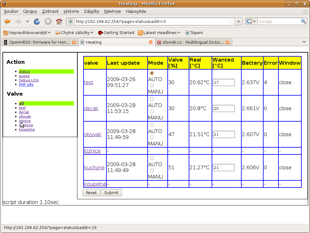
Wireless aplication screenshot (false window close detection problem)
Attached files:
-
 history.png
(120 KB)
history.png
(120 KB)
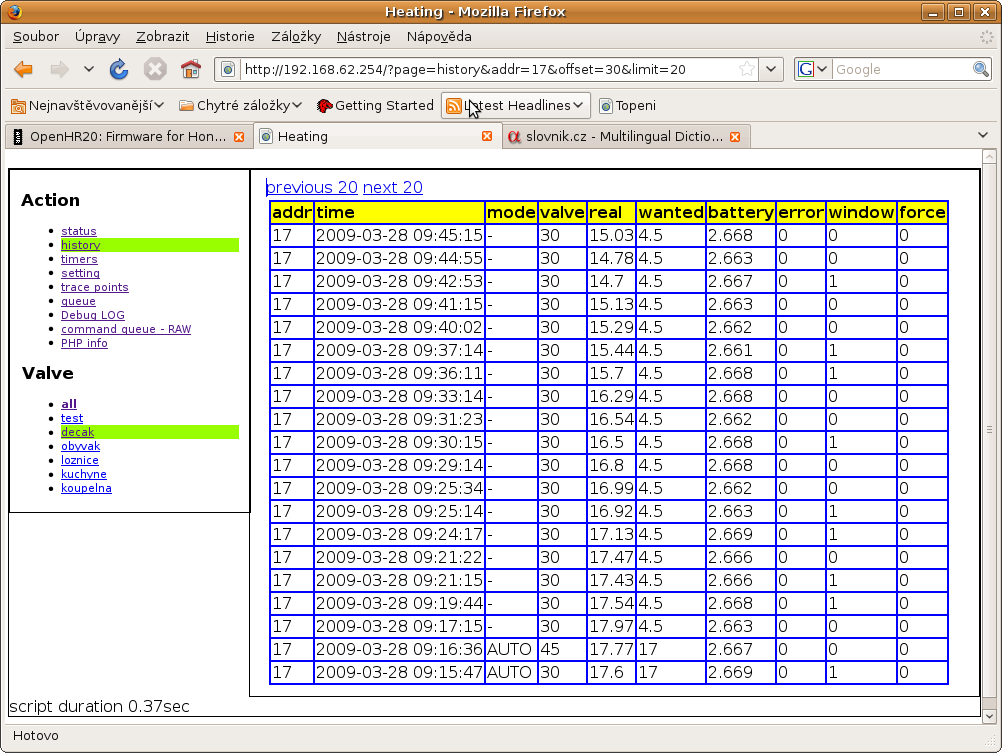
Wireless aplication screenshot #3 (timers)
Attached files:
-
 timers.png
(91 KB)
timers.png
(91 KB)
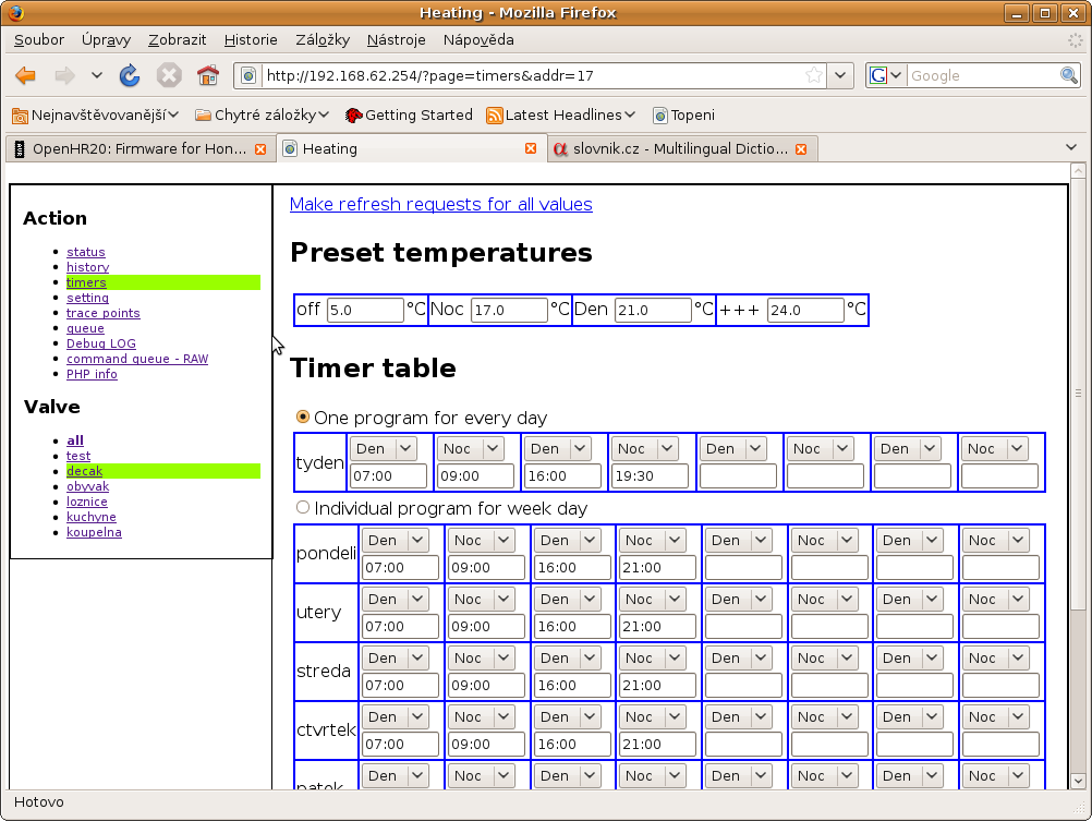
Guest
#1210054
Hello jiri,

your last inputs are very interesting. I think i have to upgrade to a
wireless version now....

I use at the moment Rev. 192 and since 3-4 days i have problems with the
time, each day the time changes with one additional hour (issue with
sommertime ?? the actual time is e.g. 10:00 but HR20 shows 11:00 ,next
day 12:00 and so on).

regards
reinis
@reinis: it look like bad XTAL. I have 6x HR20 and usual precision is
better than +-2sec/day except one (8 sec/day).
But with wireless extension it is not problem it is syncronized from
master. And master can be syncronized from internet.
Guest
#1211163
@jiri, regarding the 1 hour timeshift, i think it has something to do
with the follwing function:

void RTC_AddOneSecond    (void)

Add one second to clock variables

Note:
        * calculate overflows, regarding leapyear, etc.
        * process daylight saving
              o last sunday in march 1:59:59 -> 3:00:00
              o last sunday in october 2:59:59 -> 2:00:00
                ONLY ONE TIME -> set FLAG RTC_DS
                reset FLAG RTC_DS on November 1st

over a longer time/several weeks the time was always correct on all of
my hr20. The problem started only last week and on all of the three
hr20. I resetted the time on the next day i had again a 1 hour offset
but only until today (summertime change). This morning the 1 hour
timeshift was not there anymore and i did a manual set to summertime
(daylight saving).

regards
reinis
reinis, before Rev207 there was a bug in the daylight saving routine (see our postings on 2009-03-04). As you are using Rev192, it is very likely that you hit that problem. BR, Jörg.
@Jorg & reinis: Jorg have true. This bug was fixed and I was not abble to see that you are use too old version before bugfix. Wireles extension: New Rev 228 with graphs. I was not abble to find any library for lightweight XY grapg. All was too havy for embeded router. Therefore I was create one oprimized for this project. I will improve look&feel but you can see result from Rev 228 on attachment.
Attached files:
-
 status.png
(95 KB)
status.png
(95 KB)
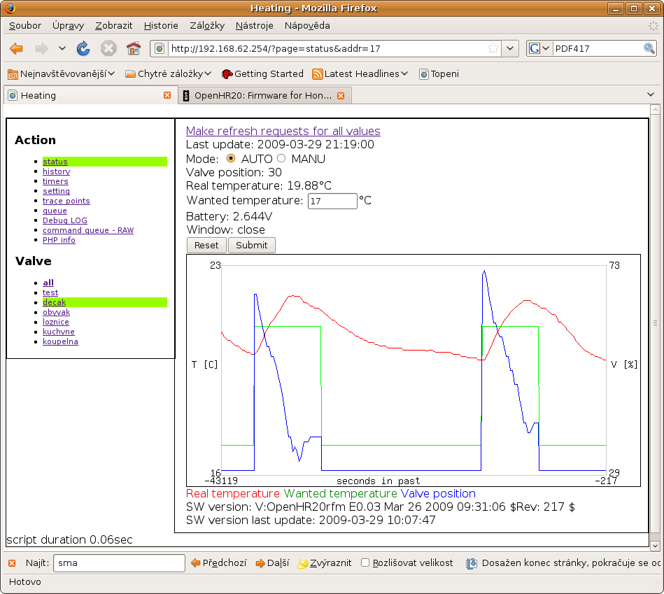
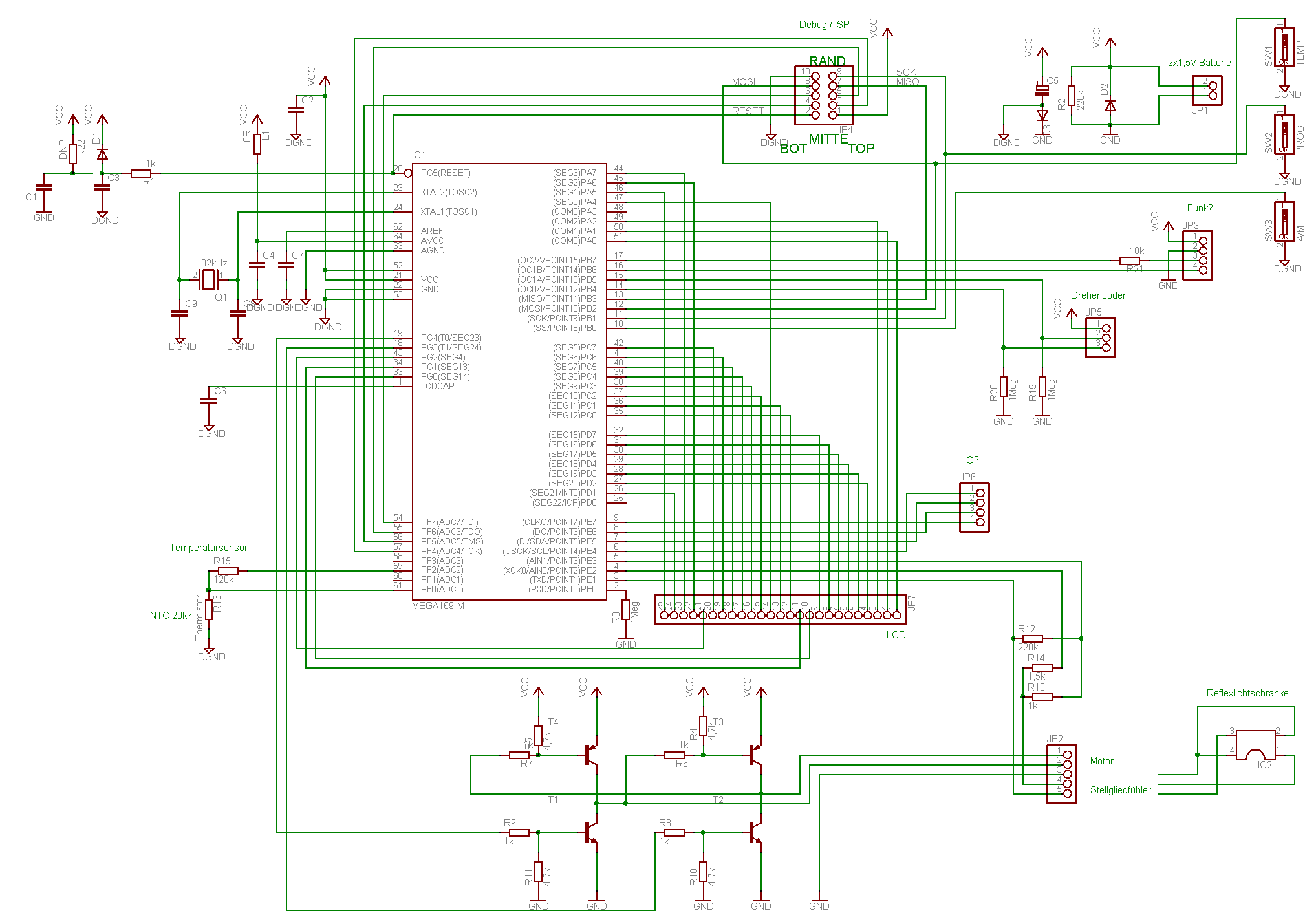

Hi Jiri, regarding the wireless version (Rev207), I have some questions: - when I compile it, I get
1 | |
is this ok?
- how does the HR20 with this version behave, if I do not have a master
running? Does it use its individual settings then? Does it send the 4
minute reports wireless instead of via RS232?
BR,
Jörg.
PS: I quite regularly (but not always!) see that the temperature reading
changes by some degrees (1.5 to 2?)while the motor is running (all
firmware revisions). Is there any explanation for this? Can this cause
any trouble? I am asking because yesterday morning the bathroom was cold
and the display showing 'OPen' without any cause. Nobody had opened the
window nor the door and half an hour earlier the temperature had been
ok. I have never managed to get this response ('Open') by really opening
the window (not even with the original firmware). In most cases when I
tried this (open window), the temperature did not fall fast enough. So
it is even more strange what I saw yesterday.
@Jörg: Please use recomended compiler WinAVR-20071221 or disable something on debug.h Q: how does the HR20 with this version behave, if I do not have a master running? A: you can use RS232 connection in same way as before this modification. But if you use only wireless and master not runnig, software will save 4 minutes report to buffer, after buffer overload (it is small for maximum 7 reports) data will be lost. Q: Does it use its individual settings then? A: yes, setting is individual for each valve. But you can manualy change AUTO/MANU mode or wanted temperature easily from one page. Q: Does it send the 4 minute reports wireless instead of via RS232? A: yes, you can see example on screenshots Jiri
Jorg: Temperature reading during motor run: You are right, motor measure too big noise for exact measure. We will must change it. But till now I was not have any accident from this, because we are use 15 second average for temperature controler. But window open detector have noise filter only from 5 values. You can try change this filter setting it is config.window_open_noise_filter setting (0x23 configuration). But I wrote request to disable measure during motor run into TODO list. Jiri
Jiri, first of all, I saw your graph from Rev228. This is very nice! - Regarding the wireless version, I want to have reports via RFM12 without using a master, e.g. for logging. Means that the HR20 works exactly as with the normal version but with wireless reports instead of RS232. Have to find out how this works. The other question was whether the wireless version will use its own (stored in the HR20!) settings, if the master fails working (or is not present at all). I understand that if the master is running, it takes full control. - Regarding the temperature measurement, I do not understand why the ADC buffer is 60 entries long and only 15 are used for the average (compile time options, not changeable during runtime). Does this make any sense? BR, Jörg. PS: I still have a lot of questions concerning the code and unfortunately not enough time to go through it and understand it in detail. I am just busy working on my remote switches with RFM12. Got first PCBs and will try getting these to work during the next time.