I need some help in my VHDL project.

I need to write code for multiplexig 7 segment displays (4 of them) to
write 4 different characters.

After, I need to turn off/turn on all 4 7 segment displays every second.
(Blinking/flashing sign with always same letters).

I've done the multiplexing and on the Nexys3 board and got my text on 4
7 segment displays, but can't figure out how to turn on/off all displays
at same time with my text.

I got some kind of error: "Can't use Anode_Active same time in 2
processes".

Did anyone have a similar problem?

I appreciate any kind of help! <3

x7seg.txt --main code is here
x7seg_top.txt --just a top module
freqDivGen --clock division
Bozidar K. wrote:
> I got some kind of error: "Can't use Anode_Active same time in 2
> processes".
> Did anyone have a similar problem?
Yes, everybody who tries to assign a value to one and the same signal
from two processes.

Have a look for "multiple drivers vhdl" to find thousands of similar
problems...

BTW: pls attach *.vhdl files, not *.txt files. You will find some magic
named syntax highlighting... ?
Attached files:
-

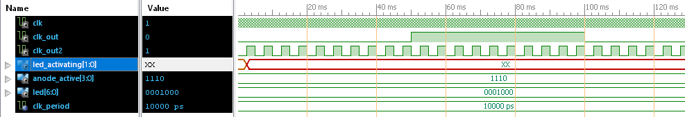
x7seg_XX_wf.PNG
12 KB -

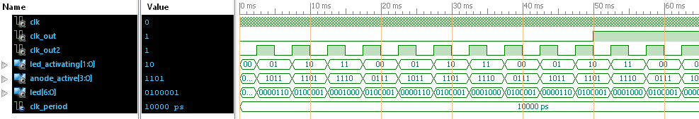
x7seg_init00_wf.PNG
13 KB
Meanwhile I had the time to peek into your code and one thing in
advance:
1 | if (temp>=nfCLK/2) then |
2 | clk_o<=not clk_o; |
This ist not the proper way to generate clocks in FPGAs. Have a look for
a strategy named "Clock Enable"...

Bozidar K. wrote:
> I got some kind of error
When I synthesize those files with Xilinx ISE I get:
1 | Process "Synthesize - XST" completed successfully |
But the simulation shows: those two frequency dividers are working, but
nothing else is going on.
A closer look turns up: the counter led_activating is XX throughout
resulting in presenting the "when others" value at the "Anode_Active"
and "LED".

Try it with initializing the counter:
1 | signal led_activating: std_logic_vector (1 downto 0) := "00"; |
Then the simulation runs like it should...
Please log in before posting. Registration is free and takes only a minute.
Existing account
Do you have a Google/GoogleMail account? No registration required!
Log in with Google account
Log in with Google account
No account? Register here.