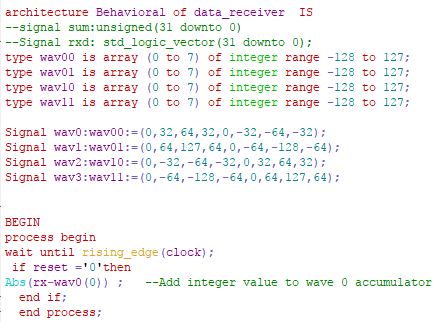
Im trying to use accumulators to check the incoming integers of
different wave forms.

I have 4 wave forms but i am sending them in as a 32 bit stream of data.
I know i would need a start point to be sure that i could decode the
message correctly but i just want to get it to work to start with.

i think i need 4 processes so i can read each integer value on the
rising clock edge concurrently and subtract it from each of my reference
integer for each of the waveforms.

I have created 4 signals with the values of each waveform,but these are
outputs so i think i need to change them to an input to be able to read
them or manipulate them?


Rx:in STD_LOGIC_VECTOR (31 downto 0)  ;
this is the incommoding bit stream

Abs(rx-wav0(0)) ;

This is taking the input value and subtracting it from bit 0 of wav0.
if i put an output <= before this code it will equal the difference of
the operation.
but how do i do this for 8 samples so i can work out what wave is
transmitting.
im having problems in how i hold the data after each cycle.
I want to see over eight cycles which wave has the lowest variance,this
will determine the correct waveform.
Attached files:
-

Capture.JPG
41 KB
Richard T. wrote:
> i think i need 4 processes
I think you are substantially wrong. It seems you try to use VHDL as a
programming language. Instead you must think in hardware and DESCRIBE
this hardware (the D in VHDL).

In your screenshots you need only one array type definition. Then you
instantiate four of those arrays of that type.

But it would be much more convenient when you attach a VHDL file instead
of a screenshot. Then it would be easy to copy and edit your code. Got
the trick?
i agree i keep approaching this as some c program to manipulate the
design,i know VDHL is a hardware language and shows how different
physical properties connect  together. three entity's have inputs and
outputs and wires connecting them together.

but also if i want to send Data and then revive data while carrying out
mathematical operations before giving a system response ,isn't this more
like programing the functionality of this system?

how do i text wrap from modlesim neatly onto the forum,is there a
function in modlesim.i cant see a function.

yes the reason why i set four arrays of different values is because i
wanted to use them as a kind of constant that i could compare the
incoming integer against and give me a value.

each value could the be added to the sum of eight bits,the lowest value
would show me the wave that was being transmitted.

but i don't know how both to set up a constant in the architecture ,i
thought you could set it up in a process but it didn't really seem to
work.

i think if i had 8 processes looking at bit 0,1,2,3,4,5,6,7 of a
constant separately,on a rising clock edge after 8 cycles i could read a
complete waveform.
Richard T. wrote:
> the reason why i set four arrays of different values is because...
You did not only set up four arrays. You invoked four new data
types. One data type for those four arrays would be enough.

Richard T. wrote:
> how do i text wrap from modlesim neatly onto the forum,is there a
> function in modlesim.i cant see a function.
Attach a VHDL file, not a text file. Eg  rx.vhd or rx.vhdl instead
rx.txt. Or read those few lines named "Formatting Options"  above each
editbox...

What information is in the
Rx:in STD_LOGIC_VECTOR (31 downto 0)?
And what should happen to that information?
Hi

i have changed my receiver code to make four accumulators that receive a
32 bit integer array rxd.

each time a bit of the array arrives i want each accumulator to be able
to minus that value from a known value and to add this value up for 8
bits of data until all four accumulators have different values.

e.g

incoming data 0,-3,-6,-3,0,3,6,3
1 | accumulator 1 sum0<=abs(rxd-wav1(0)); |
2 | accumulator 2 sum1<=abs(rxd-wav2(0)); |
3 | accumulator 3 sum2<=abs(rxd-wav3(0)); |
4 | accumulator 4 sum3<=abs(rxd-wav4(0)); |
if wav2 had this as the constant data etc then after 8 cycles it should
=0
the others will have different values indicating wav2 was transmitting.

wav1 must be in the form of a look up table i guess so it can use the
values.
but i don't know if this could be a constant in the process?

I might need to make sum larger than 7 downto 0 to make sure i get 8
values

This is what i am trying to do

i have commented lines out as i would like to get it to actually work.

i need to create a table so i can compare what comes in against it.
i also don't understand how to form the sum correctly and how to
increment each bit of data.e.g 5th clock cycle i need to -wav1(5).
Lothar M. wrote:
> Attach a VHDL file, not a text file.
You got it. Nearly...
Richard T. wrote:
> accumulator_1.vhd.bak
I cut off the *.bak and attached the vhd file to your post. Do you see
the difference?
And I wrapped you VHDL code with the [vhdl] tags...

Richard T. wrote:
> This is what i am trying to do
Im sorry, i do not get the trick. Absolutely not. But it seems to me you
want to do something very usual in a complicated way. Can you draw a
picture showing the data flow of you design? What information is in the
32 bit vector? And what should happen with that data?
i cant see whats inside the file

I have gone back to the drawing board once again

i have made a code generator 4 outputs all generating different  8 bit
integer arrays

then they enter a mux which then selects which array is transmitted out
of the dataout : out

this all works ok

now i which to capture the output by connecting it to an input in a
different entity.

This entity takes a bit of data and using an accumulator or 4 i wish to
subtract the incoming integer from my known 8 bit array one at a time
each clock cycle and sum the absolute vale up for each of my 4 possible
8 bit arrays.the lowest value will indicate the transmitted wave.

I have attached my data flow my crayons ran out so i put it in word
Attached files:
-

linesandrectangles.PNG
5.3 KB

rich_t wrote:
> dataflow.docx
*.docx is (beside the virus story) not a good and portable format
because my smartphone can't handle it.
*.pdf is much better.
And a simple screenshot IN *.PNG FORMAT would be excellent.

> This entity takes a bit of data and using an accumulator or 4 i wish to
> subtract the incoming integer from my known 8 bit array one at a time
> each clock cycle and sum the absolute vale up for each of my 4 possible
> 8 bit arrays.
????

> I have gone back to the drawing board once again
Can you write your signals and ports to that sketch? What should happen
inside the empty rectangles? Do those rectangles have a function or
names?
Please log in before posting. Registration is free and takes only a minute.
Existing account
Do you have a Google/GoogleMail account? No registration required!
Log in with Google account
Log in with Google account
No account? Register here.