-
Thread
multiple driver error
if (clk'event and clk='1') then if (en = '1' and rd='1' and wr='1' and s2='1' and count1="111" and s1='0' ) then ... [/vhdl] Due to the incomplete sensitivity list your simnulation ist totally crap. And the description of an asynchronous clock enable is very unusual... :-/ This warning
-
Thread
Error in VHDL
when "00100000"=> y<="101"; when "01000000"=> y<="110"; when others=> y<="111"; end case; else y<="UUU"; end if; end process; end enc_arc; [/vhdl] this is my code but i get this error message
-
Thread
Bit Bang SPI
SD card. How can I bit bang SPI on ARM? I couldn't find SPI bit bang code specifically for ARM/LPC111x. It is simply using bit bang code for AVR/8051/etc? Thanks in advance, John
-
Article
Augendiagramm
I2S-Datensignals aufgenommen mit einem FPGA-basierten DIY-Tester unter Nutzung eines 6-Bit-Musters (000.000 -> 111.111) = 64 Kombinationen und 4 überlagerten Durchläufen. Nutzfrequenz 49152 MHz (768 kHz Audio), Abtastung x 4, Plattform: Terrasic DE-115 mit Cyclone IV-FPGA. Am Ende der Leitung ist das Auge noch gerade
-
Thread
RAM overflow is it acceptable
: 32801 from 26624 -------> 123% Number of 4 input LUTs : 29767 from 26624 -------> 111% Number of bonded IOBs : 33 from 221 -------> 14% Number of GCLKs : 2 from 8 ------->25% ------------------------------------------------------------
-
Thread
Instruction set implementation in VHDL
constant BEQ : std_logic_vector(2 downto 0) := "110"; constant JALR : std_logic_vector(2 downto 0) := "111"; -- SIGNALS DECLARATION signal opcode : std_logic_vector(MAXWIDTH-1 downto MAXWIDTH-3); signal regA : std_logic_vector(MAXWIDTH-4 downto MAXWIDTH-6); signal regB : std_logic_vector(MAXWIDTH
-
Thread
Header for PIC16F688 with C-Compiler
digital pin. I don't see it on this chip. As for the configuration bits (what is set in MPLAB, page 111 of datasheet), make sure the watchdog is disabled for now, WDTE, and set FOSC to binary 100. That sets it to use the internal oscillator. Make sure the MCLR pin is pulled to +5 so it doesn't get stuck
-
Thread
need help to modify my code
data = 8'b11100011; 7'b101: data = 8'b00110011; 7'b110: data = 8'b11110111; 7'b111: data = 8'b00111011; 7'b1000: data = 8'b00110001; 7'b1001: data = 8'b00010000; 7'b1010: data = 8'b00100000; 7'b1011: data = 8'b11101101; 7'b1100: data = 8'
= 8'b11110011; 7'b101: weight = 8'b11100110; 7'b110: weight = 8'b11101100; 7'b111: weight = 8'b11110110; 7'b1000: weight = 8'b11111001; 7'b1001: weight = 8'b00000010; 7'b1010: weight = 8'b11111011; 7'b1011: weight = 8'b00001100; 7'b1100:
-
Thread
M-Bus via Raspberry: reading out ABB B23 meter
my German post which I unfortunately cannot edit anymore. I need to read data from an ABB "B23 111-101" meter which is accessible via an IR-interface on its left side. This IR-interface is configured to M-Bus, 2400 Bd & Address 9 (arbitrary number). For reading from that IF I am using an IR Read
-
Thread
Resetting Registers on Digital Clock Manager Output
reg [3 : 0] SR; always @ (posedge CLKIN) begin if(RESET) begin SR [3 : 0] <= 4'b111; LOCKED_R <=0; end else begin LOCKED_R <= LOCKED; if(LOCKED < LOCKED_R | STATUS [1] )// H to L LOCKED | CLKIN UNSTABLE SR <= {1'b1 , SR[3 : 1]}; else SR <= {1'b0 , SR[
-
Thread
problems with the at91sam7xc getting started example
..\lowlevel.c:102: error: `AT91C_PMC_MOSCS' undeclared (first use in this function) ..\lowlevel.c:111: error: `AT91C_CKGR_USBDIV_1' undeclared (first use in this function) ..\lowlevel.c:112: error: `AT91C_CKGR_OUT_0' undeclared (first use in this function) ..\lowlevel.c:114: error: `AT91C_CKGR_MUL'
-
Thread
problem with sinulation in ISE (FPGA)
VHDL coding itself in each entity. The PN generator for Source 1 is initialized with (S2 S1 S0) = 111 and generates PN code 1110100 whereas the PN generator for Source 2 is initialized with (S2 S1 S0) = 110 and generates PN code1101001. so I wrote the sketch I create two inputs one is( CLOCK )
-
Thread
How to do this please
to bus a The return_out output will only be modified when change has a value different from 3'b111. If change is equal to 3'b100, then the return_out output will be equal to the bus formed by the least significant bits of a and b. If change is equal to 3'b001, then the return_out output will
-
Thread
does vhdl accept this assignment of bits
first_part[/vhdl] contains the copied bits from the stream, signal flag contain the actual no bits, either 111 for 001 or 11 for 01 and [vhdl]signal second_part[/vhdl] contains the final inverted form. Here, i want to ask that if the do the following, would it achieve my purpose without error: [vhdl] first_part
-
Article
Diskussion:Hausbus
Hallo, In dem Artikel wird man gleich ins kalte Wasser geworfen. Was ist ein "Hausbus"? -- 84.132.111.35 02:26, 24. Jul 2006 (CEST)
-
Thread
Weird warning for my design
SCORE_Inter <= DelIy_i_j_1; //C 3'b110: SCORE_Inter <= LUT; //A 3'b111: SCORE_Inter <= 0; //- (output 0) default: SCORE_Inter <= 0; //- (output 0) endcase end endmodule [/code] Based on the attached waveform,the 1st
-
Thread
Datapath 8 bits VHDL Modelsim
when "101" => f <= a - b; -- substact when "110" => f <= a + 1; -- increment when "111" => f <= a - 1; -- decrement when others => f <= (others => '0'); end case; end process; end behavior; -- shifter .vhd library ieee ; use ieee.std_logic_1164.all ; entity
-
Thread
VHDL simulation problem-need experts review
; led<="110"; if(bi < 7) then bi:=bi+1; end if; elsif(cyc=20 ) then ack<=sda; bi:=0; led<="111"; elsif (cyc>=21 and cyc<=28 ) then sda<=data(2)(bi); led<="000"; if(bi < 7) then bi:=bi+1; end if; elsif(cyc=29 ) then ack<=sda; led<="001"; elsif(cyc=30 and count >70) then sda<='1'; led
-
Thread
compilation error
Error: ex4.vhd(89): Nonresolved signal 'sel_mux' has multiple sources. # Drivers: # ex4.vhd(111):Statement MUX_DFF # ex4.vhd(96):Conditional signal assignment line__96 # ** Error: ex4.vhd(139): VHDL Compiler exiting # D:/Modeltech_pe_edu_10.2a/win32pe_edu/vcom failed. thanks in advance
-
Thread
ADC on DEO NANO not working
rising_edge(CLK_50); rst_btn_sr <= rst_btn_sr(1 downto 0) & (NOT BTN_RST); if (rst_btn_sr = "111") then reset_me <= '1'; else reset_me <= '0'; end if; end process reset_btn_proc; --RESET process reset_proc :process begin wait until rising_edge(CLK
-
Thread
Verilog buffer implementation problem
<= 4'b0; FSM_read_state <= ADC_Channel; ADC_CH <= 3'b111; // invalid channel channel_changed <= 1'b0; ch_cng_cnt <= 0; end else begin case(FSM_read_state) ADC_Channel: begin
-
Thread
vhdl code simulation
"101", not alu_arm1 when "110", not alu_arm2 when "111", "--------" when others; end behavioral; ----------------------------------------------------------------------- library ieee; use ieee.std_logic_1164.all; use ieee.std_logic_unsigned.all
-
Article
RFM12
(:8) 010 = 1, 6 MHz (:6) 011 = 2 MHz (:5) 100 = 2,5 MHz (:4) 101 = 3, 3 MHz (:3) 110 = 5 MHz (:2) 111 = 10 MHz rowspan=3|v rowspan=3|voltage rowspan=3|Bestimmt die Betriebsspannung, bei der der RFM12 einen Unterspannungs-Interrupt auslöst. Im Power-Managment muss das eb-Bit aktiv sein, damit dies funktioniert
000 = reserviert 001 = 400 kHz 010 = 340 kHz 011 = 270 kHz 100 = 200 kHz 101 =134 kHz 110 = 67 kHz 111 = reserviert rowspan=4|g rowspan=4|lna gain select rowspan=4|Verstärkungsfaktor des UHF-Verstärkers am Eingang (LNA = Low Noise Amplifier, als ob das nicht selbstverständlich ist). Werte in dBm (Dezibel
-
Thread
Can't assign value in the register
output reg [2:0]S; always @(posedge CLK) begin if(Resetn == 0) S <= 3'b111; else begin if (Enable == 1) S <= S + 1; end end endmodule module Regn(R, Rin, CLK, Q); input [7:0]R; input Rin, CLK; output reg [7:0]Q;
-
 Image
Image
Software-Screenshot einer Terminal-Anwendung mit Datenliste
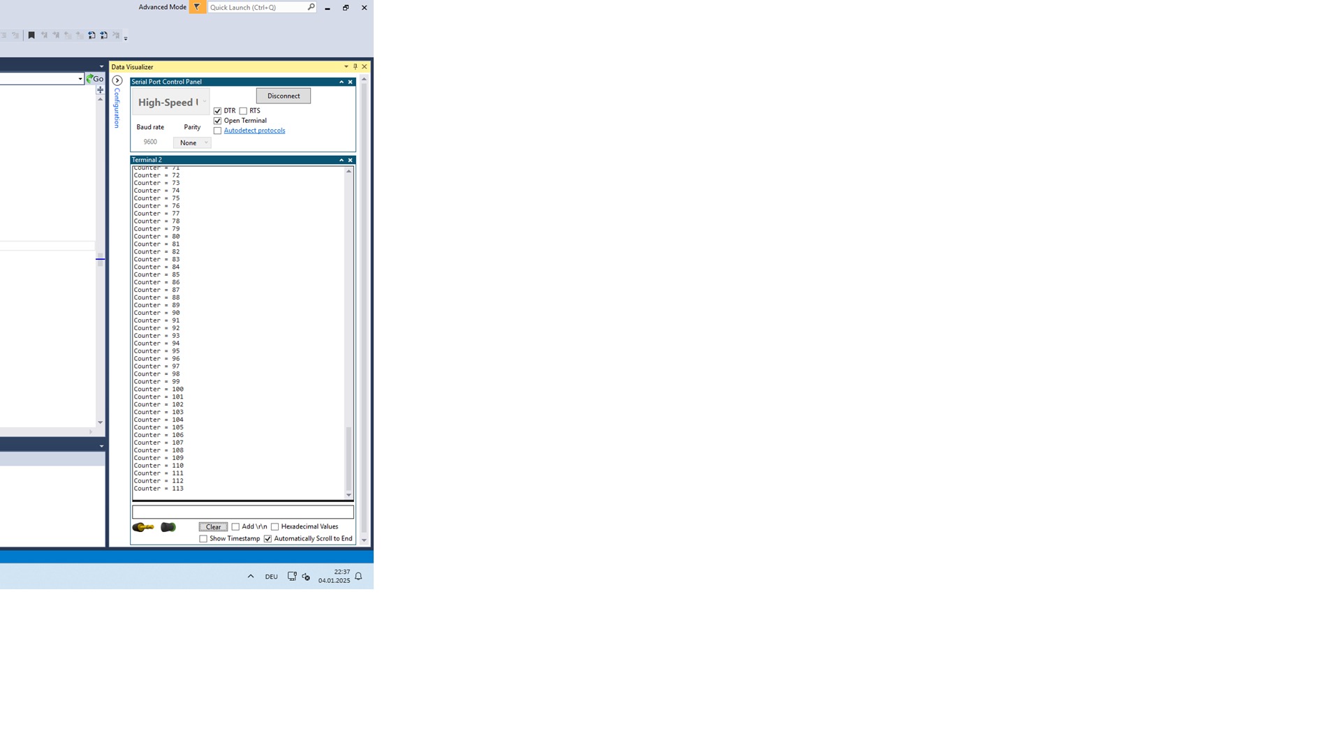
Counter = 91 Counter = 94 Counter = 97 Counter = 100 Counter = 102 Counter = 105 Counter = 108 Counter = 111 Counter = 115 Clear Add Hexadecimal Values Show Timestamp Automatically Scroll to End DEU 04.01.2025
-
 Image
Image
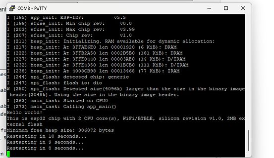
PuTTY Terminal Ausgabe ESP-IDF Bootvorgang
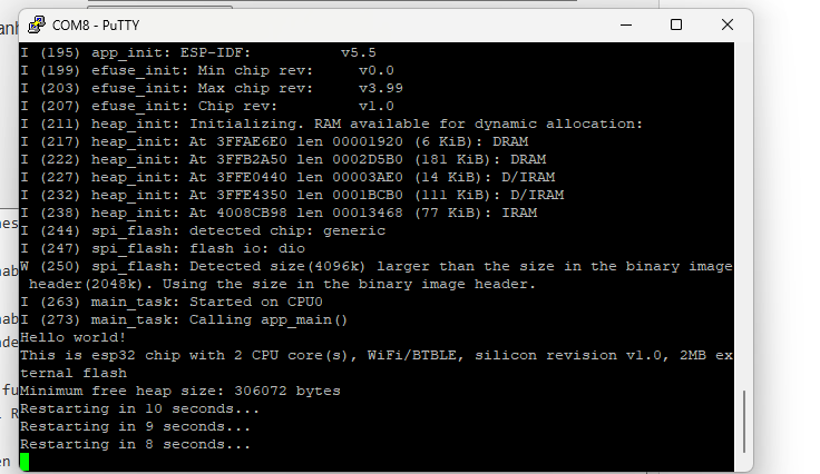
heap_init: At 3FFE0440 len 00003AE0 (14 KiB): D/IRAM I (232) heap_init: At 3FFE4350 len 0001BCB0 (111 KiB): D/IRAM I (238) heap_init: At 4008CB98 len 00013468 (77 KiB): IRAM I (244) spi_flash: detected chip: generic I (247) spi_flash: flash io: dio I (250) spi_flash: Detected size (4096k) larger than
-
 Image
Image
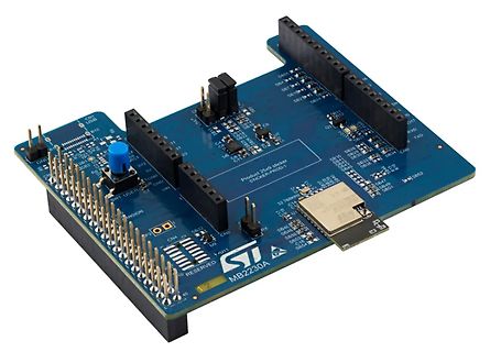
ST MB2230A Erweiterungsplatine
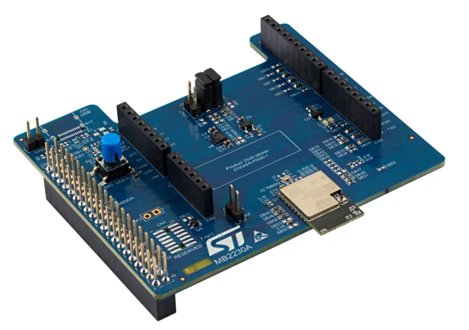
SB94 SB95 SB96 SB97 SB98 SB99 SB100 SB101 SB102 SB103 SB104 SB105 SB106 SB107 SB108 SB109 SB110 SB111 SB112 SB113 SB114 SB115 SB116 SB117 SB118 SB119 SB120 SB121 SB122 SB123 SB124 SB125 SB126 SB127 SB128 SB129 SB130 SB131 SB132 SB133 SB134 SB135 SB136 SB137 SB138 SB139 SB140 SB141 SB142 SB143 SB144
-
Article
Ethernet-Controller
sind aber ggf. auch als reiner Ethernet-MAC-Controller nutzbar. ( Bezugsquelle z. B.: oder SMSC LAN91C111/LAN911x/LAN921x; 10/100 MAC+PHY ASIX AX88796B; 10/100 MAC+PHY; NE2000- & RTL8019-kompatibel ASIX AX88180 10/100/1000 Ethernet MAC µC mit Ethernet-Interface. Atmel AT91SAM7X256 Atmel AT91SAMSAM9260 /
-
Article
Zahlensysteme
sich bequem durch Angabe einer Oktalzahl einstellen lassen (z. B. entspricht "751" dem Bitmuster "111 101 001" oder "rwxr-x--x" in der üblichen Zugriffsrecht-Darstellung.) . Umrechnung. Viele Taschenrechner können die Zahlensysteme umrechnen, so auch der Windows-Taschenrechner oder der UNIX-Taschenrechner