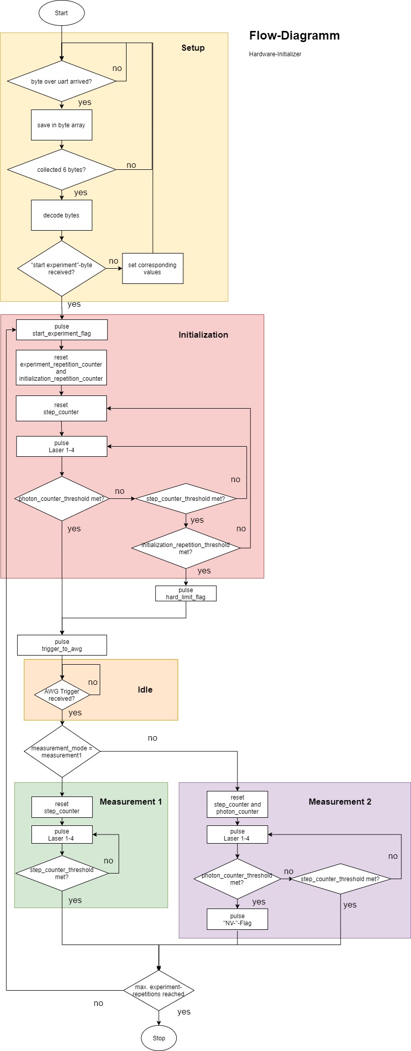
Hey everyone

I need to design a system which counts photons and pulses lasers for an
experiment that requires a clock speed of at least 80 MHz.

The system should be able to be setup using UART-communication.

The experiment can be in either an "initialization"-phase, an
"idle"-phase or a "measurement"-phase.

When the experiment start, the "initialization"-phase is entered. The
"initialization"-phase ends when a desired amount of photons are counted
during a specified time or if the desired amount photons are not
counted, which leads to repeating the "initialization"-phase. If the
"initialization"-phase has already been repeated for a max. amount of
times, the "initialization"-phase is also left.
When the "initialization"-phase is left, the system sends a
trigger-pulse to another device (arbitrary waveform generator, short
"awg").
During the next phase, namely the "idle"-phase, the system waits for a
returning pulse from the "awg". When it is received, the system moves on
to the measurement-phase.
There are two different ways of measuring. "Measurement 1" ends after a
specified time. "Measurement 2" ends after either a specified time or
after a certain amount of photons are counted.
After the "measurement"-phase, the experiment is either repeated,
meaning it goes back to the "initialization"-phase, or, if the maximum
amount of repetitions is reached, back into the "step"-phase.
Lasers are pulsed during the "initialization" and "measurement"-phase.
For this reason, a counter is used, which is incremented at every
clock-cycle, called "step-counter". The step-counter is reset at the
beginning of the "initialization"- and "measurement"-phase and is used
for timing laser-pulses and the window during which photons are counted.
The laser-pulses and the photon-counting-window possess a starting-point
(offset) and a length. The pulse/window starts when the step-counter is
equal to the offset and lasts till the step-counter-value is larger than
the offset and the length of the pulse/window added together.
(See flow diagram)
The Lasers should be able to be pulsed twice during a phase.


I/O

The following inputs are used:
"rx_serial" (uart rx for communication),
"trigger_from_awg",
"trigger_from_apd" (avalanche photo diode)
The inputs are synchronized using two flip-flops.
The following outputs are used:
  "flag_start_experiment",
  "flag_hard_limi",
  "flag_nv_minus",
  "trigger_awg",
  "pulse_laser_1",
  "pulse_laser_2",
"pulse_laser_3",
"pulse_laser_4",
Further outputs that are pulsed like the lasers


UART-communication

The system reads in bytes into an array of bytes until 6 bytes have been
collected within a defined amount of time. If less bytes arrive during
that time, all bytes are discarded. The bytes that arrived are decoded
and either settings are set or the experiment is started.


What I have so far

I'm using Lattice Diamond (3.11.0.396.3) and the Lattice MachOX3F
Starterkit.
I created a design using a moore-state-machine which works during
simulation but partially fails when synthesized (the bytes sent over
uart are read in, "decoded" and the values are set correctly but the
system does not trigger the outputs when the experiment is started and
the "initialization"-phase is never exited). Also, I am only able to
synthesize the design without timing issues when run at 53.2 MHz.
I wrote the following modules:

  state_machine https://paste.ofcode.org/NGxVLNcJ93pYb7FsHV2He6
(contains the sate machine, there are intermediate state between
experiment-phases which pulse the outputs and reset the counters)

  counter https://paste.ofcode.org/TwdUBaFZau53gfYVvqZLMm (has a
threshold-value which an increment, clear and pulse_output input.
pulse_output determines if the threshold_reached output is only toggled
or pulsed)

  multiplexer_counter_state
https://paste.ofcode.org/uLw3Pfw7GTnxux3SNcTPUb (has two integer input
and the current state to determine the output, used to set the desired
counter-value for the different states, e.g. amount of photon during
initialization and measurement)

  pulser_solo https://pastebin.com/c2GuA1sJ (has current_step as input,
the desired offset in respect the the current_step and the pulse length,
used for timing the photon-count-window)

  pulser_duo https://paste.ofcode.org/7nzwqhRCLfQ2XSUabwtjPG (contains
two pulser_solo and has therefore two offset and to length inputs, used
to time the lasers, which can be used twice in one phase)

  multiplexer_pulser_solo_state https://pastebin.com/Q2KQp0Ha (same as
multiplexer_counter_state but but for offset and length used for the
pulser_solo-module)

  multiplexer_pulser_duo_sate https://pastebin.com/xvRRKcVA (same twice
multiplexer_pulser_solo_state)

  experiment_module https://pastebin.com/dqzpi6jq (contains the
state_machine, all counters, all pulsers and all their multiplexers)

  uart_receiver https://pastebin.com/Ww1bUvyi (creates byte from uart
stream, contains uart-signal synchronizing)

  uart_byte_collector https://pastebin.com/JqJPM0hZ (collects 6 bytes
from uart_receiver and outputs them when all are collected)

  uart_interface https://pastebin.com/MNqyWmHR (contains uart_receiver
and uart_byte_collector)

  uart_interpreter https://pastebin.com/M8rW6imz (decodes the 6 bytes
coming collected from the uart_byte_collector)

  tiptop_module https://pastebin.com/2g1V9YqG (contains the
uart_interface, the unart_interpreter and the experiment_module)

  top_module https://pastebin.com/mhkqMKjW (contains the tiptop_module,
the synchronizing of the two trigger inputs and clock and reset setting
for the particular lattice-device)

This is my first "larger" design and I am sure the code is not as
efficient as it can be, as the task does not seem to be extremely
complex, but still limits the max clock-speed to 53.3MHz from the
potential 133MHz.

I therefore wanted to ask for some feedback regarding the general design
choices and if someone spots a construct which limits the clock-speed.

I can post screenshots of the synthesize-strategy if needed.

Thanks a lot
Attached files:
-

flow-diagramm.jpg
150 KB
Define proper timing constraints and the synthesis tool tell you the
critical path.

Duke
Lu F. wrote:
> I created a design using a moore-state-machine which works during
> simulation but partially fails when synthesized
Sounds like a timing violation. Hopefully you sync in those obviously
async trigger_from_xxx signals somewhere before using them in a FSM.

> Also, I am only able to synthesize the design without timing issues when
> run at 53.2 MHz.
What clock frequency uses your hardware?
Do you run that 53MHz design with 80MHz?
I spotted lots of comparators in the code. What size are these?

Lu F. wrote:
> I wrote the following modules:
Instead of using an external server attach those design files as a zip
file.
Comparators are often expensive things as Lothar pointed out already.
But often they can be optimized. For example in your counter.vhd, the
code
1 | elsif counter_value_internal < threshold and counter_value_internal < max_counter_value then |
2 | if increment = '1' then |
3 | counter_value_internal <= counter_value_internal + 1; |
4 | end if; |
could be rewritten as
1 | elsif counter_value_internal /= threshold then |
2 | if increment = '1' then |
3 | counter_value_internal <= counter_value_internal + 1; |
4 | end if; |
A comparison on a fixed value normally has a shorter critical path than
a '<'. As far as I can see, this substitution is possible in this case
(counter starts at 0, counter increments by 1, counter increments only
here, threshold is always <= max_counter_value).

Maybe the synthesis tool is smart enough to detect things like this by
itself, but often they dont.
Please log in before posting. Registration is free and takes only a minute.
Existing account
Do you have a Google/GoogleMail account? No registration required!
Log in with Google account
Log in with Google account
No account? Register here.