Good morning all !!

I allow myself to turn to you today after several to seek the solutions
without success.

Indeed I am in a rather material project where it is necessary to set up
a dating device using a CPLD card.

One of the functions to perform is the description of an SPI. It is a
question of describing the SPI in such a way that we can have 4 states
at the output (00, 01, 10 and 11) and this according to two inputs which
are the CS and the CLOCK. For this, I use verilog as language.

The problem is that I cannot evaluate this condition "end else if
(CS_SPI == 1'b1 && i == 1'b0) begin
next_state = Trans_DataBit;
Count_Bit <= 4'b1100;
assign j = i;
end
in order to access the fourth state which would allow me to count down
the 12 bits of data to be transmitted.
I enclose the description and the timing diagram where I forced the
entries.

Thank you all in advance.
I have attached files for more details.
Attached files:
-

Chronogramme_2.PNG
27 KB
One of the problems is that you are changing >> Count_Bit << in two
separated always blocks, the simulator is kind of dead-locking.
Changing a register using blocking and non-blocking assignments is bad
because it doesn't synthesize : you have like "two drivers" for the same
signal, to put it simple.
1 | always @(state or CS_SPI) |
2 | begin : MEF_SPI |
3 | next_state = 4'b0001; |
4 | |
5 | |
6 | //Count_Bit <=4'b0011; |
7 | //Count_DateBit <= 2'b11; |
8 | //Count_DataBit <= 4'b1111; |
9 | |
10 | case(state) |
11 | ... |
12 | Trans_FlagBit : if(CS_SPI == 1'b1) begin |
13 | next_state = Trans_DateBit; |
14 | Count_Bit =4'b0011; |
15 | //i = 0; |
16 | //i=3; |
17 | //SPI_Select = 1; |
18 | end |
19 | |
20 | |
21 | Trans_DateBit : if(CS_SPI == 1'b1 && i!= 1'b0 ) begin |
22 | next_state = Trans_DateBit; |
23 | Count_Bit =4'b0011; |
1 | always @ (posedge CLK_SPI) |
2 | begin : Sorie_Logiq |
3 | if (reset == 1'b1) begin |
4 | SPI_Select <= #1 2'b11; |
5 | end |
6 | else begin |
7 | case(state) |
8 | ... |
9 | Trans_DateBit : begin |
10 | SPI_Select <= #1 2'b01; |
11 | Count_Bit <= Count_Bit -1; |
12 | if(Count_Bit == 4'b0) begin |
13 | i=0; |
14 | end |
15 | //Count_Bit <=4'b0011; |
Attached files:
-

Chronogramme_3.PNG
26 KB
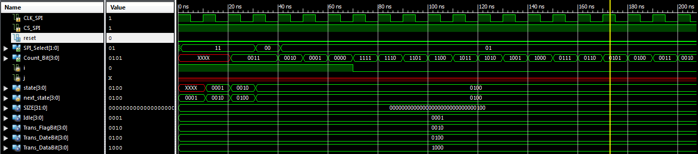
Thank you Von Ale for your answer.

I have fixed that problem but I still have some.


1 ) One of them is that I have a delay at the begining of the
SPI_Select. And that consequence of that delay is that the output is not
corresponding with the state anymore.

2 ) The other one is that I am not suppose to have 1111 after 0000 when
counting but I am having it and I don't really understang why.

I have attached the result of simulation and the description.
1 | `timescale 1ns / 1ps |
2 | ////////////////////////////////////////////////////////////////////////////////// |
3 | // Company: |
4 | // Engineer: |
5 | // |
6 | // Create Date: 17:16:35 12/27/2019 |
7 | // Design Name: |
8 | // Module Name: Projet_Tech_SPI |
9 | // Project Name: |
10 | // Target Devices: |
11 | // Tool versions: |
12 | // Description: |
13 | // |
14 | // Dependencies: |
15 | // |
16 | // Revision: |
17 | // Revision 0.01 - File Created |
18 | // Additional Comments: |
19 | // |
20 | ////////////////////////////////////////////////////////////////////////////////// |
21 | module Projet_Tech_SPI( |
22 | CLK_SPI, |
23 | CS_SPI, |
24 | reset, |
25 | Count_Bit, |
26 | //Count_DateBit, |
27 | //Count_DataBit, |
28 | SPI_Select |
29 | ); |
30 | |
31 | //------------- Déclaration des entrées ----------------------------- |
32 | input CLK_SPI, CS_SPI, reset; |
33 | //------------- Déclaration des sorties ---------------------------- |
34 | output [1:0] SPI_Select; |
35 | output [3:0] Count_Bit; |
36 | |
37 | //output [1:0] Count_DateBit; |
38 | //output [3:0] Count_DataBit; |
39 | |
40 | //------------- Les ports d'entrées ------------------- |
41 | wire CLK_SPI, CS_SPI, reset; |
42 | //------------- Les ports de sorties ------------------ |
43 | reg [1:0] SPI_Select; |
44 | reg [3:0] Count_Bit; |
45 | reg i=1'b1; |
46 | //reg [1:0] Count_DateBit; |
47 | //reg [3:0] Count_DataBit; |
48 | |
49 | //------------- Les constantes internes --------------------------- |
50 | //assign CS_SPI = i; |
51 | parameter SIZE = 4; |
52 | parameter Idle = 4'b0001, Trans_FlagBit = 4'b0010, Trans_DateBit = 4'b0100, Trans_DataBit = 4'b1000 ; |
53 | |
54 | //-------------Variables internes--------------------------- |
55 | reg [SIZE-1:0] state ;// Seq part of the FSM |
56 | reg [SIZE-1:0] next_state ;// combo part of FSM |
57 | //----------Code startes Here------------------------ |
58 | //assign next_state = fsm_function(state, Idle, Trans_FlagBit, Trans_DateBit, Trans_DataBit); |
59 | |
60 | |
61 | //---------- Logique séquentielle ----------------------------- |
62 | always @ (posedge CLK_SPI) |
63 | begin : MEF_Seq |
64 | if (reset == 1'b1) begin |
65 | state <= #1 Idle; |
66 | end else begin |
67 | state <= #1 next_state; |
68 | end |
69 | end |
70 | //---------- Fin logique séquentielle ----------------------------- |
71 | |
72 | always @(state or next_state or CS_SPI or i ) |
73 | begin : MEF_SPI |
74 | //next_state = 4'b0001; |
75 | |
76 | |
77 | //Count_Bit <=4'b0011; |
78 | //Count_DateBit <= 2'b11; |
79 | //Count_DataBit <= 4'b1111; |
80 | |
81 | case(state) |
82 | Idle : if(CS_SPI == 1'b0) begin |
83 | next_state = Idle; |
84 | end else if (CS_SPI == 1'b1) begin |
85 | next_state = Trans_FlagBit; |
86 | end |
87 | |
88 | Trans_FlagBit : if(CS_SPI == 1'b1) begin |
89 | next_state = Trans_DateBit; |
90 | //Count_Bit =4'b0011; |
91 | end |
92 | |
93 | Trans_DateBit : if((CS_SPI == 1'b1) && (i!= 1'b0) ) begin |
94 | Count_Bit =4'b0010; |
95 | next_state = Trans_DateBit; |
96 | |
97 | end else if((CS_SPI == 1'b1) && (i==1'b0) ) begin |
98 | next_state = Trans_DataBit; |
99 | //Count_Bit <=4'b1100; |
100 | i=1'b1; |
101 | end |
102 | |
103 | Trans_DataBit : if((CS_SPI == 1) && (i != 1'b0)) begin |
104 | Count_Bit <=4'b1011; |
105 | next_state = Trans_DataBit ; |
106 | end else if((CS_SPI == 1) && (i == 1'b0)) begin |
107 | next_state = Trans_FlagBit; |
108 | i=1'b1; |
109 | |
110 | //SPI_Select = 0; |
111 | end |
112 | |
113 | default : next_state = Idle; |
114 | |
115 | endcase; |
116 | end |
117 | |
118 | |
119 | |
120 | |
121 | //---------- La logique de sortie ----------------------------- |
122 | always @ (posedge CLK_SPI) |
123 | begin : Sorie_Logiq |
124 | /*if (reset == 1'b1) begin |
125 | SPI_Select <= #1 2'b11; |
126 | end |
127 | else begin*/ |
128 | case(state) |
129 | Idle : begin |
130 | SPI_Select <= 2'b11; |
131 | |
132 | end |
133 | Trans_FlagBit : begin |
134 | SPI_Select <= 2'b00; |
135 | //Count_Bit <=4'b0011; |
136 | |
137 | end |
138 | Trans_DateBit : begin |
139 | SPI_Select <= 2'b01; |
140 | Count_Bit <= Count_Bit -1; |
141 | if(Count_Bit == 4'b0) begin |
142 | i=1'b0; |
143 | end |
144 | //Count_Bit <=4'b0011; |
145 | |
146 | end |
147 | Trans_DataBit : begin |
148 | SPI_Select <= 2'b10; |
149 | Count_Bit <= Count_Bit -1; |
150 | if(Count_Bit == 4'b0) begin |
151 | i=1'b0; |
152 | end |
153 | //Count_Bit <=4'b1100; |
154 | |
155 | end |
156 | /*default : begin |
157 | SPI_Select <= #1 2'b11; |
158 | |
159 | end*/ |
160 | endcase |
161 | //end |
162 | end // End Of Block OUTPUT_LOGIC |
163 | |
164 | endmodule |
I will welcome any help

Thank you in advance !!
Count_Bit is still being modified in both always. Maybe you should do
one clocked always block for the state machine, instead of two.

You are using ModelSim to simulate, maybe you should try to synthesize
the code for some random FPGA, whatever you have installed, and have a
look at the errors and warnings you get. It helps with double written
registers and things like that :).
I also find that a state diagram with conditions helps during the design
phase and implementation phases, it helps you visualize what you intend
to do and to find possible misunderstandings between how you think the
problem can be solved and how you are trying to solve it :). Sometimes I
write down timing diagrams, helps too when the state machines get a bit
too complicated.
Attached files:
-

Chronogramme_4.PNG
25 KB
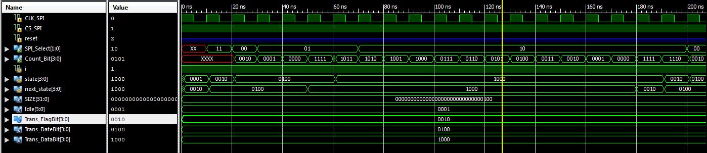
Thank you for your answer,

I have tried with a single always but it doesn't work.

I have attached the description and the result.
1 | `timescale 1ns / 1ps |
2 | ////////////////////////////////////////////////////////////////////////////////// |
3 | // Company: |
4 | // Engineer: |
5 | // |
6 | // Create Date: 17:16:35 12/27/2019 |
7 | // Design Name: |
8 | // Module Name: Projet_Tech_SPI |
9 | // Project Name: |
10 | // Target Devices: |
11 | // Tool versions: |
12 | // Description: |
13 | // |
14 | // Dependencies: |
15 | // |
16 | // Revision: |
17 | // Revision 0.01 - File Created |
18 | // Additional Comments: |
19 | // |
20 | ////////////////////////////////////////////////////////////////////////////////// |
21 | module Projet_Tech_SPI( |
22 | CLK_SPI, |
23 | CS_SPI, |
24 | reset, |
25 | Count_Bit, |
26 | //Count_DateBit, |
27 | //Count_DataBit, |
28 | SPI_Select |
29 | ); |
30 | |
31 | //------------- Déclaration des entrées ----------------------------- |
32 | input CLK_SPI, CS_SPI, reset; |
33 | //------------- Déclaration des sorties ---------------------------- |
34 | output [1:0] SPI_Select; |
35 | output [3:0] Count_Bit; |
36 | |
37 | //output [1:0] Count_DateBit; |
38 | //output [3:0] Count_DataBit; |
39 | |
40 | //------------- Les ports d'entrées ------------------- |
41 | wire CLK_SPI, CS_SPI, reset; |
42 | //------------- Les ports de sorties ------------------ |
43 | reg [1:0] SPI_Select; |
44 | reg [3:0] Count_Bit; |
45 | reg i=1'b1; |
46 | //reg [1:0] Count_DateBit; |
47 | //reg [3:0] Count_DataBit; |
48 | |
49 | //------------- Les constantes internes --------------------------- |
50 | //assign CS_SPI = i; |
51 | parameter SIZE = 4; |
52 | parameter Idle = 4'b0001, Trans_FlagBit = 4'b0010, Trans_DateBit = 4'b0100, Trans_DataBit = 4'b1000 ; |
53 | |
54 | //-------------Variables internes--------------------------- |
55 | reg [SIZE-1:0] state ;// Seq part of the FSM |
56 | reg [SIZE-1:0] next_state ;// combo part of FSM |
57 | //----------Code startes Here------------------------ |
58 | //assign next_state = fsm_function(state, Idle, Trans_FlagBit, Trans_DateBit, Trans_DataBit); |
59 | |
60 | |
61 | |
62 | always @(posedge CLK_SPI ) |
63 | begin : MEF_SPI |
64 | //next_state = 4'b0001; |
65 | |
66 | state = Idle; |
67 | //Count_Bit <=4'b0011; |
68 | //Count_DateBit <= 2'b11; |
69 | //Count_DataBit <= 4'b1111; |
70 | |
71 | case(state) |
72 | Idle : if(CS_SPI == 1'b0) begin |
73 | state = Idle; |
74 | SPI_Select = 2'b11; |
75 | end else if (CS_SPI == 1'b1) begin |
76 | state = Trans_FlagBit; |
77 | end |
78 | |
79 | Trans_FlagBit : if(CS_SPI == 1'b1) begin |
80 | SPI_Select = 2'b00; |
81 | state = Trans_DateBit; |
82 | //SPI_Select = 2'b00; |
83 | //Count_Bit =4'b0011; |
84 | end |
85 | |
86 | Trans_DateBit : if((CS_SPI == 1'b1) && (i!= 1'b0) ) begin |
87 | SPI_Select <= 2'b01; |
88 | Count_Bit =4'b0010; |
89 | Count_Bit <= Count_Bit -1; |
90 | state = Trans_DateBit; |
91 | if(Count_Bit == 4'b0) begin |
92 | i=1'b0; |
93 | end |
94 | |
95 | end else if((CS_SPI == 1'b1) && (i==1'b0) ) begin |
96 | state = Trans_DataBit; |
97 | //Count_Bit <=4'b1100; |
98 | i=1'b1; |
99 | end |
100 | |
101 | Trans_DataBit : if((CS_SPI == 1) && (i != 1'b0)) begin |
102 | SPI_Select <= 2'b01; |
103 | Count_Bit <=4'b1011; |
104 | Count_Bit <= Count_Bit -1; |
105 | state = Trans_DataBit ; |
106 | if(Count_Bit == 4'b0) begin |
107 | i=1'b0; |
108 | end |
109 | end else if((CS_SPI == 1) && (i == 1'b0)) begin |
110 | state = Trans_FlagBit; |
111 | i=1'b1; |
112 | |
113 | //SPI_Select = 0; |
114 | end |
115 | |
116 | default : next_state = Idle; |
117 | |
118 | endcase; |
119 | end |
120 | |
121 | |
122 | |
123 | endmodule |
Thank you and Happy New Year !!
You are mixing two kinds of assignments '=' and '<=' they do not mean
the same and are to be used in different kinds of assignments !.
Short description: Inside a clocked always block use '<=' only.

What I see from the simulation is that SPI_Select is not being updated,
the simulator is not understanding your code correctly.

The use of an extra flag 'i' kinds of defeats the simplicity of the
state machine you have more unneeded states, when Count_Bit is zero you
can transition.

this code is ...
1 | Count_Bit <=4'b1011; |
2 | Count_Bit <= Count_Bit -1; |
The second one is the one that has effect, but which one was the
intended one ?
Verilog is not a procedural language, what you describe is hardware and
it works in parallel. So all assignments happen at the same time,
enables permitting, of course.

Count_Bit should be initialized before you transition to the next state,
in Trans_FlagBit and in Trans_DateBit before you go to Trans_DataBit
(when the bit counter is zero).
A nice example of a SPI controller is given in the site fpga4fun, They
explain the workings too, you may give it a look. The good thing is that
they examples while simple, actually work !
Jonas E. wrote:
> in order to access the fourth state which would allow me to count down
> the 12 bits of data to be transmitted.
Have a close look what SPI really is, then the world gets as simple as
it is: SPI are only two shift registers coupled one behind the other.

Is there any counter in this suprisingly description? No, because the
"easiest to handle" SPI slaves don't count any bits. Instead they simply
shift them out of or into a shift register while SS# is low. And they
handle new data while SS# is high.

Having brought this to mind, a implementation for a 24 bit parallel
in/out SPI device are only a few lines like those:
1 | library IEEE; |
2 | use IEEE.STD_LOGIC_1164.ALL; |
3 | use IEEE.NUMERIC_STD.ALL; |
4 | |
5 | entity SPI_Slave is |
6 | Generic ( breite: natural := 24); |
7 | Port ( SCLK : in STD_LOGIC; |
8 | SS : in STD_LOGIC; |
9 | MOSI : in STD_LOGIC; |
10 | MISO : out STD_LOGIC; |
11 | Dout : out STD_LOGIC_VECTOR (breite-1 downto 0); |
12 | Din : in STD_LOGIC_VECTOR (breite-1 downto 0)); |
13 | end SPI_Slave; |
14 | |
15 | architecture Behavioral of SPI_Slave is |
16 | |
17 | signal dsr : STD_LOGIC_VECTOR (breite-1 downto 0); -- the one and only SPI shift register |
18 | |
19 | begin
|
20 | |
21 | -- parallel inputs --> handle MISO
|
22 | process (SS, Din, SCLK) begin |
23 | if (SS='1') then -- with "inactive" SS#: load parallel inputs |
24 | dsr <= Din; |
25 | elsif rising_edge(SCLK) then -- with SS#=0 and each SCLK |
26 | dsr <= dsr(dsr'left-1 downto 0) & MOSI; -- shift left for new MISO and load MOSI as LSB |
27 | end if; |
28 | end process; |
29 | MISO <= dsr(dsr'left) when SS='0' else 'Z'; -- map MSB of shift register to MISO |
30 | |
31 | -- parallel outputs --> handle SS#
|
32 | process (SS) begin |
33 | if rising_edge(SS) then -- device is deselected at rising edge of SS# |
34 | Dout <= dsr; -- store shiftet data tparallel outputs |
35 | end if; |
36 | end process; |
37 | |
38 | end Behavioral; |
Its VHDL, but you will get the trick easily...

A SPI master is a little bit more tricky, and indeed some kind of
counter is necessary. But you must not (never ever!!)(**) use the SCLK
in a SPI master as a clock in your design. The one and only clock is the
50MHz (or whatsoever xtal is connected to your FPGA pins). All the other
"clocks" are simply synchronous signals.

See this VHDL implementation using exactly 1 clock:
http://www.lothar-miller.de/s9y/categories/45-SPI-Master

(**) the only two groups of people using more than 1 clock in a FPGA
design are absolute beginners and absolute professionals. The ones
accidentally, the others with absolute caution.
Attached files:
-

Chronogramme_5.PNG
22 KB

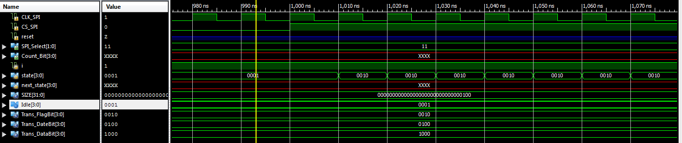
Thank you once again,

I have tried to modified many of thing that you have mentioned but still
don't work.
Is not evaluating even the first state because un the result the CS_SPI
is not working. Even the state and the Count_Bit are not working.

I don't realy know what I am missing.
I will be please to have your help again.
I have attached the description and the result.
1 | `timescale 1ns / 1ps |
2 | ////////////////////////////////////////////////////////////////////////////////// |
3 | // Company: |
4 | // Engineer: |
5 | // |
6 | // Create Date: 17:16:35 12/27/2019 |
7 | // Design Name: |
8 | // Module Name: Projet_Tech_SPI |
9 | // Project Name: |
10 | // Target Devices: |
11 | // Tool versions: |
12 | // Description: |
13 | // |
14 | // Dependencies: |
15 | // |
16 | // Revision: |
17 | // Revision 0.01 - File Created |
18 | // Additional Comments: |
19 | // |
20 | ////////////////////////////////////////////////////////////////////////////////// |
21 | module Projet_Tech_SPI_2( |
22 | CLK_SPI, |
23 | CS_SPI, |
24 | reset, |
25 | Count_Bit, |
26 | SPI_Select |
27 | ); |
28 | |
29 | //------------- Déclaration des entrées ----------------------------- |
30 | input CLK_SPI, CS_SPI, reset; |
31 | //------------- Déclaration des sorties ---------------------------- |
32 | output [1:0] SPI_Select; |
33 | output [3:0] Count_Bit; |
34 | |
35 | //output [1:0] Count_DateBit; |
36 | //output [3:0] Count_DataBit; |
37 | |
38 | //------------- Les ports d'entrées ------------------- |
39 | wire CLK_SPI, CS_SPI, reset; |
40 | //------------- Les ports de sorties ------------------ |
41 | reg [1:0] SPI_Select; |
42 | reg [3:0] Count_Bit; |
43 | reg i=1'b1; |
44 | //reg [1:0] Count_DateBit; |
45 | //reg [3:0] Count_DataBit; |
46 | |
47 | //------------- Les constantes internes --------------------------- |
48 | //assign CS_SPI = i; |
49 | parameter SIZE = 4; |
50 | parameter Idle = 4'b0001, Trans_FlagBit = 4'b0010, Trans_DateBit = 4'b0100, Trans_DataBit = 4'b1000 ; |
51 | |
52 | //-------------Variables internes--------------------------- |
53 | reg [SIZE-1:0] state ;// Seq part of the FSM |
54 | reg [SIZE-1:0] next_state ;// combo part of FSM |
55 | //----------Code startes Here------------------------ |
56 | //assign next_state = fsm_function(state, Idle, Trans_FlagBit, Trans_DateBit, Trans_DataBit); |
57 | |
58 | |
59 | always @(posedge CLK_SPI ) |
60 | begin : MEF_SPI |
61 | |
62 | //state = Idle; |
63 | |
64 | case(state) |
65 | Idle : if(CS_SPI == 1'b0) begin |
66 | state <= Idle; |
67 | SPI_Select <= 2'b11; |
68 | end else if (CS_SPI == 1'b1) begin |
69 | state <= Trans_FlagBit; |
70 | SPI_Select <= 2'b00; |
71 | end |
72 | |
73 | Trans_FlagBit : if(CS_SPI == 1'b1) begin |
74 | SPI_Select <= 2'b00; |
75 | state <= Trans_DateBit; |
76 | //SPI_Select = 2'b00; |
77 | Count_Bit =4'b0010; |
78 | end |
79 | |
80 | Trans_DateBit : if((CS_SPI == 1'b1) && (i!= 1'b0) ) begin |
81 | SPI_Select <= 2'b01; |
82 | Count_Bit <= Count_Bit -1; |
83 | state = Trans_DateBit; |
84 | if(Count_Bit == 4'b0) begin |
85 | i=1'b0; |
86 | end |
87 | |
88 | end else if((CS_SPI == 1'b1) && (i==1'b0) ) begin |
89 | state <= Trans_DataBit; |
90 | Count_Bit <=4'b1011; |
91 | i=1'b1; |
92 | end |
93 | |
94 | Trans_DataBit : if((CS_SPI == 1) && (i != 1'b0)) begin |
95 | SPI_Select <= 2'b01; |
96 | Count_Bit <= Count_Bit -1; |
97 | state <= Trans_DataBit ; |
98 | if(Count_Bit == 4'b0) begin |
99 | i=1'b0; |
100 | end |
101 | end else if((CS_SPI == 1) && (i == 1'b0)) begin |
102 | state <= Trans_FlagBit; |
103 | i=1'b1; |
104 | |
105 | //SPI_Select = 0; |
106 | end |
107 | |
108 | //default : next_state = Idle; |
109 | |
110 | endcase; |
111 | end |
112 | |
113 | endmodule |
You must initialize reg with a valid value. Otherwise its initialized
with X:
https://link.springer.com/chapter/10.1007%2F978-1-4615-1713-9_7
And in your case(state) there is nothing to handle a 4'bXXXX...
Please log in before posting. Registration is free and takes only a minute.
Existing account
Do you have a Google/GoogleMail account? No registration required!
Log in with Google account
Log in with Google account
No account? Register here.