Hi!
I have a problem with IIR filter. On the output I have a input sin
signal but the filter doesn't suppress the signal. It behaviour is that
as rewrite
input signal to output. I think that the problem is in the subtraction
operation or types. Fcut=2MHz. Code below:

library IEEE;
use IEEE.STD_LOGIC_1164.ALL;
use IEEE.STD_LOGIC_unsigned.ALL;
use IEEE.NUMERIC_STD.ALL;

entity dsp is
    Port ( clk : in  STD_LOGIC := '0';
           clk_adc : out  STD_LOGIC := '0';
     clk_dac : out  STD_LOGIC := '0';
           adc_data : in  STD_LOGIC_VECTOR(9 downto 0) := (others =>
'0');
           dac_data : out  STD_LOGIC_VECTOR(9 downto 0) := (others =>
'0')
       );
end dsp;

architecture Behavioral of dsp is


constant coeff_a0: integer := 128; --coefficients
constant coeff_a1: integer := 256;
constant coeff_a2: integer := 128;

constant coeff_b0: integer := -293;
constant coeff_b1: integer := 106;


constant offset: STD_LOGIC_VECTOR(9 downto 0) := "1000000000";

signal adc_buffer: signed(9 downto 0) := (others => '0');
signal dac_buffer: STD_LOGIC_VECTOR(9 downto 0) := (others => '0');

signal mult_a0: signed(19 downto 0):= (others => '0'); --mult registers
signal mult_a1: signed(19 downto 0):= (others => '0');
signal mult_a2: signed(19 downto 0):= (others => '0');


signal mult_b0: signed(19 downto 0):= (others => '0');
signal mult_b1: signed(19 downto 0):= (others => '0');

signal tmult_a0: signed(9 downto 0):= (others => '0'); --truncate
registers
signal tmult_a1: signed(9 downto 0):= (others => '0');
signal tmult_a2: signed(9 downto 0):= (others => '0');


signal tmult_b0: signed(9 downto 0):= (others => '0');
signal tmult_b1: signed(9 downto 0):= (others => '0');

signal add_all: signed(9 downto 0):= (others => '0');

signal pipe_a0: signed(9 downto 0) := (others => '0'); --delay registers
signal pipe_a1: signed(9 downto 0) := (others => '0');
signal pipe_a2: signed(9 downto 0) := (others => '0');


signal pipe_b0: signed(9 downto 0) := (others => '0');
signal pipe_b1: signed(9 downto 0) := (others => '0');


begin

P0: process(clk)
begin

  if falling_edge(clk) then

  adc_buffer <= signed(adc_data); -- adc give data in U2 code

  pipe_a0 <= adc_buffer;
  pipe_a1 <= pipe_a0;
  pipe_a2 <= pipe_a1;

  pipe_b0 <= signed(add_all);
  pipe_b1 <= pipe_b0;

  dac_data <= dac_buffer(9 downto 0); -- write to dac

  end if;

end process;

  mult_a0 <= pipe_a0*to_signed(coeff_a0,10); -- multiplication
  mult_a1 <= pipe_a1*to_signed(coeff_a1,10);
  mult_a2 <= pipe_a2*to_signed(coeff_a2,10);

  mult_b0 <= pipe_b0*to_signed(coeff_b0,10);
  mult_b1 <= pipe_b1*to_signed(coeff_b1,10);

  tmult_a0 <= mult_a0(19 downto 10); -- truncate to 10 bits
  tmult_a1 <= mult_a1(19 downto 10);
  tmult_a2 <= mult_a2(19 downto 10);

  tmult_b0 <= mult_b0(19 downto 10);
  tmult_b1 <= mult_b1(19 downto 10);

  --sum (add and substract)
  add_all <= tmult_a0 + tmult_a1 + tmult_a2 - tmult_b0 - tmult_b1;


  dac_buffer <= STD_LOGIC_VECTOR(add_all) + offset; -- to offset binary
convertion

  clk_adc <= clk;
  clk_dac <= clk;


end Behavioral;
Chris C. wrote:
> if falling_edge(clk) then
THIS IS NONSENSE. THERE IS NO FALLING CLOCK SENSITIVE FF IN AN FPGA.

> clk_adc <= clk;
> clk_dac <= clk;

THIS IS BAD! CLOCKS CANNOT BE ROUTET OUT.

also TRUNCATION IS TO EARLY.
Chris C. wrote:
> use IEEE.STD_LOGIC_unsigned.ALL;
> use IEEE.NUMERIC_STD.ALL;
Use the first one or use the second one. But never ever use both of them
together.
Best is to use the numeric_std and its conversions and casts.
See how simple that is:
http://www.lothar-miller.de/s9y/categories/16-Numeric_Std
Try Google translator, it's German...
Attached files:
-

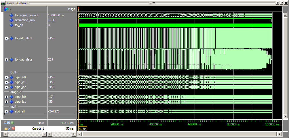
iir_simulation.png
11 KB

Beside all the other mentioned problems:
What is your main clock frequency?

I've added a testbench to the see the filter effect.
For me it looks like your cutoff frequency is to high.

Duke
My clock frequency -> 100MHz

In code below coefficient are for 4MHz cut-off frequency but I dont know
if they are correct. In new code is is easy to change coefficients.
I need coefficients only to test my filter. I would be gratefull if
somebody generate coefficient (10 bit) to low-pass with cut-off beetwenn
1-10MHz.
I dont know what to do with overflow bits. If I have 23-bit ad_all
signal the output amplitude is 4 times lower than when I have 19-bit
ad_all signal.
It probably means that the overflow bits doesn't occur. In my opinion
the sum of 5 signed 19-bit signals should be stored in 23-bit signal.
Secondly is that if I operate on signed values I should be carefull with
math operations signs (+/-). If I add negative values as a constant
signed, in operation of sum of the signals I must use only "+" sign.
I ignored all overflow bits.
It is possible that I have only wrong coefficient. On hardware filter
works but not correct.

My new, some improved code:

library IEEE;
use IEEE.STD_LOGIC_1164.ALL;
use IEEE.NUMERIC_STD.ALL;

entity dsp is
    Port ( clk : in  STD_LOGIC := '0';
     clk_adc : out  STD_LOGIC := '0';
     clk_dac : out  STD_LOGIC := '0';
           adc_data : in  STD_LOGIC_VECTOR(9 downto 0) := (others =>
'0');
           dac_data : out  STD_LOGIC_VECTOR(9 downto 0) := (others =>
'0')
       );
end dsp;

architecture Behavioral of dsp is

constant coeff_a0: integer := 133; --coefficients
constant coeff_a1: integer := 262;
constant coeff_a2: integer := 133;

constant coeff_b0: integer := -164;
constant coeff_b1: integer := 70;

constant offset: signed(9 downto 0) :=  "0111111111"; -- +511 in U2

signal adc_buffer: signed(9 downto 0) := (others => '0');
signal dac_buffer: signed(9 downto 0) := (others => '0');

signal mult_a0: signed(19 downto 0):= (others => '0'); --mult registers
signal mult_a1: signed(19 downto 0):= (others => '0');
signal mult_a2: signed(19 downto 0):= (others => '0');


signal mult_b0: signed(19 downto 0):= (others => '0');
signal mult_b1: signed(19 downto 0):= (others => '0');

signal add_all: signed(19 downto 0):= (others => '0');

signal pipe_a0: signed(9 downto 0) := (others => '0'); --delay registers
signal pipe_a1: signed(9 downto 0) := (others => '0');
signal pipe_a2: signed(9 downto 0) := (others => '0');


signal pipe_b0: signed(9 downto 0) := (others => '0');
signal pipe_b1: signed(9 downto 0) := (others => '0');

begin

P0: process(clk)
begin

  if falling_edge(clk) then

  adc_buffer <= signed(adc_data); -- adc give data in U2 code

  pipe_a0 <= adc_buffer;
  pipe_a1 <= pipe_a0;
  pipe_a2 <= pipe_a1;

  pipe_b0 <= add_all(19 downto 10); --truncated sum
  pipe_b1 <= pipe_b0;

  dac_data <= STD_LOGIC_VECTOR(dac_buffer(9 downto 0)); -- write to dac
(ignore MSB - offset bin conversion)


  mult_a0 <= pipe_a0*to_signed(coeff_a0,10);  -- signed * signed return
20 bit signed
  mult_a1 <= pipe_a1*to_signed(coeff_a1,10);
  mult_a2 <= pipe_a2*to_signed(coeff_a2,10);

  mult_b0 <= pipe_b0*to_signed(coeff_b0,10);
  mult_b1 <= pipe_b1*to_signed(coeff_b1,10);

  --sum of signed results
  add_all <= mult_a0 + mult_a1 + mult_a2 + mult_b0 + mult_b1; --signed +
signed + ...

  dac_buffer <= add_all(19 downto 10) + offset; -- to offset binary
convertion (add 511) signed + signed
    end if;

end process;                               -- dac buffer is 11 bit long

  clk_adc <= clk;
  clk_dac <= clk;


end Behavioral;
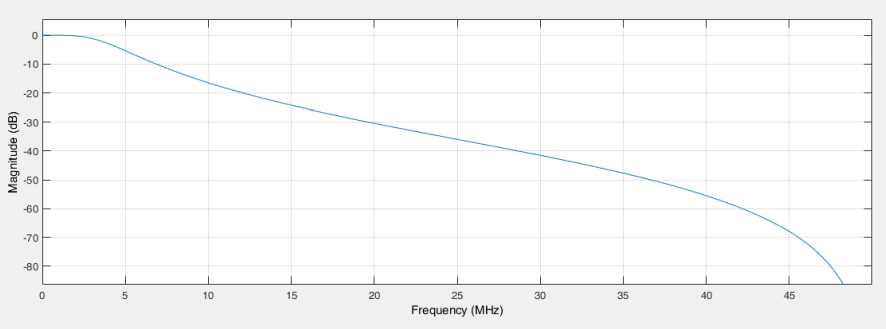
Chris C. wrote:
> In code below coefficient are for 4MHz cut-off frequency but I dont know
> if they are correct.

Did you have a matlab? There is a toolbox available for calculating
filter coeffiecients in fixed data formats. Also do this toolbox a
stability analyis of your IIR filter.

Best Regards,
Attached files:
-

iir_wrong_code.png
14 KB -

iir_matlab_magnitude.png
24 KB -

iir_expected_results.png
14 KB -

iir_expected_with_gain_correction.png
14 KB

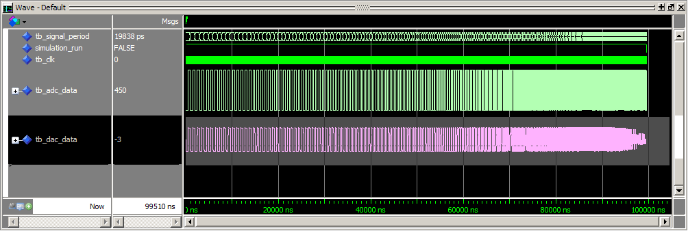
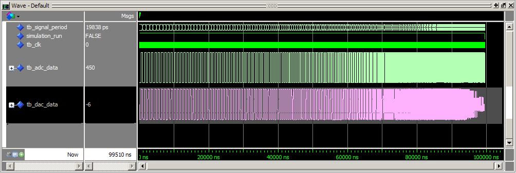
Chris C. wrote:
> It is possible that I have only wrong coefficient. On hardware filter
> works but not correct.
Your coefficents are correct but your code doesn't work.

If I use your coefficients with the implementation biquad, form 1 as
described on this website [1], I got the expected results.

Can you describe graphically the structure of your IIR filter?

Duke

[1] http://www.iowahills.com/4IIRFilterPage.html
Attached files:
-

iir_simulation_work.png
27 KB
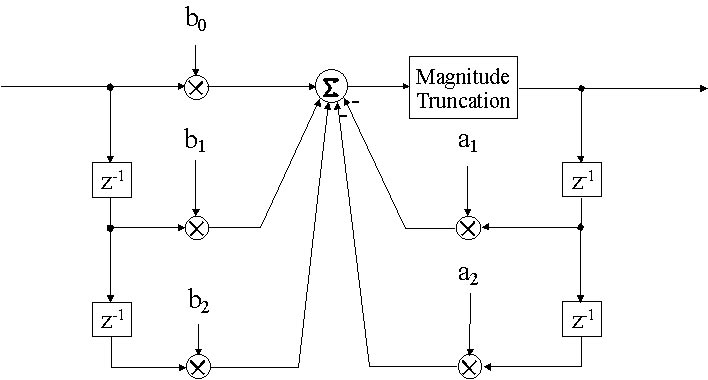
The names in code doesn't match with the schematic, but anyway:

1.  move the multiplications out of your register stage (if *_edge ...
end if)
2.  mind the polarity signs on the big 'adder'
3.  don't move the adder out of the register stage

Another hint (again): Use falling_edge only if you have a good reason.

Duke
Duke Scarring wrote:
> 1.  move the multiplications out of your register stage (if *_edge ...
> end if)
> 2.  .... the big 'adder'

This will led to a lot of logic levels in this case
- 4 adders
- plus 1 multiplier

I would expect timing problems with the code posted by Chris.

Generally it is difficult to run an IIR-Filter with sampling frequency =
clock frequency. Since the feed back loop has only one clock budget but
you need at least two operations, add and multiply. Within a second
order stage (as shown in the iir.jpg picture) there has to be performed
three sequential operations, 2 additions and 1 multiplication. Either
you get many logic levels (in terms of DSP blocks) or to many pipeline
stages.

What is the reason for your IIR-Filter?

Tom
Tom,
I make this filter as a project on high school.
It is very possible that you're right. I spend many hours with trying to
resolve problem with this filter. I obtain results which magnitude
characteristic was above 10dB upper than expected which I compue in FDA
Tool in MATLAB. Interestng is that I implemented FIR filter with the
same way and it works very good. I saw the VHDL code where IIR filter
was divided to machine state (as you described the number of operations
in one clock cycle). Maybe it is a solution of my problem but I need
100MSPS. I think that the problem is in the second part of my filter, it
works but 10dB above.
Please log in before posting. Registration is free and takes only a minute.
Existing account
Do you have a Google/GoogleMail account? No registration required!
Log in with Google account
Log in with Google account
No account? Register here.