I am using a SPARTAN 3E and have used the DCM core to generate a 50 Mhz
to 25 Mhz clock to drive the VGA PORT.
The reset logic I'm using is shown here.
DigitalClockManager instance_name (
.CLKIN_IN(CLK_50MHZ),
.RST_IN(rst_in),
.CLKFX_OUT(clk), //25 Mhz
.CLKIN_IBUFG_OUT(CLKIN_IBUFG_OUT),
.CLK0_OUT(),
.LOCKED_OUT(LOCKED),
.STATUS_OUT(STATUS)
);
BUFG buffer (.I(CLKIN_IBUFG_OUT), .O(CLKIN));
reg LOCKED_R;
reg [3 : 0] SR;
always @ (posedge CLKIN)
begin
if(RESET)
begin
SR [3 : 0] <= 4'b111;
LOCKED_R <=0;
end
else
begin
LOCKED_R <= LOCKED;
if(LOCKED < LOCKED_R | STATUS [1] )// H to L LOCKED | CLKIN UNSTABLE
SR <= {1'b1 , SR[3 : 1]};
else
SR <= {1'b0 , SR[3 : 1]};
end
end
assign rst_in = ( (SR[2] | SR[1] | SR[0]) || RESET);
Now, I am not sure about how to implement reset for all the other
registers in the design, since they are driven by the DCM clock output.
If the RESET signal pulse lasts for a period shorter than what it takes
to assert the locked signal, (which probably will be the case because of
the OR gate at the rst_in), the registers will never be reset.
always @ (posedge clk)
begin
if (LOCKED && !STATUS[1])
begin
//GOOD TO GO
end
else
begin
//RESET
end
end
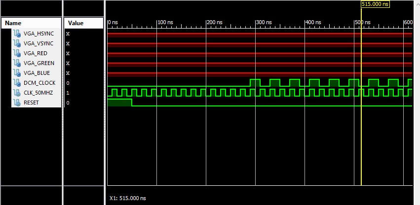
Does the always @ (posedge clk) trigger even when (LOCKED && !STATUS[1])
isn't high? If so, why does the simulation show everything inactive
until the locked bit doesn't go high?
BOTTOM LINE : How can I ensure that the else block triggers?
Is the DCM RESET LOGIC I'm using right?
Attached files:
-

questiondcmpic.jpg
84 KB
Here you can find some real signals from Spartan 3E DCM output:
Beitrag "Re: Spartan 6, dem DCM-Ausgang auf die Finger geschaut"

Sometimes the simulation models are limited.


Ahmed A. wrote:
> Now, I am not sure about how to implement reset for all the other
> registers in the design, since they are driven by the DCM clock output.
For important (and only for that) registers I use a synchronized reset
signal, which is deactivated a couple of clocks later.

Here you can find an example:
Beitrag "Re: Dual Clock FIFO, wie Reset richtig verbinden? VHDL, Atrix7, Vivado"

Duke
Thank you for the input!

From the images/real signals, It seems  that even tough locked goes high
, the clock output isn't valid. I am also monitoring the STATUS[1] bit
in my code, which looks at whether or not CLKIN is stable. This, from
what I could gather, is what the data sheet recommends. So, will
monitoring both these bits essentially prevent tat "false
triggering"/triggering when clock isn't valid and locked is high?

Secondly, I don't understand what you mean by a sync reset for important
registers.I don't know how to implement a completely sync reset for any
dcm clocked registers.


I am thinking of using shift registers wit async resets (@ posedge
locked) and then implementing resets via shifting them and bitwise OR.

Kindly elaborate on how you would implement a sync reset wit DCM clock.

I can't understand the language (GERMAN and VHDL)!


Thank you!
Please log in before posting. Registration is free and takes only a minute.
Existing account
Do you have a Google/GoogleMail account? No registration required!
Log in with Google account
Log in with Google account
No account? Register here.