Guest
#4629757
Hello everybody,

once again I need your help.

I want to built an analog signal to TTL circuit. I already got good
answers to the components in a previsous thread
(https://embdev.net/topic/398991#new).

Now I am struggling with the next step, which is to integrate the LM311P
into my circuit. I am not sure how to wire it properly to get the signal
I want.

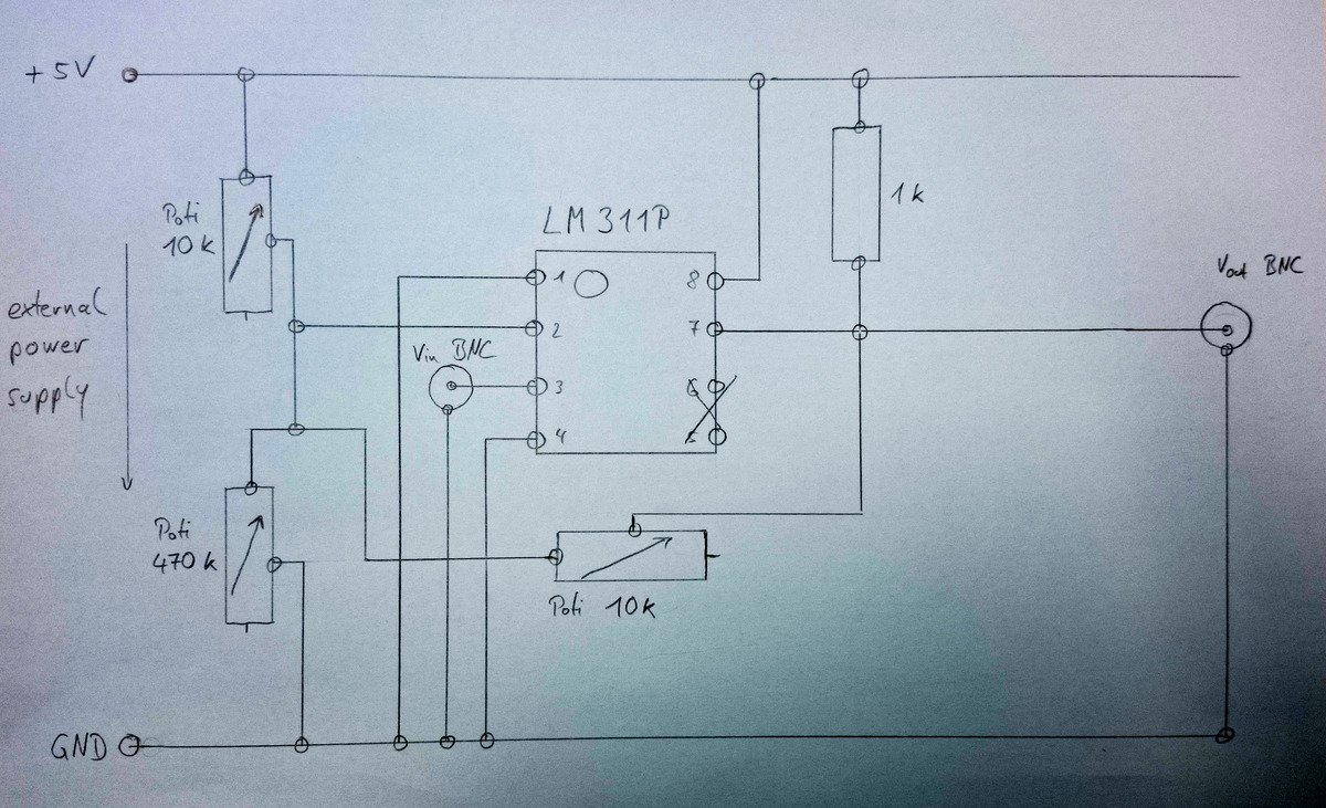
Attached you find a drawing of how I would built it, based on my poor
knowledge about that topic so far.

So basically I have a V_in signal from a BNC (Voltage levels e.g.
between 2.3 and 2.7 Volts) and I want to have a 0->5 Volts TTL signal at
V_out to a BNC.
I would use a external power supply to get the required 5V for the Vcc+.
Also my potentiometers (Poti) are used to adjust my Voltage devisions
within the circuit to adjust the switching voltage and the hysteresis.

The biggest uncertainty is the 1k resistor between the 5 Volts from the
power supply and the V_out. As far as my understanding of the working
principle of the LM311P is right, it switches at V_out (#7) between GND
(direkt link to #1) or it blocks the link to #1 and so there are the 5
Volts at V_out. So the 1k resistor in this case just limits the current.

Am I right with this?
How can I improve the circuit diagram?

If something is unclear, please feel free to ask!
Thank you very much in advance!

Regards,
Valentin
Attached files:
-
 circuit_plan.jpg
(230 KB)
circuit_plan.jpg
(230 KB)