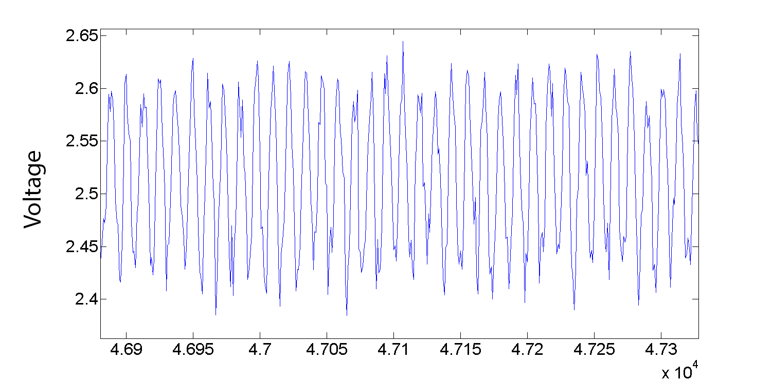
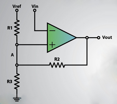
Dear community,

I am usually more an aerodynamic expert than an electronic guy and that
is why I need your help.

I have a fluidic oscillator working at frequencies around 5kHz and I
want to do optical measurements. Since the laser and camera system is
not able to work at such high frequencies I need to do phase locked
measurements. Therefore it is important to more or less hit the same
phase angle of the oscillation with each measurement shot.

I do have an "online" voltage signal from hot wire measurements. To
generate a 0->5Volt TTL trigger signal I need a circuit arrangement with
a deterministic and short time delay.

The goal is to start with the phase locked measurements at one point of
the oscillation (defined phase angle equal to 0°) and later on add
defined time delays to achieve phase angles of 30°, 60° and so on. Where
exactly I start is not important.

A snapshot of the voltage signal I have at 5kHz is attached. Also there
is a curcit suggestion I thought about.

I also would like to have a hysteresis to have a stable circuit against
noice and signal flucutations, therefore it is based on the Schmitt
trigger principle.

If I choose for the given circuit Vref = 5V, Vin as my voltage signal
and the resistors to R1 = 5kΩ, R = 5.1kΩ and R3 = 200kΩ I should get
Vin_switch1 = 2,49V and Vin_switch2 = 2,56V.

The Vout as a result should switch between 0 and 5V.

My first question is, am I correct with this circuit and my
calculations?
Second, if I am right is it better to choose smaller resitors or higher
resistors (since it it only a matter of their relations) to achieve
minimal delay times due to the circuit.
Third, is there any other/easier/smarter way to get my "online" TTL
signal?

I hope I explained everything in an understandable way. If not please
feel free to ask!

Thousand thanks in advance!
Valentin
Attached files:
-

voltage_signal.jpg
410 KB -

circuit.jpg
60 KB
valentin88 wrote:
> R1 = 5kΩ, R = 5.1kΩ and R3 = 200kΩ
> My first question is, am I correct with this circuit and my calculations?
You must swap R2 and R3 values...
And I would make R1 and R3 = 4k7 and a trimmer resistor of 500 R between
them:
1 | +5V o |
2 | | |
3 | - |
4 | | | |
5 | | | R1 |
6 | | | 4k7 |
7 | - |
8 | | |
9 | - | |
10 | | | | |
11 | | |<-----------o--- |
12 | | | Radj |
13 | - 500R |
14 | | |
15 | - |
16 | | | |
17 | | | R3 |
18 | | | 4k7 |
19 | - |
20 | | |
21 | --- |
> to achieve minimal delay times due to the circuit.
You must select a comparator. Those are able to get out of output
saturation much faster than "usual" OP amps.
Thank you very much for your fast reply!

The trimmer resistor is a brilliant idea so I can adjust the hysteresis!
Also 4.7kΩ is more "centered" around my medium voltage value!

After thinking a while I found my mistake. Switched R2 and R3 for the
Vin_switch2 calculations ...

What do you mean with "select a comparator"? I thought I use 3 resistors
and one comperator for this circuit?

Thanks!
Valentin
valentin88 wrote:
> one comperator

Yes, one is enough.

In principle one could build any op-amp based function with any op-amp.
But for your application, that is, to compare signal levels, and change
output polarity at defined levels, and all of that with relatively high
speed, at relatively high repetition rate (frequency), you´d need a
dedicated, fast type of op-amp.

So Lothar didn´t mean that you would have to select one comparator out
of a couple of comparators on your circuit board - he only wanted you to
choose (or simply "use") the right type of operational amplifier: A
comparator, cause this type is dedicated for things like that.

Maybe you knew that before - but maybe not.
It helped me a lot! Like I said, this is all new for me and even though
I try to get all this I am not too sure about the components.

So ... What I am planning to get for the circuit is:

a single comperator: I thought about the LM311
two potentiometers: linear, 10k (so I can choose 4.7k and can also
adjust the middle voltage in case that I need to adjust them)
one potentiometer: linear, 500k (for the hysteresis)

Some wires, two BNC plugs (both the signal in & out goes with a BNC
connection), soldering iron (to get everything together) and a 5V power
supply to get the circuit running.

Is the LM311 suitable for the circuit?
You think this will work out with those components?
Is it better to have two fixed resistors instead of using potentiometers
for all of it or does it only matter in therms of the component prices?

Thanks!
Valentin
Please log in before posting. Registration is free and takes only a minute.
Existing account
Do you have a Google/GoogleMail account? No registration required!
Log in with Google account
Log in with Google account
No account? Register here.