Hi all! I wrote the polyphase filter decimator on VHDL, decimation
factor M=6.
The testbench showed decimation, but data in out bus is not correct. Can
someone look in my code and get advice to me how i can fix it?
Dmtry Karlin wrote:
> but data in out bus is not correct.
What is not correct with it? What do you expect and what do you get?


> advice to me
Use indentation to get a readable code! When each line starts at the
very beginning of the line no one can see any structure.

This snippet of code here:
1 | begin
|
2 | pipeline2: process(c) |
3 | begin
|
4 | if ( rising_edge(c) ) then |
5 | for i in 0 to 4 loop |
6 | case i is |
7 | when 0 => |
8 | m10 <= signed(x10)*signed(h10); |
9 | when 1 => |
10 | m11 <= signed(m10) + signed(x11)*signed(h11); |
11 | when 2 => |
12 | m12 <= signed(m11) + signed(x12)*signed(h12); |
13 | when 3 => |
14 | m13 <= signed(m12) + signed(x13)*signed(h13); |
15 | when 4 => |
16 | m14 <= signed(m13) + signed(x14)*signed(h14); |
17 | dout_reg1 <= m14; |
18 | when others => null; |
19 | end case; |
20 | end loop; |
21 | end if; |
22 | end process pipeline3; |
... can be replaced without any change in functionality(!!!) with this
here:
1 | begin
|
2 | pipeline2: process(c) |
3 | begin
|
4 | if ( rising_edge(c) ) then |
5 | m10 <= signed(x10)*signed(h10); |
6 | m11 <= signed(m10) + signed(x11)*signed(h11); |
7 | m12 <= signed(m11) + signed(x12)*signed(h12); |
8 | m13 <= signed(m12) + signed(x13)*signed(h13); |
9 | m14 <= signed(m13) + signed(x14)*signed(h14); |
10 | dout_reg1 <= m14; |
11 | end if; |
12 | end process pipeline3; |
And without this obfuscation you see the problem clearly: it is a bug
due to the behaviour of signals in processes.

1. A signal KEEPS its start value throughout the whole process!
2. At the process END it gets the last assigned value as its NEW value.

So here I could write this process without ANY change in behaviour(!!)
like that:
1 | begin
|
2 | pipeline2: process(c) |
3 | begin
|
4 | if ( rising_edge(c) ) then |
5 | m13 <= signed(m12) + signed(x13)*signed(h13); |
6 | dout_reg1 <= m14; |
7 | m14 <= signed(m13) + signed(x14)*signed(h14); |
8 | m12 <= signed(m11) + signed(x12)*signed(h12); |
9 | m10 <= signed(x10)*signed(h10); |
10 | m11 <= signed(m10) + signed(x11)*signed(h11); |
11 | end if; |
12 | end process pipeline3; |
Think about it...
Hi Lothar! Thank you for your answer. I'm sorry, but i have an new
question.
(I started to learn FPGA and VHDL only 1 month ago and have no
expirience in this place ).

I don't understand this your words: "1. A signal KEEPS its start value
throughout the whole process!
2. At the process END it gets the last assigned value as its NEW value."

Why? The input samples are multiplied on coefficients and summed. How
they doesn't change the values the whole process?
Dmtry Karlin wrote:
> Why?
To keep things short: thats the way signals behave in VHDL. And if you
are a little bit mor experienced you will see: thats really good!

> How they doesn't change the values the whole process?
A signals value only changes at the end of a process (or at a
wait-statement).

> The input samples are multiplied on coefficients and summed.
If you want to change the value "immediately" you must use variables.

But you must always be aware: you don't program anything with VHDL!
You describe hardware (as VHDL is a Hardware Description Language)!
And to describe something you must have a clear picture of that. You
cannot describe how it is at the north pole if you have never seen it or
at least a photo of it...
What can you say about this code? Am i going at right way?
1 | pipeline1: process(c) |
2 | variable i1 :integer := 0; |
3 | begin
|
4 | if ( rising_edge(c) ) then |
5 | case i1 is |
6 | when 0 => |
7 | m10 <= signed(x10)*signed(h10); |
8 | when 1 => |
9 | m11 <= signed(m10) + signed(x11)*signed(h11); |
10 | when 2 => |
11 | m12 <= signed(m11) + signed(x12)*signed(h12); |
12 | when 3 => |
13 | m13 <= signed(m12) + signed(x13)*signed(h13); |
14 | when 4 => |
15 | m14 <= signed(m13) + signed(x14)*signed(h14); |
16 | when 5 => |
17 | dout_reg1 <= m14; |
18 | when others => null; |
19 | end case; |
20 | if ( i1 < 6) then |
21 | i1 := i1 + 1; |
22 | else i1 := 0; |
23 | end if; |
24 | end if; |
25 | end process pipeline1; |
Dmtry Karlin wrote:
> What can you say about this code?
This will work.
> Am i going at right way?
That far: yes. But keep in mind, that now the calculation eats up 6
clock cycles.

But the name is wrong: you don't have a pipeline! When you put 1 barrel
into a pipeline 1 barrel comes out at the very same time on the other
end. Of course it is not the same barrel, this will show up at the
output several barrels later...

So pipeline means in computer technology: with each clock goes 1 item in
and 1 item out. The depth of the pipeline says how much items are inside
the pipeline. That's called Latency.

Your design is easy pipeable: just kick off that case-thing and the
counter. Done.
Lothar Miller wrote:
> Your design is easy pipeable: just kick off that case-thing and the
> counter. Done.

But i must to get out-samples after 6 clock cycles.
Algorithm : in-data comes through the subfilter for 6 clock cycles, and
only after this 6 cycles we can to get data on out bus.

How i can do it without case and counter?

I have found a few problems in my code.

1) I use in subfilters the same clock signal that i change value of
coommutator. If i call clock of commutator as c and call clock of
subfilters as c', the relation between c and c' is c = 6*c' ( i mean
frequencies , of course ).

2) A coefficients for polyphase filter are took from a filter-prototype.
Let a filter-prototype has N coefficients and decimation factor is M .
Then each subfilter has N/M number of coefficients.

Is it all true?
Dmtry Karlin wrote:
> How i can do it without case and counter?
This is a real pielined design:
1 | begin
|
2 | pipeline2: process(c) |
3 | begin
|
4 | if ( rising_edge(c) ) then |
5 | m10 <= signed(x10)*signed(h10); |
6 | m11 <= signed(m10) + signed(x11)*signed(h11); |
7 | m12 <= signed(m11) + signed(x12)*signed(h12); |
8 | m13 <= signed(m12) + signed(x13)*signed(h13); |
9 | m14 <= signed(m13) + signed(x14)*signed(h14); |
10 | dout_reg1 <= m14; |
11 | end if; |
12 | end process pipeline2; |
With every clock new input goes in, every intermediate value is
calculated and one output goes out with 6 clocks latency.

If you want to do it in 1 clock cycle you must write it with variables:
1 | begin
|
2 | pipeline2: process(c) |
3 | variable m10, m11, m12... : signed(...); |
4 | begin
|
5 | if ( rising_edge(c) ) then |
6 | m10 := signed(x10)*signed(h10); |
7 | m11 := signed(m10) + signed(x11)*signed(h11); |
8 | m12 := signed(m11) + signed(x12)*signed(h12); |
9 | m13 := signed(m12) + signed(x13)*signed(h13); |
10 | m14 := signed(m13) + signed(x14)*signed(h14); |
11 | dout_reg1 <= m14; |
12 | end if; |
13 | end process pipeline2; |
The only remaining question is: how fast can the clock be at maximum? It
will be fairly slow, because there are 5 multipliers and 4 addders one
behind each other to be done in one clock cycle. Thats fairly lots of
stuff...
Lothar Miller wrote:
> With every clock new input goes in, every intermediate value is
> calculated and one output goes out with 6 clocks latency.

But how i have found a few hours ago, i need 10 coefficients on 1
subfilter.
Look: the filter-protoype has 60 coefficients, decimation ratio is 6,
60/6=10.

Therefore, now my code has next form, i think:
1 | pipeline1: process(c) |
2 | begin
|
3 | if ( rising_edge(c) ) then |
4 | m10 <= signed(x10)*signed(h10); |
5 | m11 <= signed(m10) + signed(x11)*signed(h11); |
6 | m12 <= signed(m11) + signed(x12)*signed(h12); |
7 | m13 <= signed(m12) + signed(x13)*signed(h13); |
8 | m14 <= signed(m13) + signed(x14)*signed(h14); |
9 | m15 <= signed(m14) + signed(x15)*signed(h15); |
10 | m16 <= signed(m15) + signed(x16)*signed(h16); |
11 | m17 <= signed(m16) + signed(x17)*signed(h17); |
12 | m18 <= signed(m17) + signed(x18)*signed(h18); |
13 | m19 <= signed(m18) + signed(x19)*signed(h19); |
14 | dout_reg1 <= m19; |
15 | end if; |
16 | end process pipeline1; |
Now one output goes out with 10 clocks latency. But i need to save 6
clock latency, is not it?
Attached files:
-

layons.jpg
68 KB
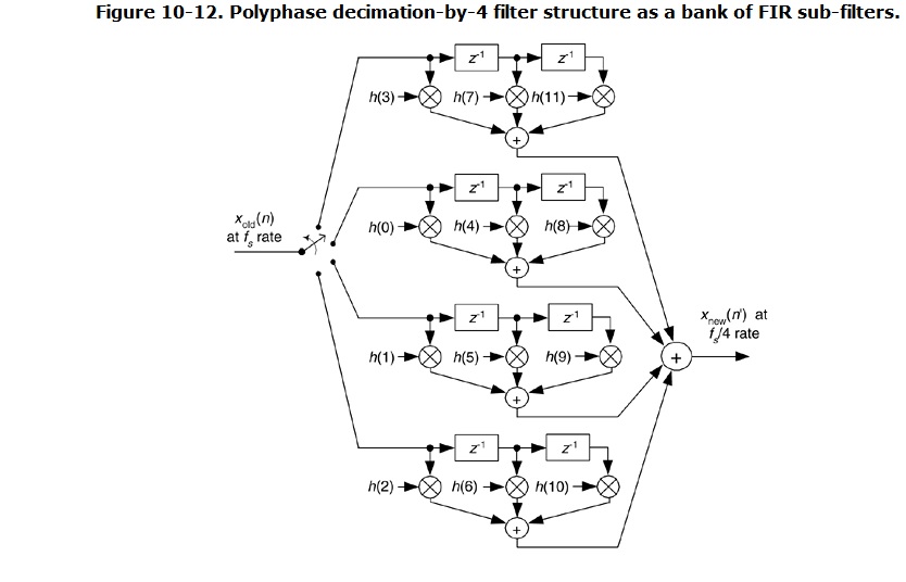
I'm confused.

My filter is polyphase ( multirate ) filter with function of decimation.
The decimation factor is M.
A polyphase filter structure : a input bus,a commutator,a bank of
subfilters,a output bus.
Let call a sampling frequence of data in input bus as Fs.
Let call a decimation factor as M.
Therefore, subfilters are working on a sampling frequence Fs / M.
A subfilter is FIR-filter. Coefficients for subfilter we take from FIR
filter-prototype.
Let call a number of cofficients of prototype as N. Therefore, a number
of cofficients of a subfilter is N / M.
We must take coefficients of prototype with the rule. The rule: if we
watch on impulse response of prototype, we must take coefficients from
left to right. For example, by 1st subfilter: let the leftmost
coefficient from impulse response has a number is zero (0). Therefore,
for our 1st subfilter we must take coefficients with numbers
0,6,12,18,24,30,36,42,48,54. For 2th subfilter:
1,7,13,19,25,31,37,43,49,55, and etc (if i have prototype with 60
coefficients).
Now, let's talk about a bank of subfilters. We have M sudfilters here,
because our decimation factor is M. Data from input bus are entered on
subfilters not at the same time. A function of distributor is performed
commutator. It is hard to describe all in this process ( because my
English is bad ) and i have just illustrated it with picture from R.
Layons's book "Understanding digital processing". I can say only that
our 1st subfilter is last in turn of commutator.
But how much of clocks a signal is processing in each subfilter? I think
it is M clock. One output goes out with M clocks latency,and one clock
is N / M of time, is not it?

And how we summed of signals from output buses of subfilters? Let
commutator is on start position. A signal from input bus come at
subfilter with a number M. After one clock, a signal from input bus come
at subfilter with a number  M-1. But what about output signal from the
subfilter with number M? Does he come at adder or it must wait output
signals from another M-1 subfilters? I don't understand this matter.

P.S. I apologize for my bad English. If you can not understand some of
my expressions, tell me about it, i will try do it better in future.
Thanks for your help.
Ignore a little bit of my rave, I'm just tired.

The last edition of my filter, check it please.
Dmtry Karlin wrote:
> check it please.
You should check it.
If you enceounter any problems with it you can ask. and if its working
you should post an acknowledge here for a neat end of the thread.

BTW: are all the filters the same except for the h values?
If so: why not using only one filter component and passing those
constants via a generic parameter?
You are using the full input clock rate on the subfilters, but for the
polyphase decimator the should be run at the output clock rate, (1/6 in
your case)
Lothar Miller wrote:
> are all the filters the same except for the h values?

Yes.

Lothar Miller wrote:
> why not using only one filter component and passing those
> constants via a generic parameter?

I thought about it. It is hard to me say why, i can say only that i have
reasons why i did it so.

Lattice User wrote:
> You are using the full input clock rate on the subfilters, but for the
> polyphase decimator the should be run at the output clock rate

I understant this thing. Are you mean that i need one more clock signal
in the block of input signals?
Dmtry Karlin wrote:
>> You are using the full input clock rate on the subfilters, but for the
>> polyphase decimator the should be run at the output clock rate
>
> I understant this thing. Are you mean that i need one more clock signal
> in the block of input signals?

Using multiple clocks will only create a chaos.
You should use enable signals for the subfilters. Generate these enables
from your commutator.
1 | if ( rising_edge(c) ) then |
2 | if ( Enable ) |
3 | ....
|
4 | endif; |
5 | end if; |
I have did it from the beginning. I re-wrote my filter with another
structure.
The result of simulation is similar to the truth, but i need to rise up
limit of clock signal. In the time, the limit is 113-114 MGz, but i need
the limit is 120 MGz. Can you tell me about some of methods how i can do
it (only names ) ?
Dmtry Karlin wrote:
> Can you tell me about some of methods how i can do it (only names ) ?
Static Timing Analysis --> Critical Path
http://en.wikipedia.org/wiki/Static_timing_analysis

Your toolchain (Which one for which chip?) will have something to do
that. And when you know the critical path you  will have to examine it a
little bit closer...

BTW: that chapter called "Indentation" you should read once more and in
deep!
I'm sorry, i did some important deals.

My mentor said that i can use CIC + FIR. I wrote it. Is it better?
Please log in before posting. Registration is free and takes only a minute.
Existing account
Do you have a Google/GoogleMail account? No registration required!
Log in with Google account
Log in with Google account
No account? Register here.