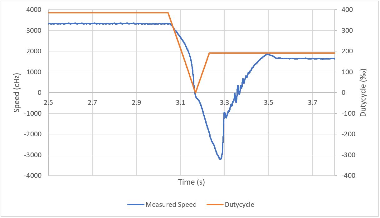
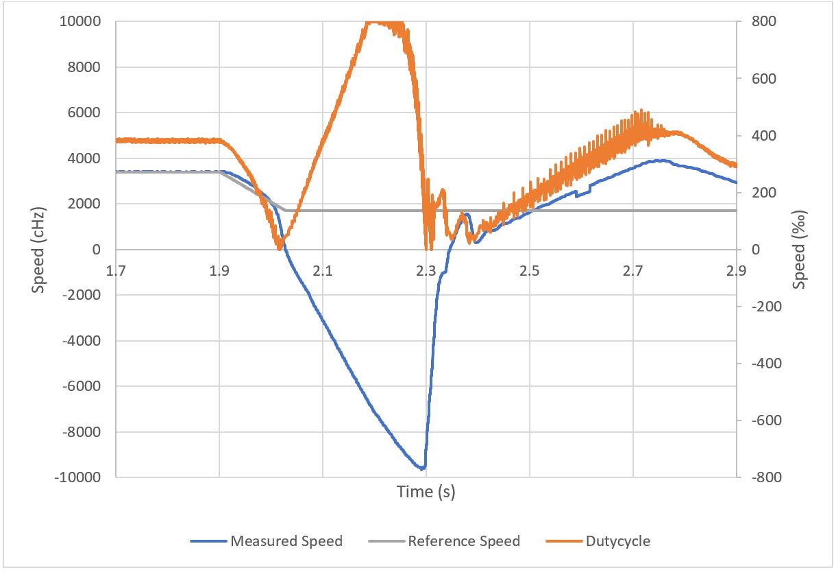
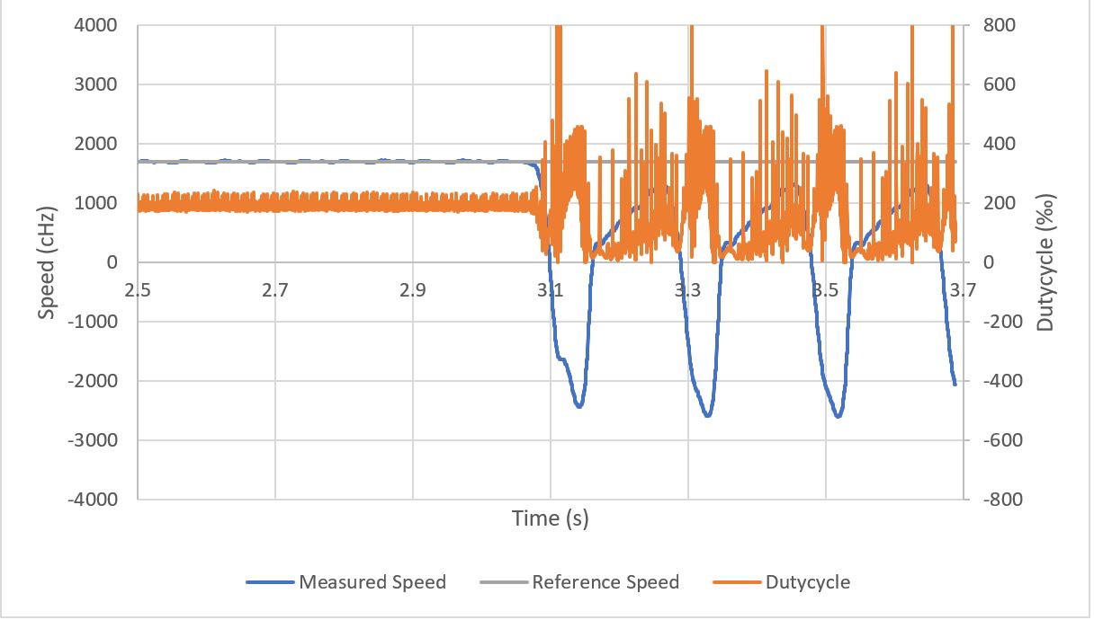
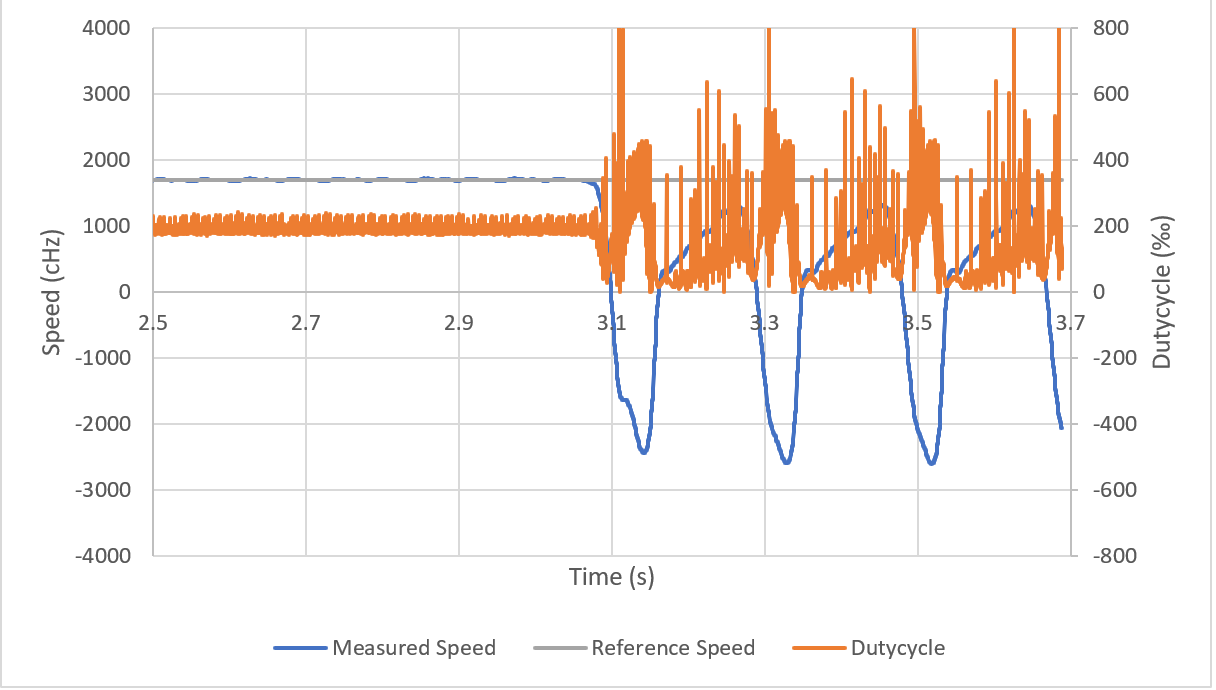
Hello,

I am currently doing a project to develop a controller for a BLDC motor.
The controller is implemented on the microcontroller TMS320F280049 and
as the FET-Driver I use the DRV8323RH (both from Texas Instruments).

So, the motor controller with a 6-step commutation algorithm is
implemented using the Eval-boards from TI which are the LaunchPad
LAUNCHXL-F280049C and the BoosterPack BOOSTXL-DRV8323RH (I attached the
schematic of the BooserPack).
The rotor position of the BLDC-motor is determined via a small magnet
which is mounted on the end of the motor shaft and measured by a
magnetic encoder (MA730).
The controller generally works, except for apparently one abnormal
behavior which can be seen in different operation modes:

1) The Direct-PWM-Mode, in which the user sets the dutycycle of the PWM
manually and the controller just energizes the motor phases according to
the current sector and the 6-step commutation algorithm.
Here, when the dutycycle is given a (more or less) steep ramp downwards
to zero and then immediately (or with a pause of a few milliseconds) a
ramp upwards again the motor suddenly accelerates in backwards direction
before it runs with the speed which matches the given dutycycle. (see
attached Image_1.bmp)


2) Velocity-Mode, with cascaded PI-controllers for current control
(inner loop) and speed control (outer loop).
Here, a similar behavior is observable when the controller wants to
decelerate with a steep ramp from a higher rotation speed to a lower
one. (see attached Image_2.bmp)

3) Again in Velocity-Mode. This time the reference speed is kept
constant. But when the motor is blocked manually it again accelerates
for a moment in the wrong direction. (see attached Image_3.bmp)

It is not a PI-controller issue! All the controller outputs were
monitored and they always demand a movement in positive direction as you
can see on the dutycycle which is the last output of the cascaded
PI-controller system.

It was also confirmed with oscilloscope and a datalogger that the PWM
signals of the microcontroller and the gate voltages of the inverter
stage match and are configured for rotation in positive direction
(depending on the 6-step commutation sector).

By comparing the mentioned 3 cases it seems that the problem occurs when
the dutycycle decreases rather quickly and increases again.

I am out of ideas of what causes this behavior and how to get rid of it.

I would be thankful for any suggestions.
Attached files:
-

Image_1.bmp
3.2 MB -

Image_2.bmp
3.9 MB -

Image_3.bmp
3.2 MB
Please log in before posting. Registration is free and takes only a minute.
Existing account
Do you have a Google/GoogleMail account? No registration required!
Log in with Google account
Log in with Google account
No account? Register here.