Problems to compare impedance AD5933 and Agilent LCR meter E4980A

#7707740
Rate this post
useful
not useful

Hello,

I´m currently working with the impedance converter AD5933. I´m having some problems to compare the data that I get from the AD5933 with a LRC meter. I start my measurement by configurating my frequency start, the increment and number of increments. In my case I´m running frequency sweep with a range from 1kHz to 100kHz.

I started by calculating the gain factor with a know impedance, and then I start my measurement. I get the real and the imaginary data from the register specify at the datasheet, then I calculate the magnitude and the impedance also with the formulas that are in the datasheet.

However when I want to compare the impedance that I get with a LCR meter, the data is different and I don´t really know why. I have done some examples as explained in the datasheet but I don´t know if there is any detail that I´m missing.

To double check my data I also got the resistive and reactive from my impedance convertor and the phase (as specify in the datasheet) but I have not yet have any success.

Have someone had something similar?

Thanks Daphne
#7708035
Rate this post
useful
not useful

However when I want to compare the impedance that I get with a LCR meter, the data is different and I don´t really know why.

Can you show a graph which compares the two impedance curves and phase curves? What device under test do you use?
It could be a could idea to use a well known circuit like a LCR resonance circuit to test the measurement setup and compare it to the reference LCR meter.

#7708205
Rate this post
useful
not useful

so from the datasheet (https://www.analog.com/media/en/technical-documentation/data-sheets/AD5933.pdf) I´m following the "measuring the phase across an impedance" section.

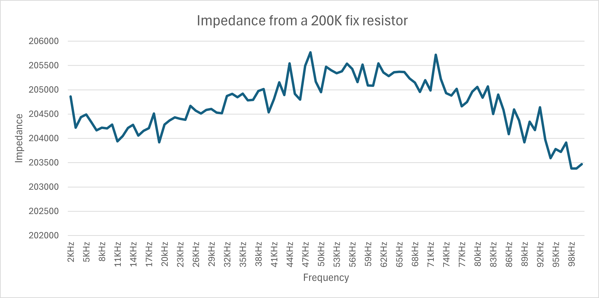
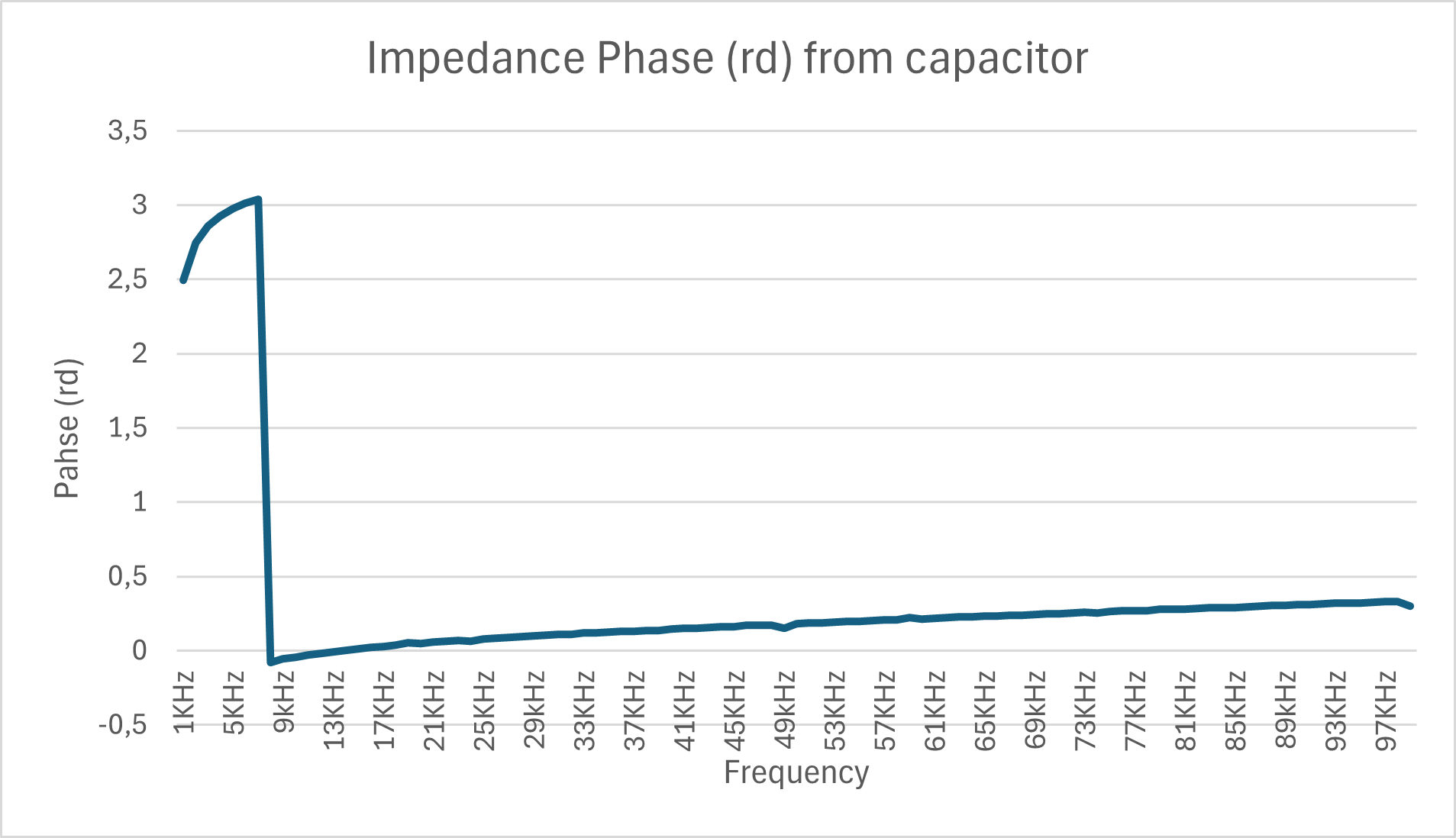
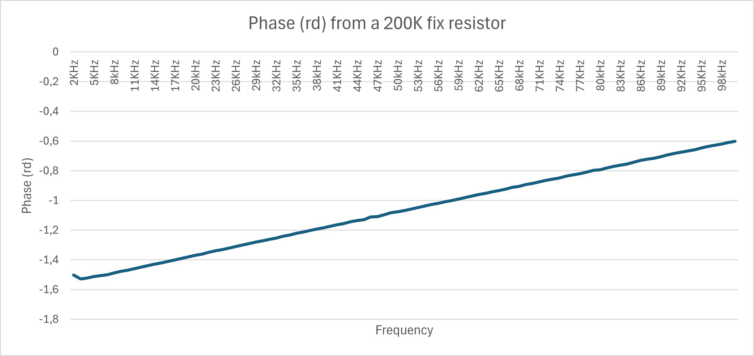
The first step says that I should add a know impedance between the Vin and Vout, in my case I´m using a 200K resistor. From this value I should get the impedance phase of the system, my result is the chart attach. Once this step is done, it says in the datasheet that I should use an unknow impedance and also run a frequency sweep.

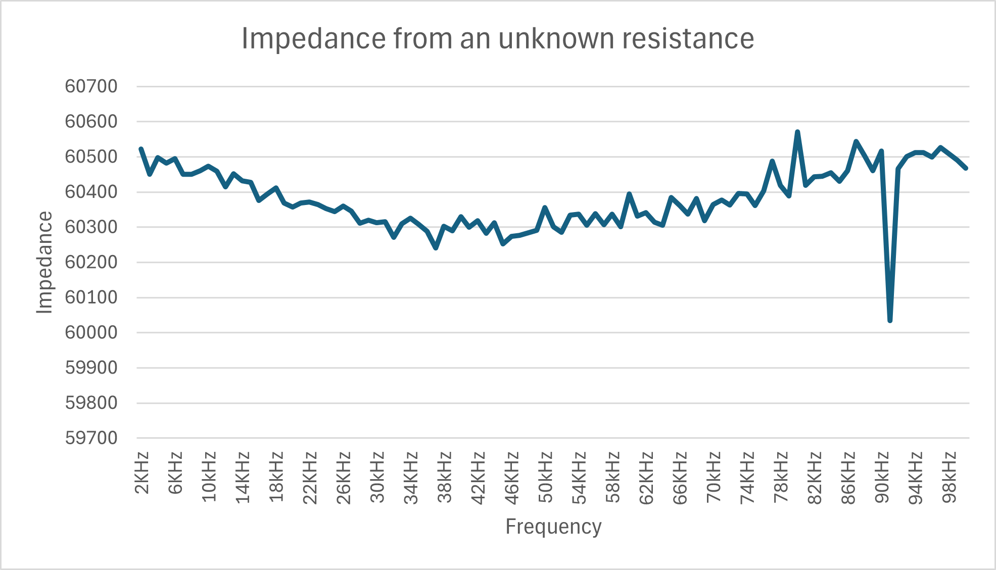
Once I have those values I need to get the Impedance phase from the "unknow impedance", and to do so rest the impedance from the unknow resistance - phase from the system.

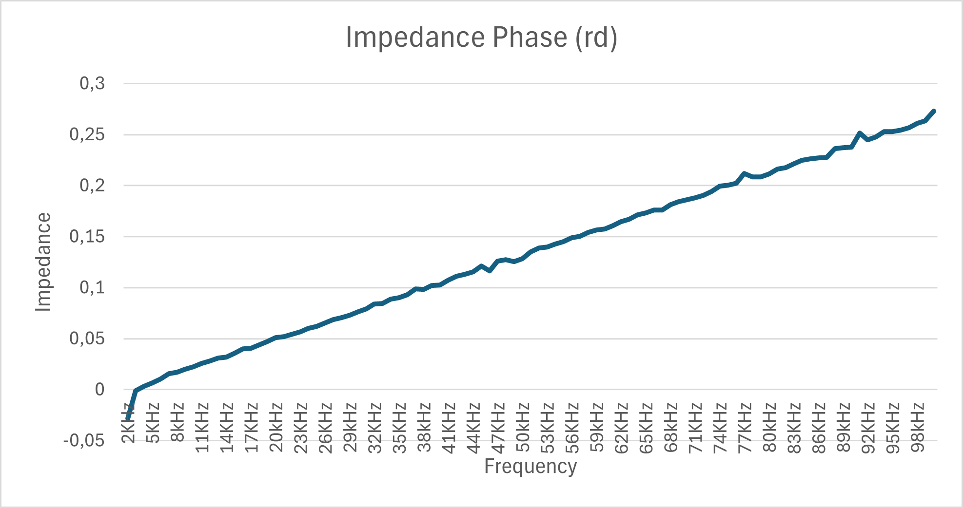
I did this calculation and my results are the charts label "Unknow impedance phase". Once that part was done I compare with my LRC meter and the results were not that far from each other.

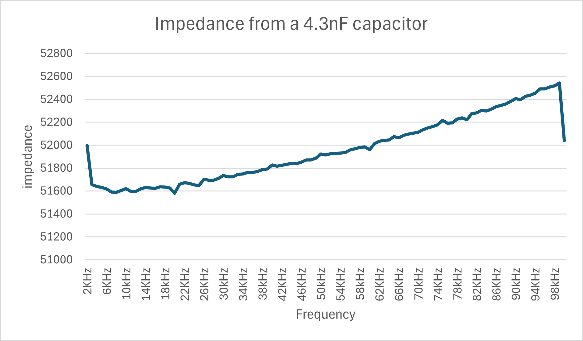
However!! I run the same measurement with a capacitor, in this case a 4.3nF and did the same procedure and in the datasheet it says that the difference between capacitor to resistance should be -90. But I don´t get those results and the data that I obtain from the impedance converter AD5933 is not matching with the data from the LRC meter.

I have check my calculations and the data but I have not been success on finding the error.

Maybe if you see something that I´m not seeing you could please let me know :)

Thanks! Daphne

#7710281
Rate this post
useful
not useful

-90 degrees unit, sorry for not clarify it before.

So, I have been doing some measurements and I realize that the Gain resistor that I apply as my external feedback resistor is having a big impacts in my data and therefore I cannot compare the data.

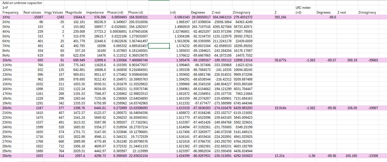
In the annexed picture I have add the data I´m getting from my impedance analyzer, and the calculations that I have with the formulas of the datasheet. I´m using a 1K external resistor and I was measuring a 1nF capacitor. I´m just comparing the points at 10kHz, 20kHz and 30kHz.

So, as I say I think the external resistor has a big incluence in my results, I´m a little out of ideas of what to do or If I´m missing something.

Thanks for the help :) Daphne

#7710732
Rate this post
useful
not useful

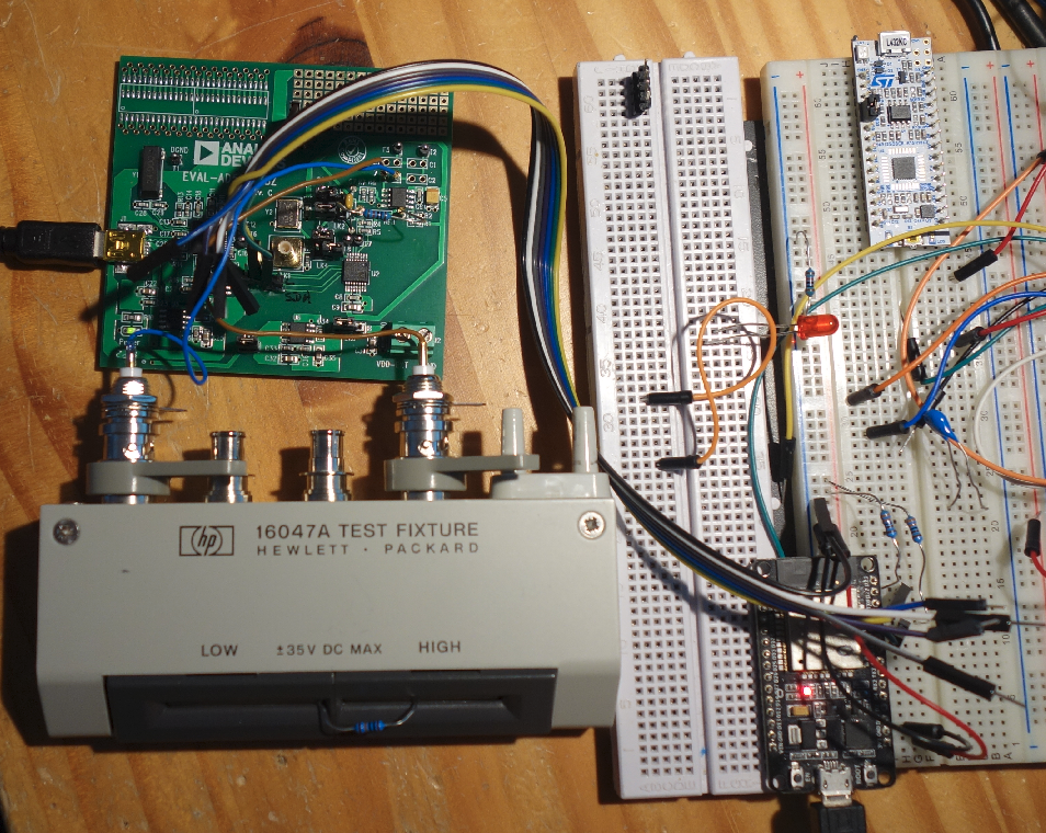
You should specify the test circuit somewhat more precise and what the meaning of the numbers is. A photograph of your setup might help to identify problems regarding the cabling.

I guess that all numbers in your table are wrong. If you have a DUT that contains an 1k resistor, then the real part of the impedance should always be 1000 Ohms! Without any frequency dependency and regardless whether you have the 1nF capacitor in parallel or series connected.

#7712257
Rate this post
useful
not useful

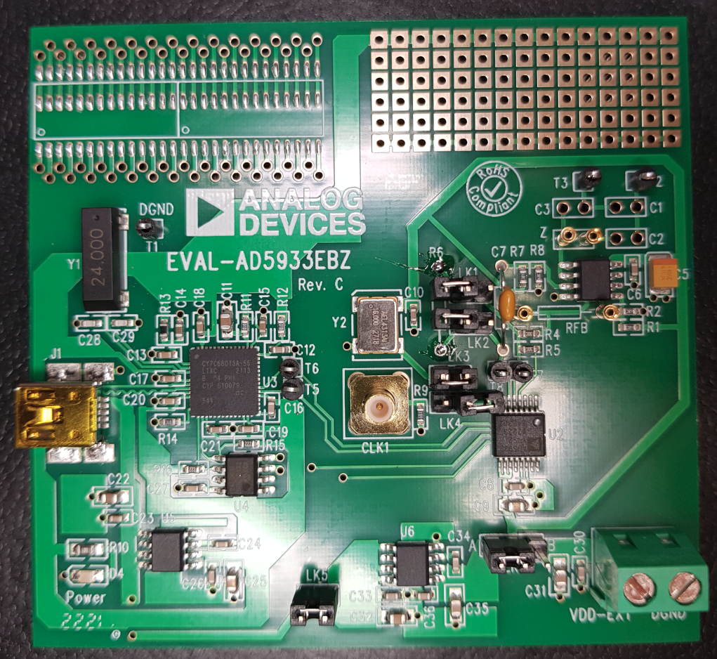
I think the AD5933 is a quite interesting device, so I bought an evaluation board.
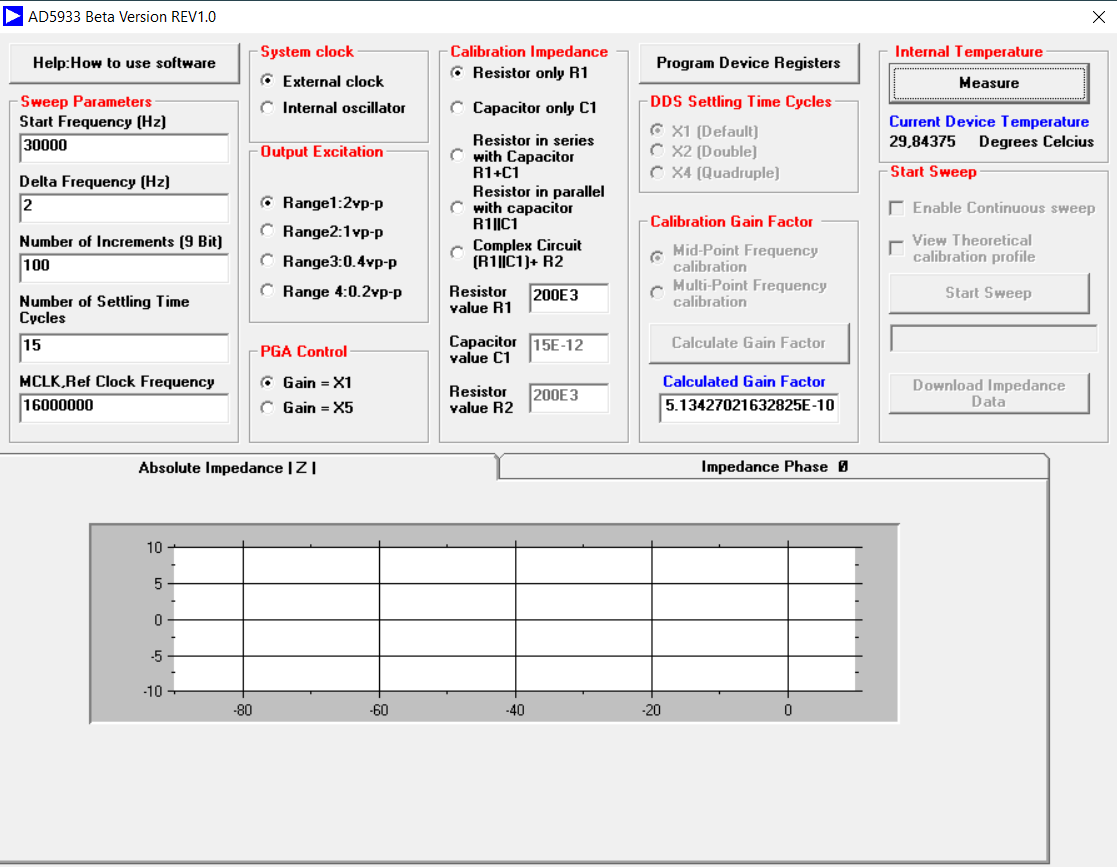
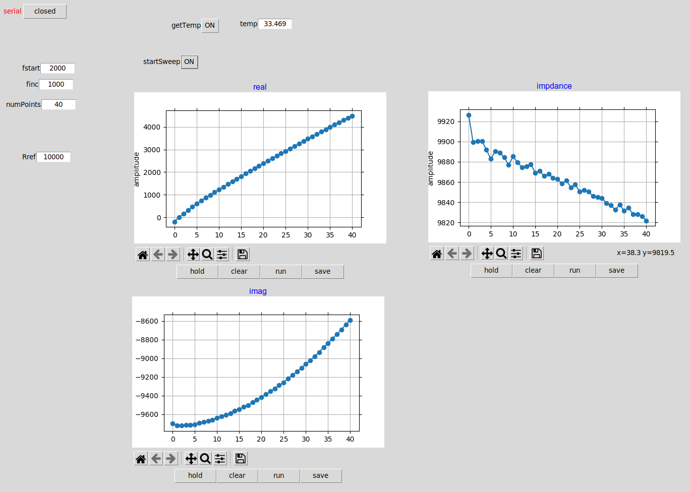
But the start is not so easy as expected, because the LCR-measurement part is greyed out in the GUI. I would expect that the drivers are installed correctly. When I press the button "Internal Temperatur : Measure" the temperature of the chip is diplayed ( When I hold my finger on the chip, the temperature is rising).
Does anybody have an idea what's the problem?

Attached files:
#7712437
Rate this post
useful
not useful

Christoph M. wrote:

Do you have the eval board yourself or some experience with this chip?

I dont have the eval board but an early sample of the AD5933 since 2005. At that time I studied the datasheet but when the NanoVNA came along I stopped that project.

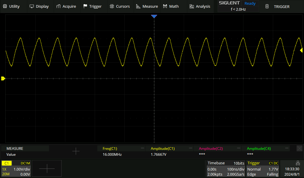
I suspected the chip having no clock, because in your screenshot there are no DDS-frequency related measurement values at all. The reading of the temperature might be clocked by the i2c bus alone.

#7712595
Rate this post
useful
not useful

Did you click on "Program Device Registers"?

Yes I did, but "Start Sweep" is still greyed out.
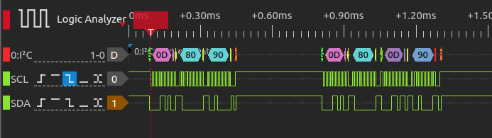
Meanwhile I started to rework the board. I cut the I2C lines and connected it to a ESP32 with this Arduino-Example and modified it a little bit:
https://github.com/mjmeli/arduino-ad5933
I can read the temperature and I get also some measurements. They are wrong but stable when place a 100k resistor in the RFB pins and some DUT resistor. Now I have to find out how to setup the resistors on the board.

#7712643
Rate this post
useful
not useful

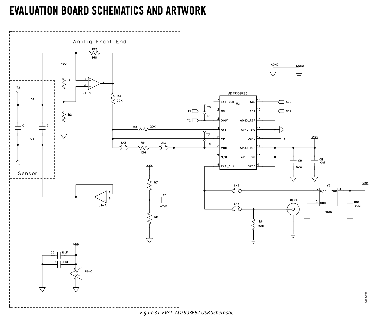
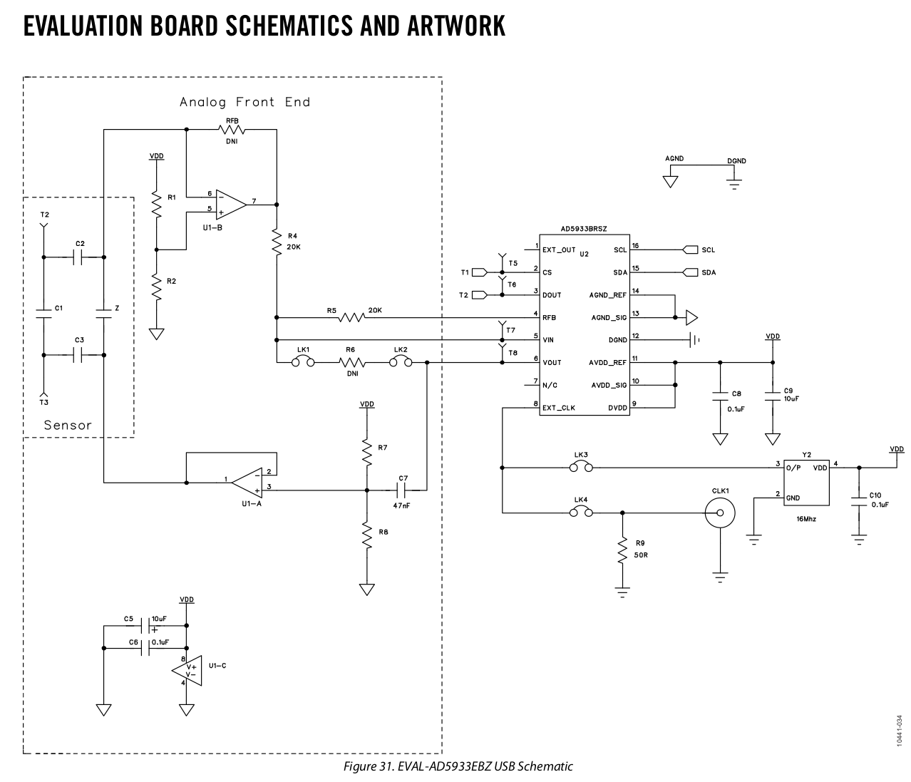
Without digging deep into the datasheet I connected 10k as RFB and 10K as "device under test" (schematic: https://embdev.net/attachment/642119/AD5933_EvalSchematic1.png ) . The measurement is done with the Code above. The result looks strange. Someone has an idea?

#7714377
Rate this post
useful
not useful

Hi again,

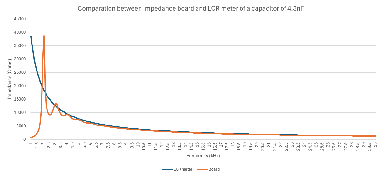
So I have been trying to compare my data with the LCRmeter, now I have the behavior of the attach chart. I have almost the same but the first points are not really matching.

To try it I´m using a capacitor of 4.3nF as my DUT, a gain resistor of 1K on my AD5933.

Thanks! Daphne

Attached files:
#7714443
Rate this post
useful
not useful

What measurement setup of the AD5933 are you using?
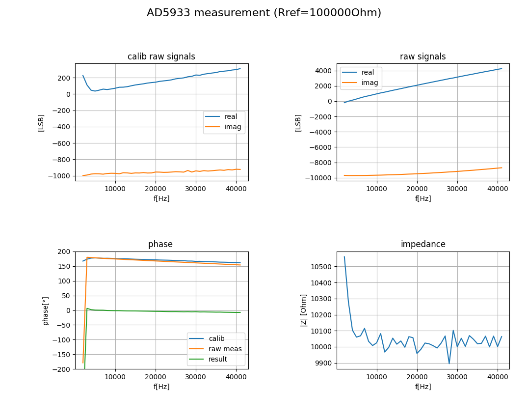
My setup is a AD5933 eval board on which I had to place a gain resistor RFB of 10k.
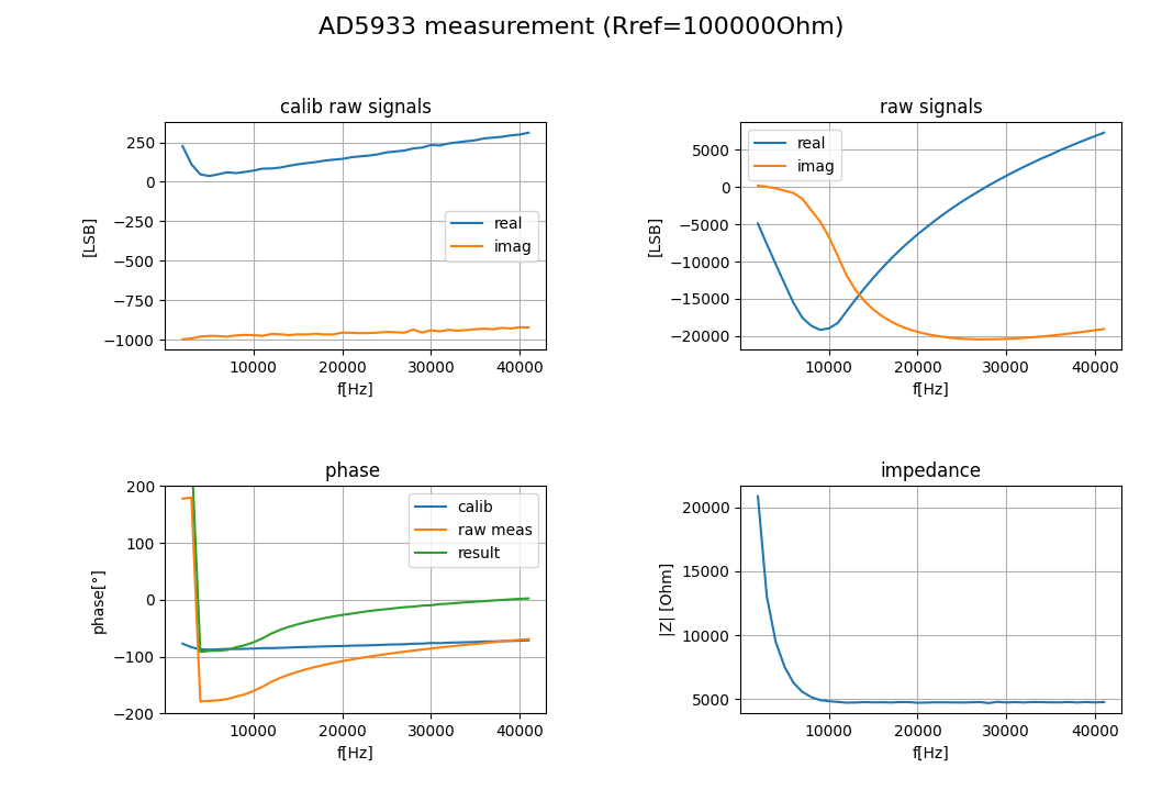
In the attachment you can see the measurement of a 10k resistor. The calibration was done with a 100k resistor.
At lower frequencies (<2000Hz) there seem to be accuracy problems with the eval board amplifier.
If you want to know the phase calculation, take a look in the python code attached.

#7714633
Rate this post
useful
not useful

I had to correct my phase calculation. The arctan2 requires the imaginary part first. Anyway: for a pure capacitor the phase should be fixed at -90 degrees. The measurements with the eval board show only for low frequencies -90 degrees.

1
phase=np.arctan2(imag,real)/np.pi*180
2
phasec=np.arctan2(imagc,realc)/np.pi*180 #callibration
3
magnitudec=np.sqrt(realc*realc+imagc*imagc)
4
magnitude=np.sqrt(real*real+imag*imag)
5
gain=1/(Rref*magnitudec)
6
impedance=1/(gain*magnitude)
#7714657
Rate this post
useful
not useful

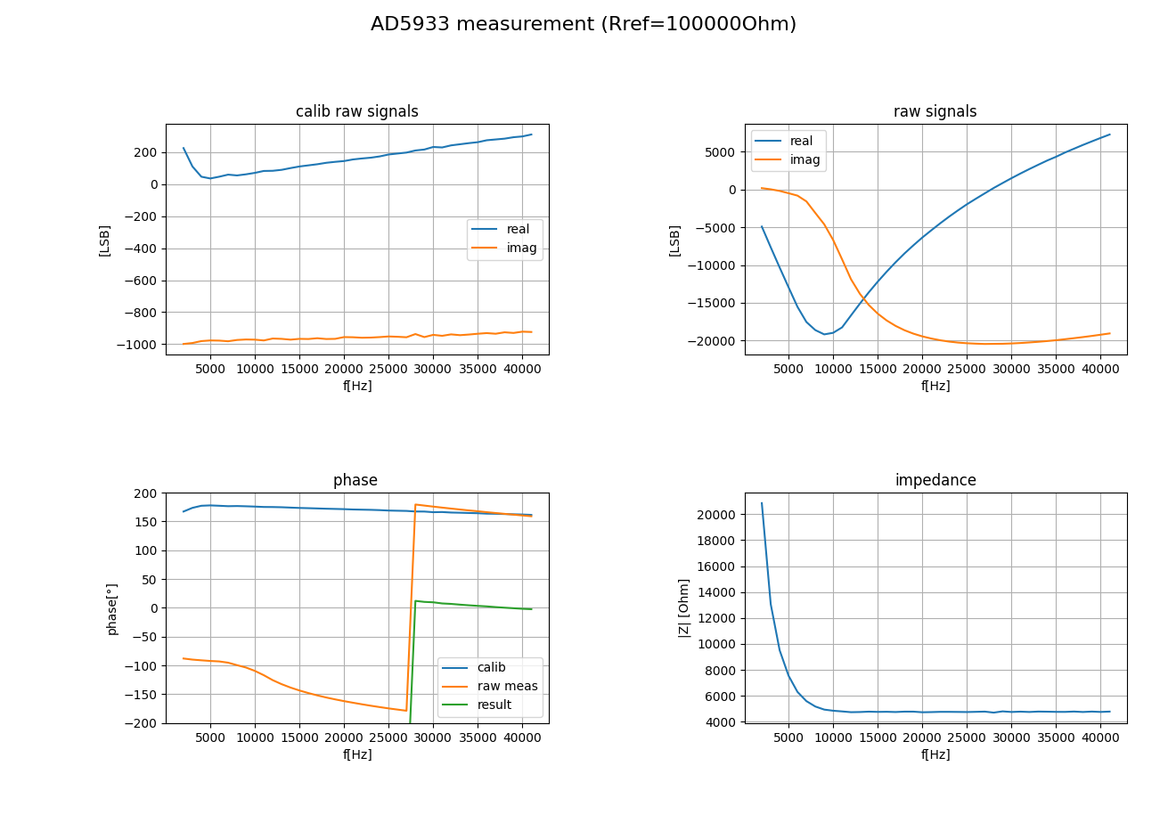
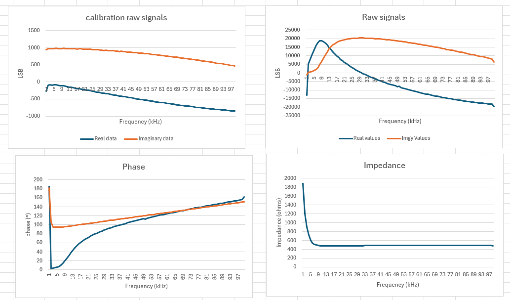
So, I wanted to try my board and I use the same values that you use, Rfb 10K, calibration of 100k resistor.

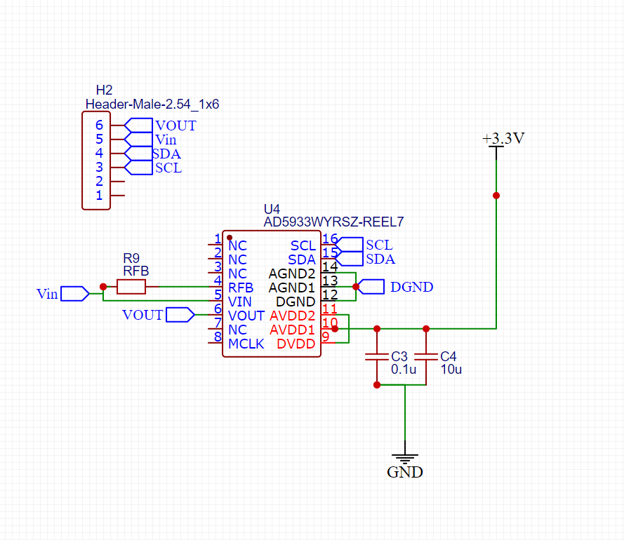
And I realize I have the signals flipped, I attach the picture of my obtained data, I am not using the evaluation board but the chip and I created a small PCB like the connection diagram that I attach too.

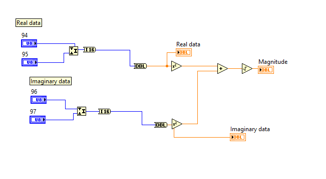
I don´t have any clue of why my data is flipped, I am reading for the real data the register x94,x95 and for the imaginary data register x96 and x97. I also attach a picture of how I´m transforming the data.

Thanks Daphne
#7714739
Rate this post
useful
not useful

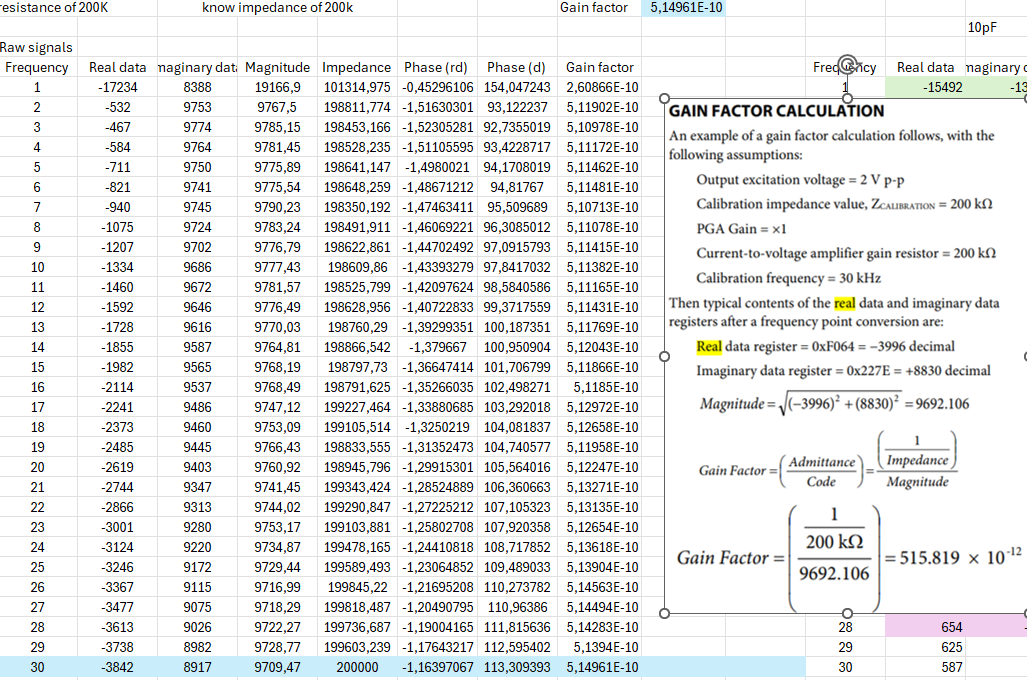
Hi again, I´m really confuse now I did try to check if I was messing up the obtained data, that maybe somehow I was flipping the sign or so. Therefore I check one example to obtained the gain factor.

Just to clarify I have been calibrating my system, this was just to check if the data I was getting was having the right sign. And It looks like I do, also I did the next one with the 510k impedance and I also got the real and imaginary data really similar to the datasheet so I´m more confuse now.

Also here I´m using as mentioned in the picture a 200k impedance calibration, 200k RFB, PGA gain x1.

Attached files:
#7715114
Rate this post
useful
not useful

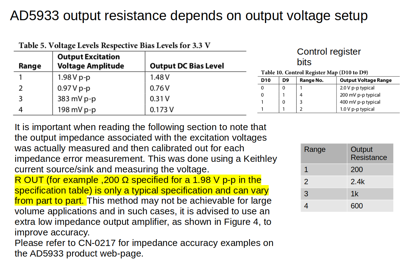
Your PCB uses the AD5933 without any external amplifier. In its basic form it has a relative high output resistance which I would think it adds to the impedance of the DUT.

The output resistance when the output voltage is set to its maximum with the configuration register is regarding the datasheet 200Ohm. This would explain 200Ohm of the 500Ohm of your measurement at higher frequencies here:
https://embdev.net/attachment/642492/Measurement_with_capacitor_4.3nF.PNG

There is an application note CN0217 on the accuracy of the AD5933:
https://www.analog.com/en/resources/reference-designs/circuits-from-the-lab/cn0217.html#rd-evaluationNtest

Probably you can post a picture of your hardware and the DUT, to see if it is probably also

Attached files:

Reply

Please log in before posting.

or

Log in with Google account

Registration is free and takes only a minute.

Register now