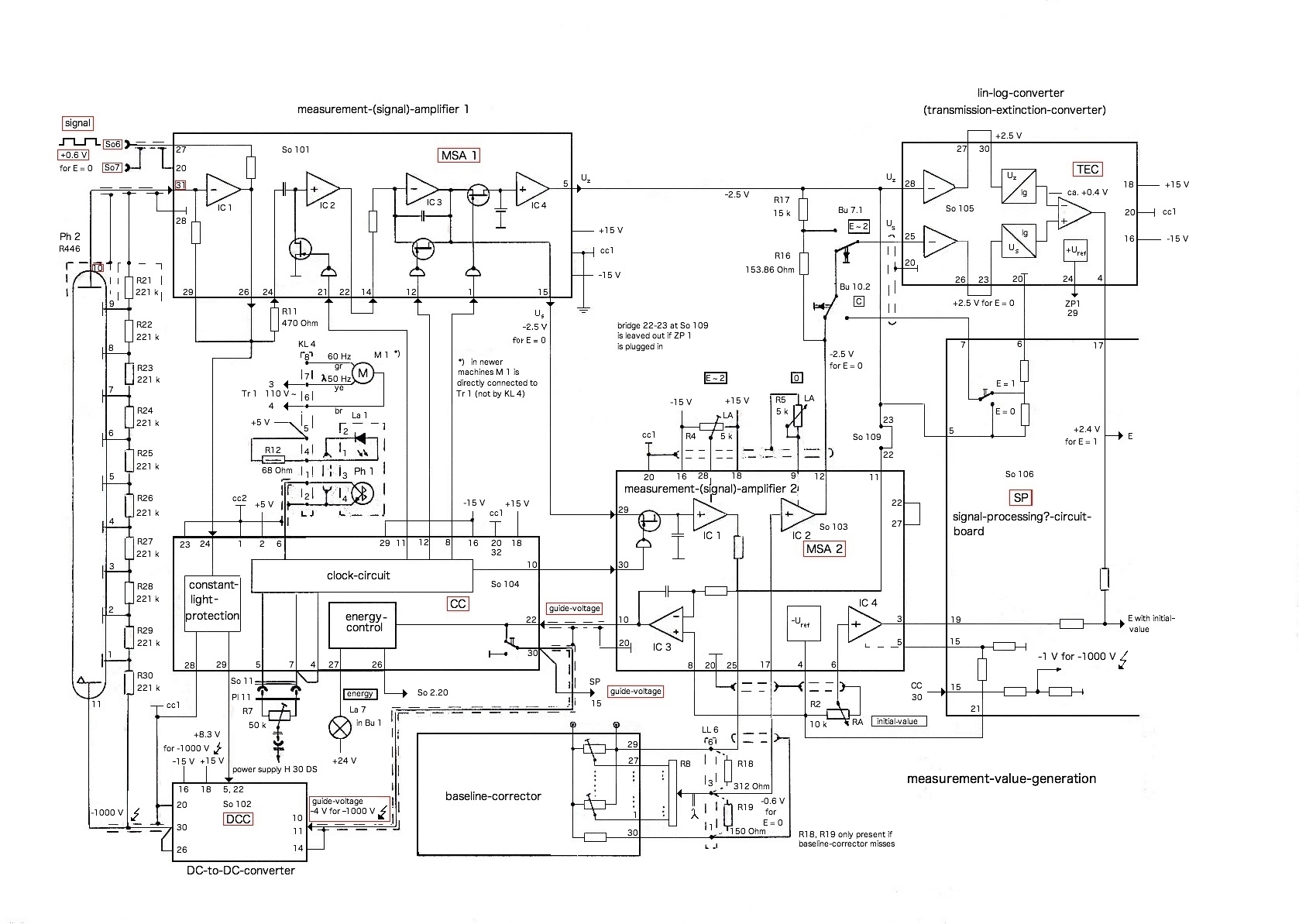
Hello,

it is about troubleshooting and repair of a double-beam-photometer.

The photometer has three failures.
1. the measurement value is quite strongly fluctuating.
2. the measurement value (without sample) should be E = 0.000 but
instead of it quite strongly fluctuates around E = 0.300 (E = 0.24_ -
0.35_).
3. when measuring samples:
the higher the concentration the lower is the measured value, the
opposite of what it normally should be!

First of all I am only interested in solving failure number one!

To locate the failure I need advice because I am not an
electronics-expert!

1. circuit diagram:
https://www.file-upload.net/download-15154708/measurement-value-generation.jpg.html

Question 1: Is the direct (output voltage) signal from the
photomultiplier tube a correct pmt-signal?
2. pmt-output-voltage-signal:
https://www.file-upload.net/download-15154693/pmt-output-signal.mp4.html
setting: 50 mV/div and 5 ms/div.

The photometer normally should have a rectangular signal of U = +0.6 V
for E = 0 but it strongly fluctuates around 2 V - 2.5 V (for E ≈ 0.300).
3. signal:
https://www.file-upload.net/download-15154698/signal.mp4.html

4. guide-voltage:
https://www.file-upload.net/download-15154705/-4V_guide_voltage.mp4.html

5. pmt-high-voltage:
https://www.file-upload.net/download-15154706/-1000V_high_voltage.mp4.html


I am no electronics-expert but I think possible reasons for fluctuation
of the signal/measuring-value could be:
1. unstable guide-voltage
2. unstable pmt-high-voltage
3. pmt-defect
4. other

Thank you!
Attached files:
First you should find an oscilloscope and a high voltage voltmeter. As a
first step make sure that all power supply lines give constant DC
voltage without fluctuations. Measure the PMT supply with the high
voltage voltmeter or a HV probe for the oscilloscope.
Continue by verifying the waveforms shown in the diagram and measure the
voltages shown. Start with the frontend amplifier and continue with the
Sample & Hold stages and the lin/log converter.

Pin 6 of the Clock Circuit (CC) should carry the signal from the
interupter wheel and it should be close to a square wave. Without this
signal the whole circuit will not work properly. It clocks the S&H
switches and so the amplifiers MSA1 and MSA2.
Hello Matthias,

thank you very much, your advice has already helped me much!

I have got an analogue-oscilloscope with a HV/HF-probe up to U = 2500 V
but no high-voltage-voltmeter. There is a table of almost all possible
values that I measured yet and I am going to remeasure some values first
of all particularly pin 6 of CC because the first value of pin 6 CC that
I looked up is U = 0.4 - 0.6 V!

Last time the video-links did not work therefore here are new working
links!

Videos of clock-circuit (CC)-signal measured at pin 6:
settings:
• 0.2 V/div and 5 ms/div
• 0.2 V/div and 2 ms/div
• 0.2 V/div and 1 ms/div
• 0.5 V/div and 5 ms/div
https://workupload.com/archive/7G9LeYrjjH

Question 2:
Is this a good signal? I don't think so!

2. pmt-output-voltage-signal:
setting: 50 mV/div and 5 ms/div.

The photometer normally should have a rectangular signal of U = +0.6 V
for E = 0 but it strongly fluctuates around 2 V - 2.5 V (for E ≈ 0.300).
3. signal:
setting: 1 V/div and 5 ms/div

4. guide-voltage:
setting: 1 V/div and 5 ms/div
5. pmt-high-voltage:
setting: 200 V/div and 5 ms/div
https://workupload.com/archive/KPTzue9YDX

Thank you!
Looking at the circuit this is anything but a good output from the
phototransistor. The level is much too small and there's a signal with
it which doesn't look like the expected clean squarewave.

To see if its a issue with the supply of the CC, it might be a good idea
to stop the motor and turn the interrupter by hand if that is possible.
The output should jump between high and low.
No light except the LED should light th phototransistor. Use the
oscilloscope to verify the supply voltages of the CC and make sure it's
a clean DC voltage, for both +15 and -15V and of course the 5V.

If the output of the phototransistor is still this low check the LED.
Older LEDs tend to loose brightness over time and it might be the case
here. If possible, use another lightsource next to the LED while
measuring Pin 6.

If the unit is a complete forked photoelectric sensor, it might be best
to replace it.
Hello Matthias,

first of all thank you very much once again!

I am still busy with remeasuring and to put in order the data material
and writing it down.

I will report to you as soon as possible. Probably tomorrow.
Hello Matthias,

I am back again; sent you a personal message.


Here are a few remeasured values.


The operational voltages of the clock-circuit (CC) with different
settings:
pin 16: U = -15 V

pin 18: U = +15 V

pin 2: U = +5 V

pin 25: U = -15 V

pin 26: U = +5 V

pin 31: U = +5 V

pin 6: presumably phototransistor

https://workupload.com/archive/WwJ5hdHdhL


Unfortunately I have forgotten to make films of pin 26! They will follow
soon.
Its not very helpful to show movies of an oscilloscope only showing a
straight line. If the voltage has no humming or other noises its ok.
I suspect that you are not very familiar with electronics but you have
to find something near you who is.
The usage of photometer leads me to think that you are in a scientific
environment and surely there must be someone who can help on location.

What you really need to find out is if the level of the phototransistor
output is sufficient to clock the Clock Circuit. And i can't identify
any phtotransistor in the supplied picture. There must be a motordriven
interrupter wheel and an LED/Phototransistor combination which is
interrupted by the wheel. This signal is used to clock the amplifiers
and sample&hold stages with the help of the Clock Circuit CC.
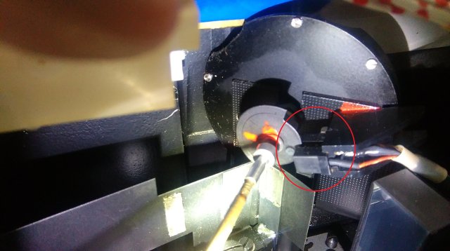
Hello Matthias,

thank you very much. Until now you have helped me very much yet and I
know what is to do next.

Sorry, I didn't want to bore you but I didn't know if the slight
fluctuation of the line is normal. From now on I know it.
> I suspect that you are not very familiar with electronics but you have
> to find something near you who is.

I am an electronics newcomer.
That is not so easy.


> The usage of photometer leads me to think that you are in a scientific
> environment and surely there must be someone who can help on location.

That is right.
But even that is very difficult.

> What you really need to find out is if the level of the phototransistor
> output is sufficient to clock the Clock Circuit. And i can't identify
> any phtotransistor in the supplied picture. There must be a motordriven
> interrupter wheel and an LED/Phototransistor combination which is
> interrupted by the wheel. This signal is used to clock the amplifiers
> and sample&hold stages with the help of the Clock Circuit CC.

Ok I have fully understood. I have to find the LED/phototransistor
combination and must then measure the phototransistor output level. This
is the absolutely essential next step for troubleshooting!

The interrupter wheel/chopper (light beam divider) is in the optical
system case.
Here are two photos of it:
https://workupload.com/archive/9f9RssHQR9

The phototransistor should be near the chopper case. I hope I will find
the phototransistor because it is difficult to look and handle in the
optical system case!
Matthias S. wrote:
> i can't identify any phtotransistor in the supplied picture

Ph1 is direct under La1 and Motor M. Signal is on Line 6, it has
probably high impedance, so use a 10:1 probe when measuring with
oszilloscope, even if signal level is small. Ground level is on line 1
and 23. Signal is also available on KL4-1, Gnd on KL4-2.

If the clock-circuit is working, there must be the chopper signal on
Line 8, 10, 11 and 12 with digital level.
Hello Wolf,

thank you very much for your help!


Matthias means photo by picture that I have sent here:
pin 6: presumably phototransistor

https://workupload.com/archive/WwJ5hdHdhL

Now I have finally understood that by La 1 (lamp 1) is meant a LED and
namely the one LED which feeds phototransistor Ph 1 with light pulses
that are generated by the chopper.

The next thing I have to do today is to search for KL 4, La 1 and Ph 1;
hope I will find them!

When I first studied the circuit diagrams I didn't know what meant "Ph
1". I couldn't find the circuit symbol because it is an outdated one. A
little bit later it was clear to me that it must be a phototransistor
but its function wasn't clear.
Thanks to Matthias I know now!

No idea I had that my photometer needed a phototransistor to work. I
have always thougt:

light source ---> chopper chops/divides the light beam --->
photomultiplier tube ---> signal amplification and processing --->
output to display ---> ready! (process is highly simplified and
abbreviated)

I have to say that I understand my machine better and better.
Alois wrote:
> pin 6: presumably phototransistor
>
> https://workupload.com/archive/WwJ5hdHdhL

Yeah, i saw that but can't find any phototransistor there. I see a
measuring point at the end of a 2k21 resistor. The funny loop is for
clipping a probe onto it.

Alois wrote:
> The next thing I have to do today is to search for KL 4, La 1 and Ph 1;
> hope I will find them!

Those must be close to the chopper motor where the light beam of the LED
is interrupted by some kind of iris or so. The base clock of this signal
is then used to switch between the two MSA blocks and is also
responsible for switching the corresponding Sample & Hold circuits. in
the meantime between measurements this circuit holds the last sampled
value for evaluating. As this is a double beam photometer, the circuits
are used in an alternating mode, one circuit for each beam, selected by
the chopper.
Alois wrote:
> The next thing I have to do today is to search for KL 4, La 1 and Ph 1;
> hope I will find them!

To find KL4, search for the motor, probably you can hear him working.
Follow the shaft until you find the rotating segmented shutter wheel.
Look for the 68R resistor, it is lokated from KL4-4 to KL4-5. The
voltage at the 68R should be about 3Vdc.

According to the schematics, they have used a LED as lightsource. Look
if you can see some (red?) light if it is dark in the room. Maybe they
use a invisible IR LED. Maybe they use a beam enclosure or a fork light
barrier like this:
https://cdn-reichelt.de/bilder/web/xxl_ws/A500/ELI_TR8102.png
Hello Matthias and Wolf,

thank you both very much. This is a very big and great help and
motivation for me!

Unfortunately my search was only partially sucessful. What I think I
have found is the phototransistor but not the LED, KL 4 and the 68 kOhm
resistor.

Here are some photos of presumably Ph 1 and other:
1. presumably phototransistor Ph 1, img 1
2. presumably phototransistor Ph 1, img 2
3. fixation screw of presumably Ph 1
4. chopper motor and transformator Tr 1, img 1
5. chopper motor and transformator Tr 1, img 2
6. transformator 2? pins:
I think this cannot be KL 4!

https://workupload.com/archive/Zyh2FN8wUh
Attached files:
-

FjpHAVEz9Wn.jpg
40 KB
Well, that was easy. I marked the forked interrupter in the photo. Its
fork contains the LED on one side and the phototransistor in the other.
With each turn of the wheel the beam is interrupted for half a turn. On
the other half turn it passes and the phototransistor is lit.

From other components of this type i think the output level of the photo
TR in your system (approx. 0.2V) is too low. I'd expect more than 2V.

Here's a picture of a CNY36, resembling very closely what you have
there:
https://www.muekra.de/cny36.html
Alois wrote:
> 3. fixation screw of presumably Ph 1
Following the thick black cable comming out of the forked interuptor
will bring you to KL4 and the 68 Ohm resistor.
Hello Matthias, hello Wolf,

thank you very much. Your help is just great class. You are a good team!

I will order the replacement part and install it.

> Its fork contains the LED on one side and the phototransistor in the other.

Secretly I have already suspected that but I did not want to disgrace
myself.


> Following the thick black cable comming out of the forked interuptor
> will bring you to KL4 and the 68 Ohm resistor.

As a reminder:
*) In newer machines M 1 is directly connected to Tr 1 (not by KL 4)!

The black cable disappears into the "underground" through a hole of the
optical system housing but in the next few days (before I get the
replacement part) I will try to find KL 4 and the 68-Ohm-resistor, i.e.
I will follow the black cable.

https://workupload.com/file/XSMMCaCznDk

After that, I will get back to you and report further.
Hello,

I am back again. Sorry I was busy with obligatory tasks!

The optocoupler arrived long ago!

I don’t know how the optocoupler is fixed to its mounting and therefore
how to remove it. There are two screws, one with a counter nut in
direction of the cables, function unknown. Perhaps it is a spacer? When
I loosened this screw I could not remove the optocoupler (plastic) or
its fixture. The second screw is orthogonal to the first one. I think it
only fixes the optocoupler mounting on the metal housing of the
chopper-mirror wheel.

https://workupload.com/archive/zRx3HNEa3q

Perhaps the optocoupler may be inserted into the optocoupler mounting so
that you have to pull it out backwards to remove it?

Hopefully it is not glued!

What function does the red colour have? Is it used as a marker?
Are you sure the optocoupler is defective?
What is voltage across R12? Did you measure Ph1 output signal like
suggested? Result? Did you check chopper signal lines?
Wolf17 wrote:
> Did you measure Ph1 output signal like
> suggested?

Yeah, theres only a signal with 0.6 Volts on the input of the Clock
Circuit. I assume that this is much too low to trigger the circuit.
Alois wrote:
> Videos of clock-circuit (CC)-signal measured at pin 6:
> settings:
> • 0.2 V/div and 5 ms/div
> • 0.2 V/div and 2 ms/div
> • 0.2 V/div and 1 ms/div
> • 0.5 V/div and 5 ms/div
> https://workupload.com/archive/7G9LeYrjjH

Sorry, I can not remember the pin 6 video and it is not available
anymore.
How much turns per second makes the shutter wheel?
Hello Wolf and Matthias,

thank you again for reply!


Wolf17 wrote:
>Did you check chopper signal lines?
Which lines do you mean?

Wolf17 wrote:
> Are you sure the optocoupler is defective?
According to Matthias very probably.

Wolf17 wrote:
> What is voltage across R12?
I haven’t measured the voltage at 68 kOhm resistor R12 yet. Then I will
know if the voltage is U(DC) ≈  3 V. Before I haven’t measured this
voltage I will not change the optocoupler. First off all I have to screw
down the photometer housing und then set up the machine because the
cable is at the bottom.

Wolf17 wrote:
> How much turns per second makes the shutter wheel?
The shutter wheel rotates with net frequency, i.e. f = 50 Hz.

Wolf17 wrote:
> Did you measure Ph1 output signal like suggested? Result?
> Sorry, I can not remember the pin 6 video and it is not available
> anymore.

Here are the videos of the clock-circuit (CC)-signal measured at pin 6
once again:
settings:
• 0.2 V/div and 5 ms/div
• 0.2 V/div and 2 ms/div
• 0.2 V/div and 1 ms/div
• 0.5 V/div and 5 ms/div

https://workupload.com/archive/xYtrC25rDq
Alois wrote:
> 0.2 V/div and 5 ms/div

There is a strange ripple each 10ms, please check all supply voltages
with oszilloscope:    +5V at 68 Ohm R12 and +5V +15V -15V at CC.

I want to know the LED current, what is the voltage across the 68 Ohm
R12?

The signal has a roof slope, did you measure with AC coupling instead
with DC coupling?
I can not see if signal is 0 to 0,25V or for example 0,3 to 0,55V. When
making new oszi-video (pictures are enough), please use DC coupling and
adjust beam position for zero Volt signal is exact at middle line.

The signal has steep edges, in principle the optocoupler seems to
switch, only the 0,25V amplitude is a bit low. Is it 2,5V because you
used a 1:10 probe head?

>>Did you check chopper signal lines?
>Which lines do you mean?
2023-06-17 15:46    If the clock-circuit is working, there must be the
chopper signal on Line 8, 10, 11 and 12 with digital level.
Hello Wolf,

thank you very much and sorry for my late reply!

Now I have found the 68 Ohm-R 12-resistor (in real a 65 Ohm-resistor!)
and KL 4 but with another pin assignment, see photo. Until now I haven't
measured the voltage of R 12 and the phototransistor Ph 1 firstly
because I don't know if the power unit of the interrupter wheel/chopper
(driving shaft or chopper motor) of my photometer will be damaged when
measuring while it is standing lateral upright and secondly because I
have to know how to measure in detail.

Here is the pin assignment:
Left side: resistor R 12 and LED connections?
pin 1/socket 1: mass (grey cables are mass (ground?) cables in this
machine)
pin 2/socket 2: a thin black cable
pin 3/socket 3: resistor R 12 (65 Ohm)
pin 4/socket 4: resistor R 12 (65 Ohm) and red cable
pin 5/socket 5: –
pin 6/socket 6: –
pin 7/socket 7: –
pin 8/socket 8: –

Right side: phototransistor Ph 1 connections
pin 1/socket 1: black cable
pin 2/socket 2: copper-coloured cable, black curled
pin 3/socket 3: copper-coloured cable, red curled
pin 4/socket 4: –
pin 5/socket 5: –
pin 6/socket 6: –
pin 7/socket 7: –
pin 8/socket 8: –

I suppose that red is plus and black is minus as usually.

Questions:
1. What is the black cable of pin 1/socket 1 (right side) for?
2. Is the red cable of pin 4/socket 4 (left side) the supply voltage U =
+5 V?
3. Probe at pin 4/socket 4 (left side) gives the supply voltage of U =
+5 V, i.e. before passing resistor R 12 and probe at pin 3/socket 3
should give U ≈ 3 V DC after passing resistor?
4. How to measure Ph 1? Is it correct, probe at red cable?


Matthias wrote:
> To see if its a issue with the supply of the CC, it might be a good idea
> to stop the motor and turn the interrupter by hand if that is possible.

Now I know that unfortunately the chopper motor M is not connected by KL
4 (pins 7 and 8) but directly to transformer Tr 1. Therefore, I would
have to unsolder a pin of the chopper motor to stop the interrupter
wheel without causing a possible damage of the power unit (driving shaft
or/and chopper motor) instead of in case of stopping the interrupter
wheel by hand!


I have sent following things:
1. Photos of KL 4 with R 12, pins of LED? and Ph 1
https://workupload.com/archive/5wYc6aYHjT

2. Voltage measurement values of CC
Wolf17 wrote:
> Signal is on Line 6, it has
> probably high impedance, so use a 10:1 probe when measuring with
> oszilloscope, even if signal level is small.
Setting of probe: always 1:1-position.

Wolf17 wrote:
> The signal has a roof slope, did you measure with AC coupling instead
> with DC coupling?
I measured with DC coupling, see below!

Wolf17 wrote:
> I can not see if signal is 0 to 0,25V or for example 0,3 to 0,55V. When
> making new oszi-video (pictures are enough), please use DC coupling and
> adjust beam position for zero Volt signal is exact at middle line.
Both DC switchers were and are in DC position and this time zero line is
in middle position!

Wolf17 wrote:
> The signal has steep edges, in principle the optocoupler seems to
> switch, only the 0,25V amplitude is a bit low. Is it 2,5V because you
> used a 1:10 probe head?
No, I have always measured in 1:1-position.
Once I have measured the signal with that 1:10-setting (without making a
photo) but it gave a worse value. After reopening the photometer housing
I will make a second measurement together with a photo which I will send
then!

clock-circuit:
pin 2, supply voltage: U = +5 V
pin 16, “ : U = –14.95 V
pin 18, “ : U = +14.95 V
https://workupload.com/archive/g7Hd2H7PrE

pin 8, clock/chopper/interrupter wheel-signal: U ≈ +3.8 V
pin 10, “ : U ≈ +3.8 V
pin 11, “ : U ≈ +3.8 V
pin 12, “ : U ≈ +3.8 V
https://workupload.com/archive/V4SQdcvfdn

pin 4, clock/chopper/interrupter wheel-signal: U ≈ +3.8 V
pin 5, “ : U ≈ +3.8 V
pin 6, “ : already known, U ≈ 0.4 – 0.6 V
pin 7, “ : U ≈ +3.9 V
https://workupload.com/archive/J4apHAkbSV

constant-light-protection:
pin 24, signal from MSA 1: U ≈ 2 V?, Parkinson-like
pin 29: U ≈ 8.8 V instead of U = 8.3 V
https://workupload.com/archive/cYHuvhdFLH

energy-control:
pin 22, outgoing guide-voltage: U ≈ –4.2 V
pin 30, incoming guide-voltage: U ≈ –4.2 V
pin 26, supply voltage: U = +5 V
pin 27, energy-control voltage: U ≈ 32 V instead of U = 24 V?
https://workupload.com/archive/ktt4mm7Xt2

3. Circuit diagramm of CC
https://workupload.com/file/K74apZC5Unk

4. Photos of CC-circuit board
https://workupload.com/archive/JMqQfAQndr

5. Videos of digital voltmeter counter unit-circuit board (DVC) voltage
measurements
Photos:
https://workupload.com/archive/SCEQFEhMHW
Videos:
https://workupload.com/archive/VNbbykpejM

I suppose the steady jumping signal voltage of pin 26 and pin 32 should
be the same for the other pins. This shows the faulty signal!

6. Overview circuit diagramm of measurement-value-processing. Follows
later! It is needed to (better) understand the videos of 5.
Thank you for CC circuit.
Even if pin 6 signal look not perfect, the clock-circuit output 4 5 7
and 8 10 11 12 are good. In my opinion, optocoupler and CC digital
output signals are working as intended.
Hello Wolf,

thank you very much!

despite a slight risk of damaging my machine I decided to measure the
voltage of La 1 (LED) and signal of Ph 1 (phototransistor) at KL 4.
1. Supply voltage R 12: U = +5 V
2. La 1/LED: U ≈ +1.25 V
3. Signal of Ph 1: U ≈ +0.2 - +0.6 V, rectangular
4. Signal of CC-6 for comparison
5. Voltage of R 12: not measured
6. Current-voltage characteristic of R 12 before LED destruction
https://workupload.com/archive/hXud6eQxAE

Because of inattention in measuring the current-voltage characteristic
of R 12 I destroyed the LED of the clock. I accidentally forgot to turn
off the photometer before measuring resistor R 12!
Values after destroying:
1. Supply voltage of R 12/LED: U = +5 V, unchanged
2. La 1: U ≈ +4.25 V
3. Signal of Ph 1: U ≈ +0.6 V, not rectangular any more, i.e. flat line
4. Voltage of R 12: not measured
5. Current-voltage characteristic of R 12 after LED destruction
https://workupload.com/file/yAah9XGwcfp

In the meantime, I have ordered an original replacement clock to avoid
problems and to make sure that everything is working correctly because
it is a special design with integrated cables and a special optocoupler
(opt.) plastic housing which only fits to its fixture. The two bought
cny36-opt. exemplars do not fit anyway!
https://workupload.com/archive/Xhu6n9xFn5


As expected all voltages which need a correctly working clock are
affected. For example:
1. CC-8, 10, 11, 12: correct voltage values but now flat lines
2. CC-29: U = 0 V instead of +8.8 V
3. CC-10, 22, 30, guide voltage: U = –6.2 V instead of –4 V
4. DCC-10, 11, guide voltage: U = –6.2 V instead of –4 V
5. DCC-30, high voltage: U = 0 V instead of –1000 V

Then I took my torch and illuminated the LED, whereupon nearly all
values normalized, i.e. flat voltages are digital again, high voltage is
U = –700 V and guide voltage is wandering from U = –6.2 V to a less
negative value.
• CC-6, signal of clock illuminated with torch, 1 V and 1 ms:
https://workupload.com/archive/zpQC29G2dy

After installation of the clock and measuring I will further report.
Hello,

the first repair trial failed. Paradoxically, although everything seems
to work correctly it does not work correctly. I don’t know what the
problem is at all!

Here are some photos and and a video of the clock LED and clock
phototransistor:
1. Characteristic curve, original defective LED La 1, clock built-out
2. Characteristic curve, replacement LED, clock built-out
3. Characteristic curve, original phototransistor Ph 1, clock built-out:
the same as 4.
4. Characteristic curve of replacement phototransistor, clock built-out
5. Characteristic curve of replacement LED, at KL 4-4/KL 4-2, clock
built-in
6. Supply voltage of resistor R 12/replacement LED at KL 4-5
7. Forward voltage of replacement LED at KL 4-4
8. Signal of replacement photoresistor at KL 4-1
9. Characteristic curve of resistor R 12 at KL 4-5/KL 4-4, clock
built-in

https://workupload.com/archive/LgvRSFpGmv

Maybe the resistor is damaged from my faulty measurement. To solve the
problem, my idea would be to remove the supply voltage (including
resistor R 12) and the optocoupler to detect the fault, isolate it and
test CC at the same time. It should be possible to feed in a suitable
square wave signal with U = +0.6 V and the correct current using a
signal generator. I think that would be the most direct, fastest and
best way to proceed.

How does an overdriven phototransistor actually react?
Please log in before posting. Registration is free and takes only a minute.
Existing account
Do you have a Google/GoogleMail account? No registration required!
Log in with Google account
Log in with Google account
No account? Register here.