Hello everyone, I designed a uart successfully.
I initially configured it to enable sending information by a button from
the FPGA, the information was sent successfully.
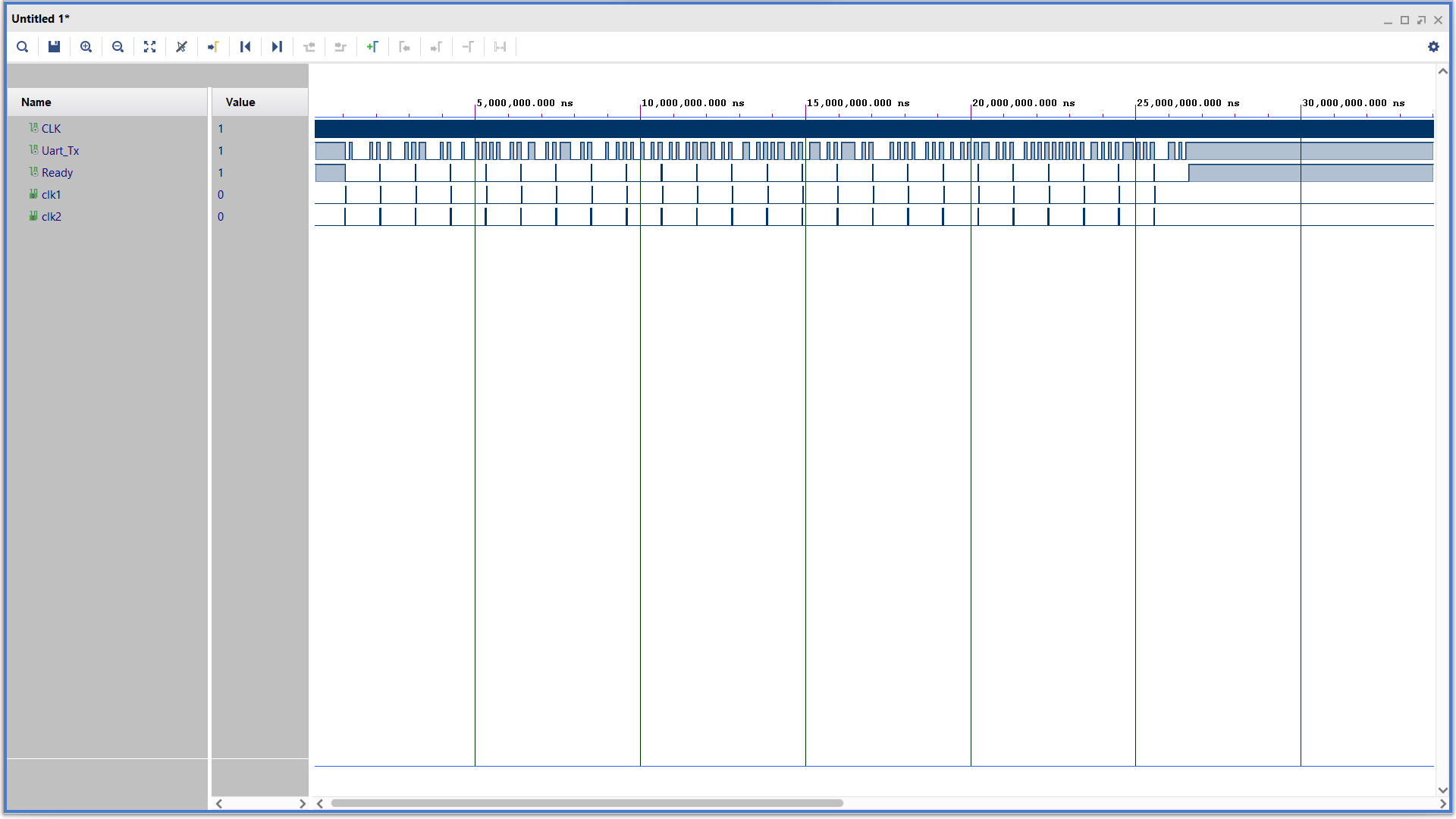
After this I designed a timer that will send 24 packets of 8 bits and
after that it will stop.
Despite this, the system does not stop sending, even though the
simulation is functioning properly in reality, the UART continues to
send information.
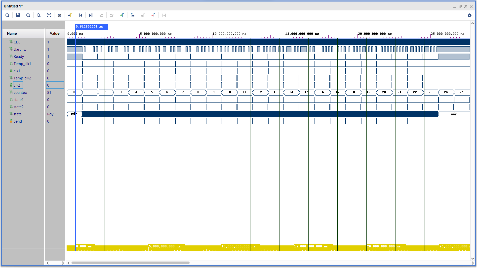
If you notice - in the category of Synchronize the change to signals is
limited to 23 and then the system should stop changing the sending
signals :
if(counteo <= 23 ) then
Temp_clk2<=not(Temp_clk2);
else
Temp_clk2<='0';
end if;
Hello,
your urgent request has been noticed.
Please put on the Warnweste and the Dreieck on the street and hold the
line for additional questions.

Ersthelfers will arrive later this evening.
So ... it's a pity. you master this complicated language but fail at the
simplicity of VHDL.

Why do you not even try to format your code in a readable manner? Use
spaces, use linefeed carrage return and space. They all were invented in
the analog days centurys ago.

But the biggest problem here is:
You postet three components, but the toplevel or binding component is
missing. A testbench is missing, too.

So at the moment the possible error may reside in these missing
components.

Best regards,
-gb-
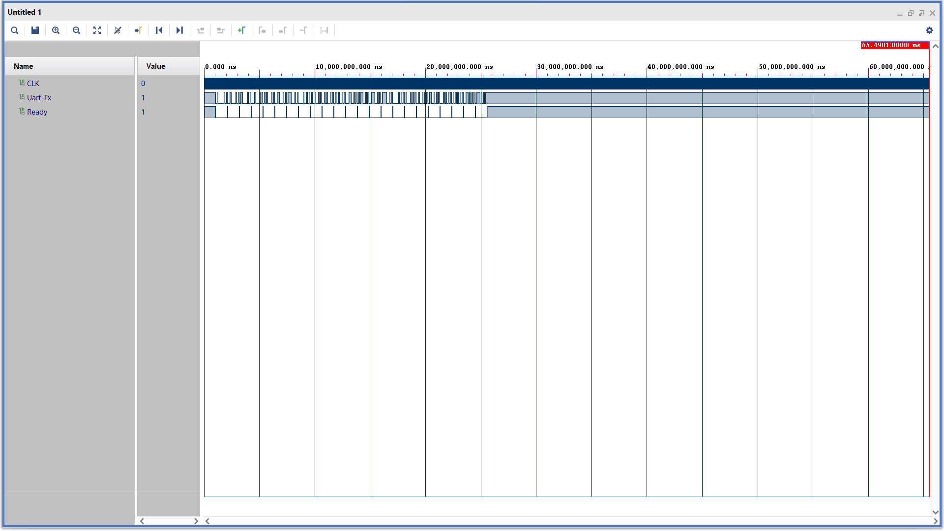
My guess: counteo overflows and so it is <23 again. Let the simulation
run a bit longer and also add the relevant signals (FSM states and all
the different counters, not only the ports) to the waveform.
Sorry, that's not the intention, I built a system that blocks the
sending signal to the uart called Synchronize, which provides 2 signals
- the first is an exchange of the information being sent, and the second
is a sending enable signal - clk1 The uart receives the signal and sends
the information as can be seen in the simulations after 24 times the
signal remains low despite the computer Unlike the simulation, the
information continues to be sent endlessly
FPGA Rettungsdienst wrote:> Help will arrive soon. The Tatütata is on its way to UnfallstelleHeiner wrote:> @ Daniel>> Attaching a few screenshots without further ado is … quite rude,> especially when expecting help>> - 1
Sorry, that's not the intention, I built a system that blocks the
sending signal to the uart called Synchronize, which provides 2 signals
- the first is an exchange of the information being sent, and the second
is a sending enable signal - clk1 The uart receives the signal and sends
the information as can be seen in the simulations after 24 times the
signal remains low despite the computer Unlike the simulation, the
information continues to be sent endlessly
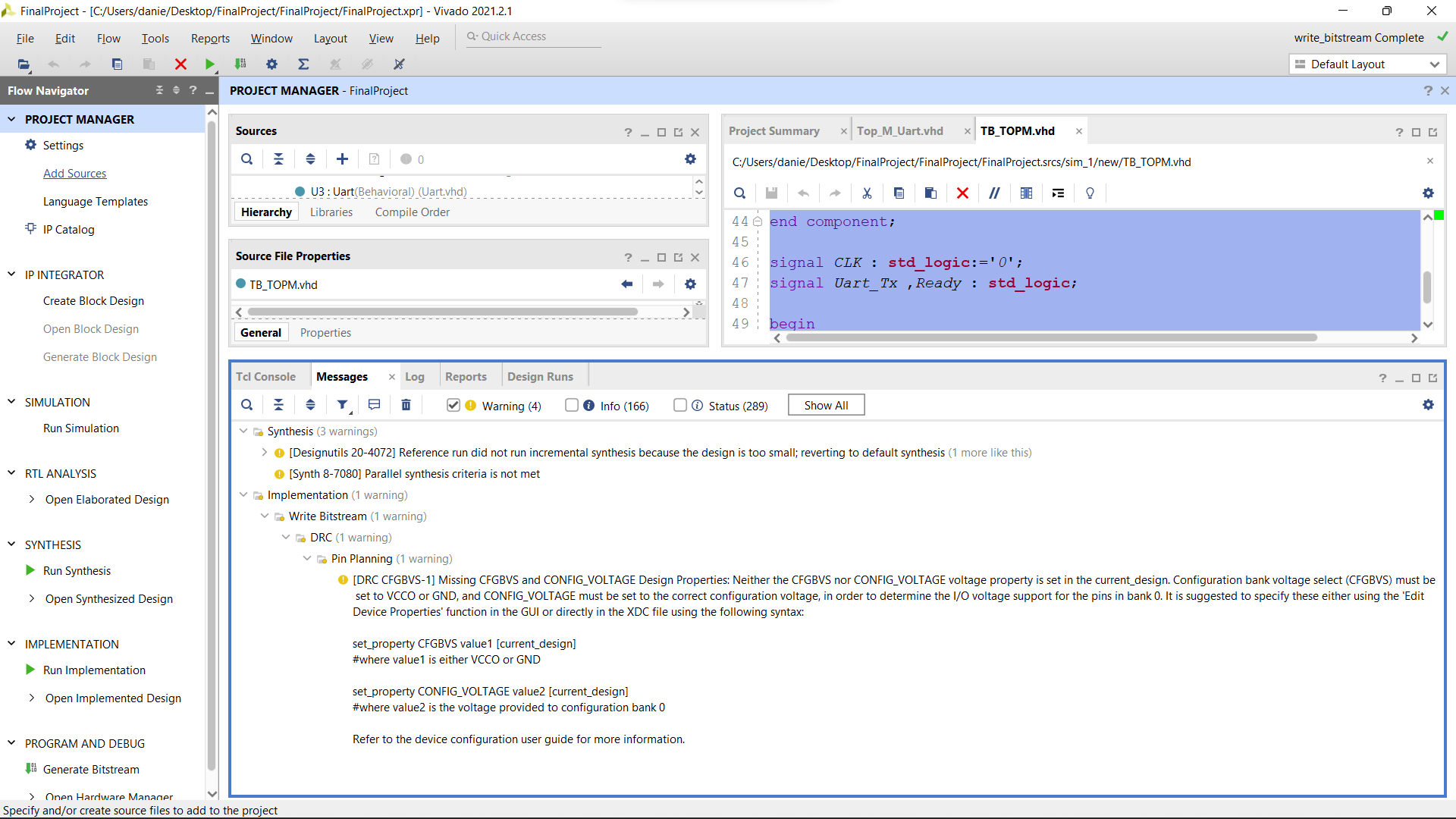
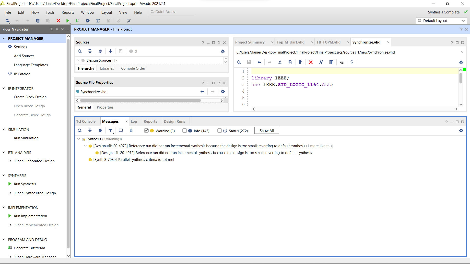
Well the pictures showing the vivado messages are useless because these
messages have nothing to do with your problem.

The simulation pictures are useless as well because they only show the
problem but not the related signals and states inside the problem
causing components.

Notfallhilfe will simulate for you when it arrives at Unfallstelle.
FPGA Rettungsdienst wrote:> Well the pictures showing the vivado messages are useless because> these> messages have nothing to do with your problem.>> The simulation pictures are useless as well because they only show the> problem but not the related signals and states inside the problem> causing components.>> Notfallhilfe will simulate for you when it arrives at Unfallstelle.
I didn't quite understand what I should do in such a case...
The simulation shows 100% normality and in reality the received signals
continue to send the information.
Well,
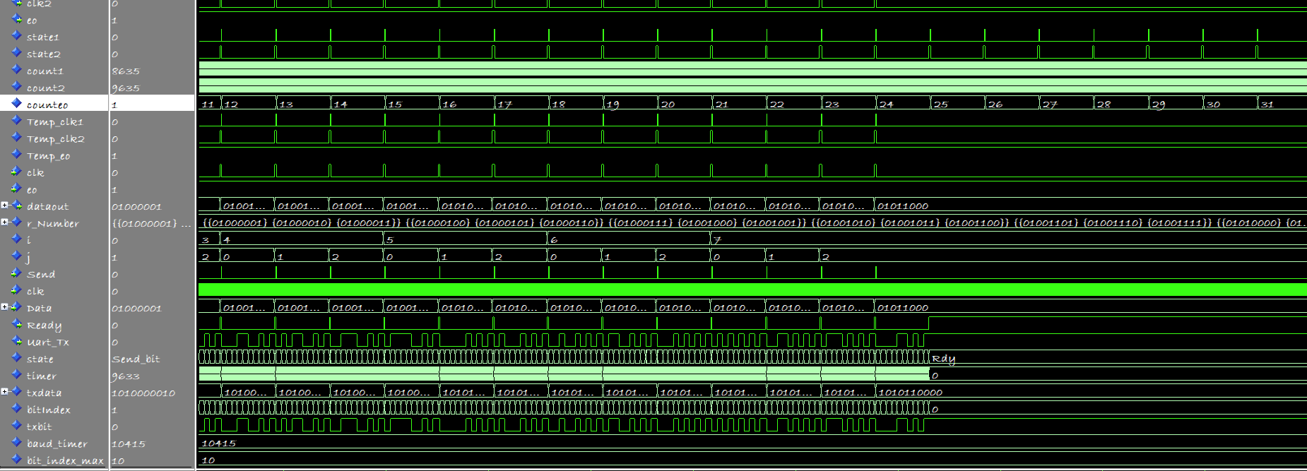
counteo just counts up. It does not stop counting at 23 or 24. So what
will happen?
Helpling wrote:> My guess: counteo overflows and so it is <23 again. Let the> simulation> run a bit longer and also add the relevant signals (FSM states and all> the different counters, not only the ports) to the waveform.
The User was right!
Helpling wrote:> My guess: counteo overflows and so it is <23 again. Let the simulation> run a bit longer
Much longer. This overflow will not happen in feasible simulation time.
But in Hardware it will happen.
FPGA NOTFALLSEELSORGE wrote:> Much longer. This overflow will not happen in feasible simulation time.> But in Hardware it will happen.
Well, counteo is defined as integer range 0 to 50, so the simulator
should give an error in feasible simulation time. In real hardware, the
overflow will take much longer probably, depends what the synthesizer
did.
daniel wrote:> I didn't quite understand what I should do in such a case...> The simulation shows 100% normality and in reality the received signals> continue to send the information.
Look what counteo is doing. It does not stop at 24, but counts and
counts and counts. So at some point, it will overflow and start from 0
again.
Solution: Stop counting, when counteo reaches 24.
Helpling wrote:> daniel wrote:>> I didn't quite understand what I should do in such a case...>> The simulation shows 100% normality and in reality the received signals>> continue to send the information.>> Look what counteo is doing. It does not stop at 24, but counts and> counts and counts. So at some point, it will overflow and start from 0> again.>> Solution: Stop counting, when counteo reaches 24.
Thank you very much, I looked at it after that I realized what a
retarded mistake this is.
I'm pretty new and have never been exposed to it having continuity after
OV.
daniel wrote:> I'm pretty new and have never been exposed to it having continuity after> OV.
Yes, that's a thing we all had to learn.
The more important lesson here is: That was NOT a thing where the
simulation did not match the synthesized outcome. It was just that you
observed some microseconds in simulation and observed some seconds on
real hardware, where the "erroneous" behavior occured after the time
slot you simulated.
So the conclusion "In sim it is working, on hardware not" was not
correct. You always have to interpolate what will happen, when the
design runs longer than the simulated time and keep in mind that
hardware runs much faster than simulation.