Guest
#7078062
Hi,

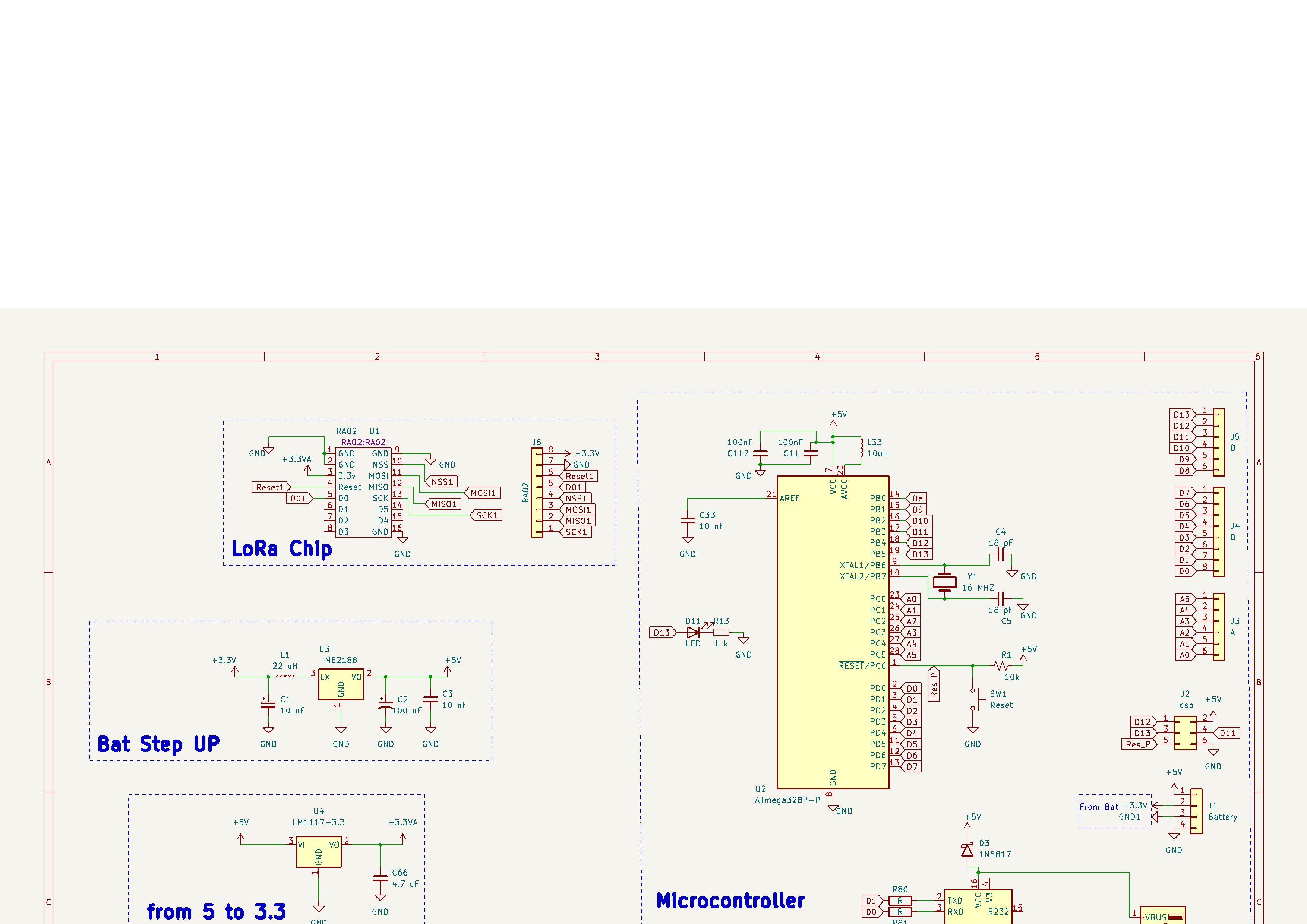
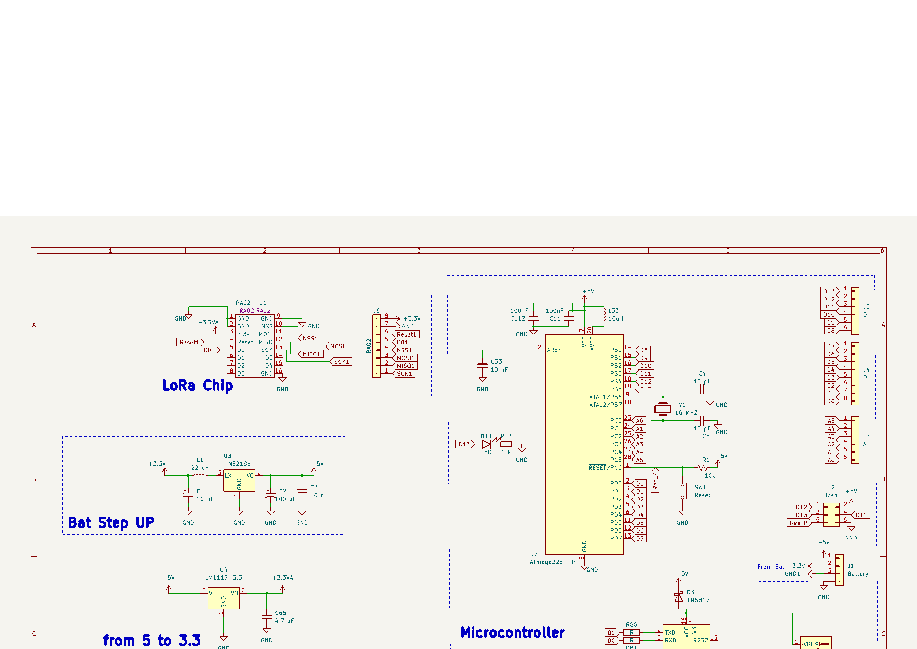
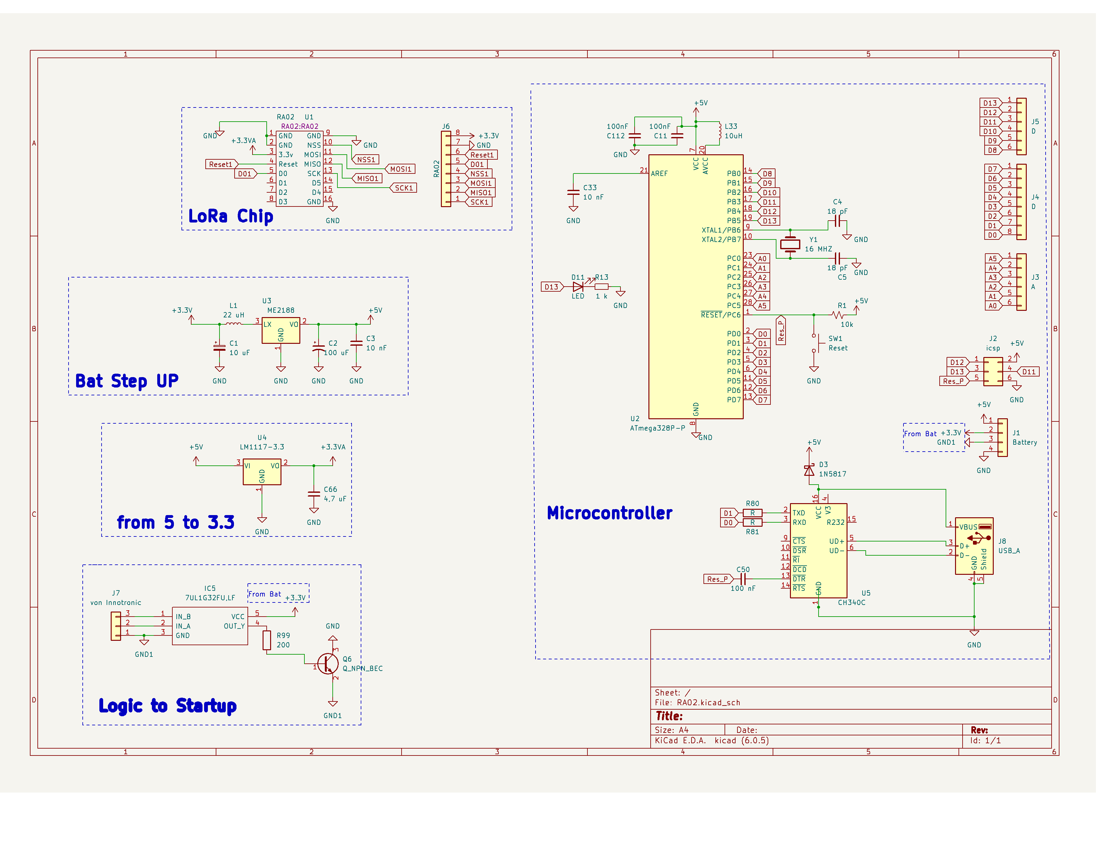
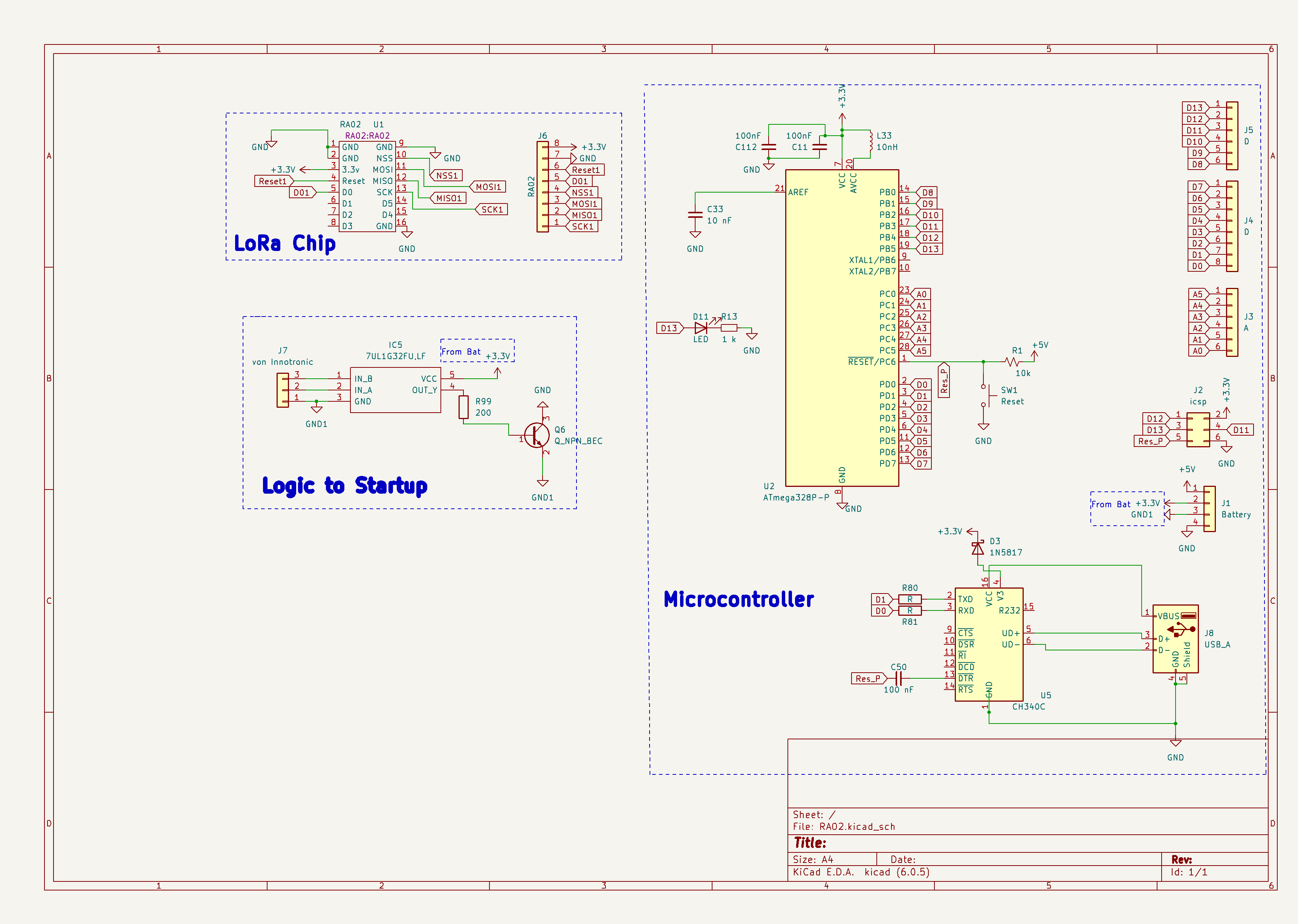
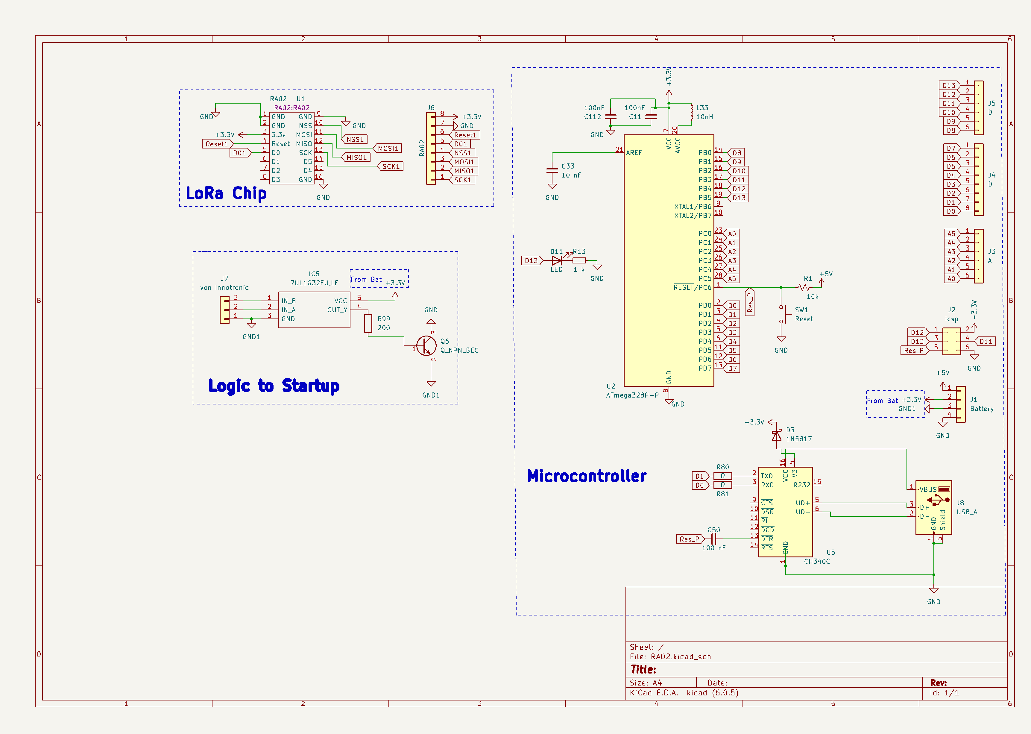
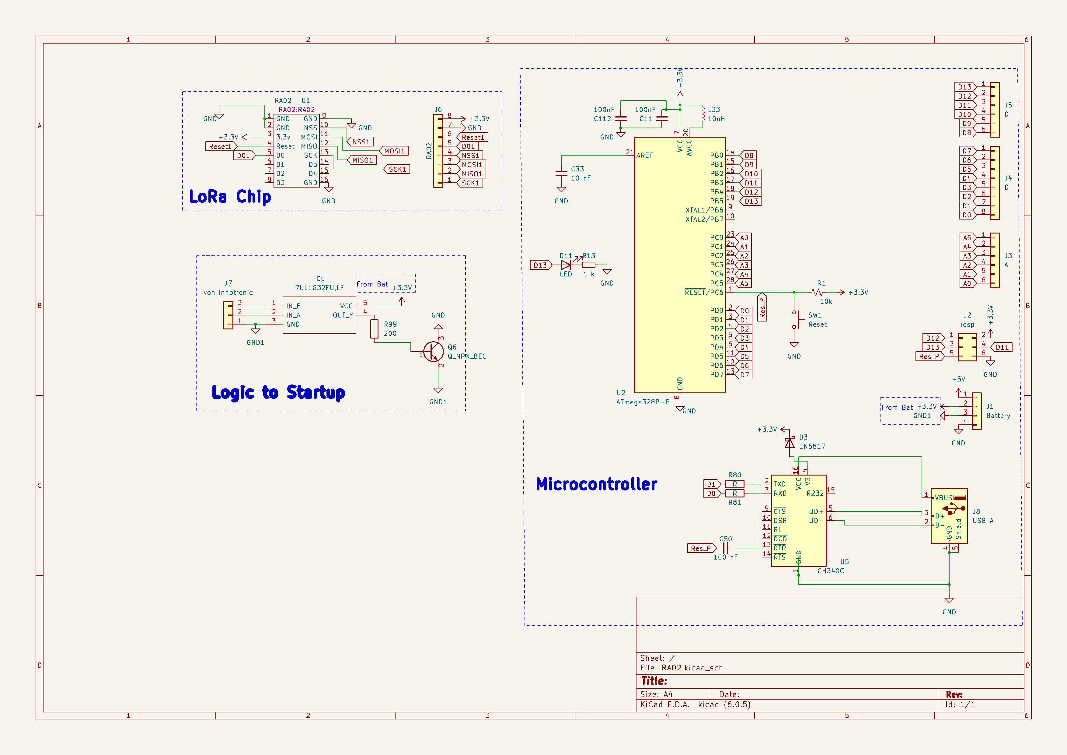
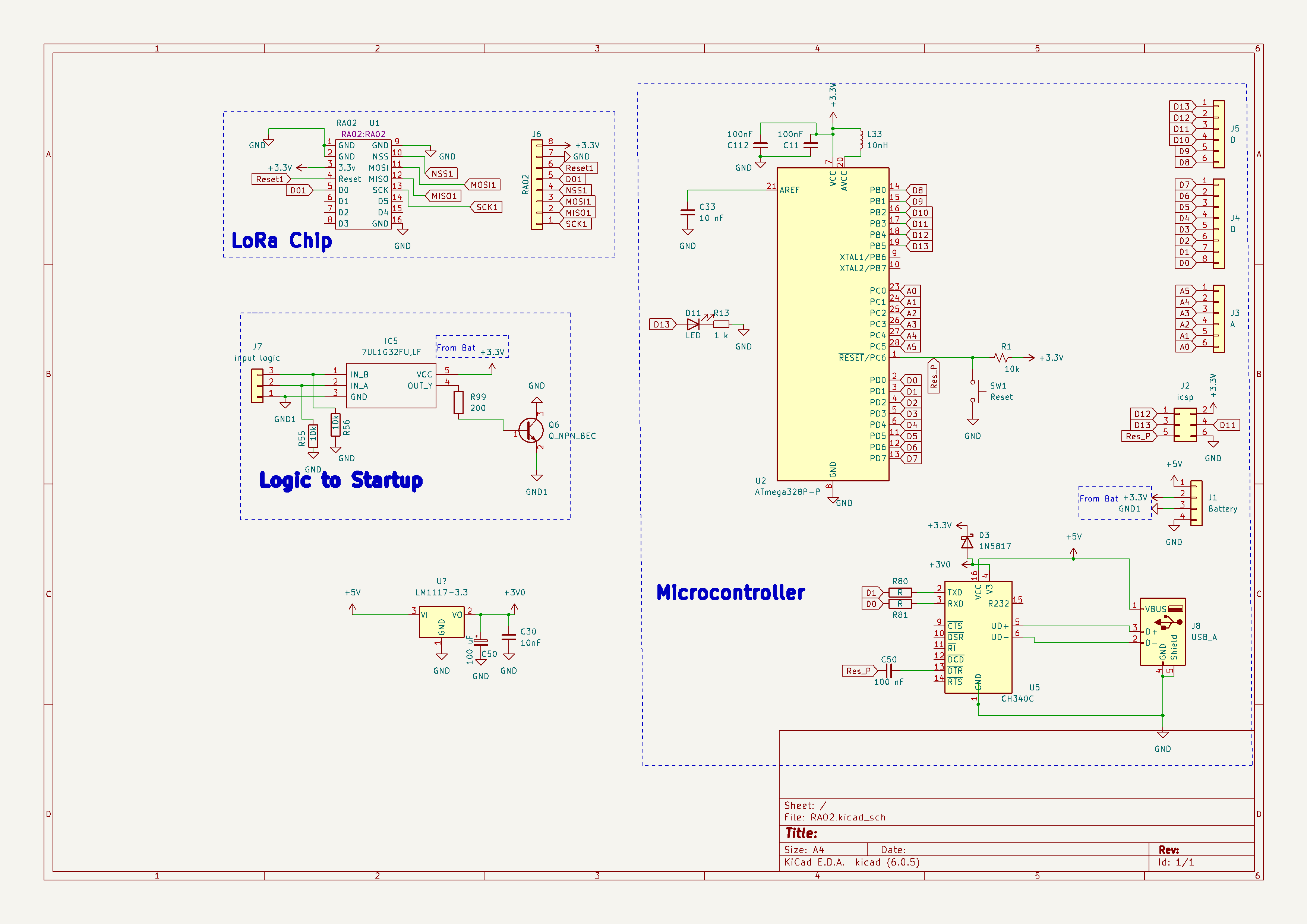
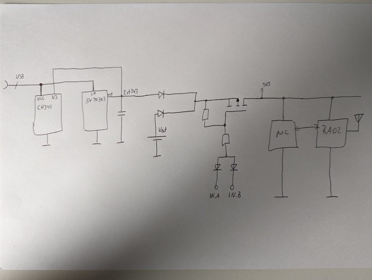
can someone check if my Arduino with LoRa Circuit is correct please ? :)

I want to design PCB , wich start just when a one of two Signals  from
J7 come ,
i use OR-Gate with MMBT5551 BJT to connect the GND1 from battery to GND
in my circuit , and then i will send signal with LoRa chip .

Is my design correct ? will my Schematic working well ?

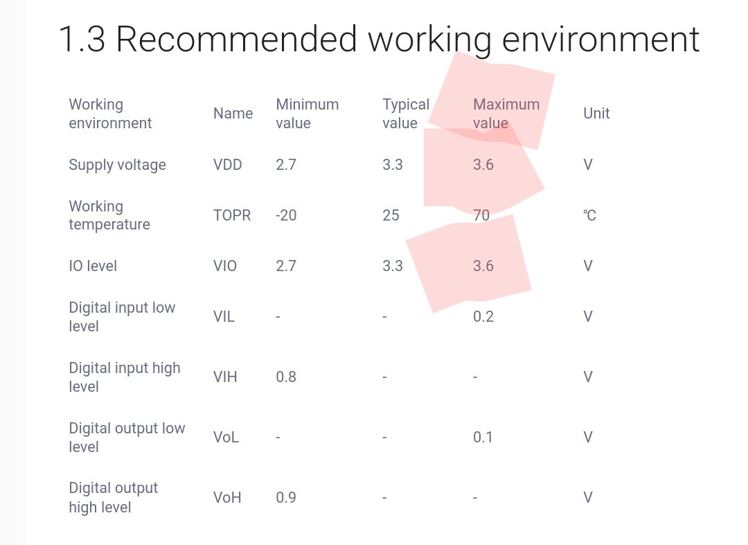
Lora need 100 mA max, uC need about 200 mA max
https://datasheet.lcsc.com/lcsc/1810190020_Changjiang-Electronics-Tech--CJ-MMBT5551_C2145.pdf
Attached files:
-
 Untitled.png
(54 KB)
Untitled.png
(54 KB)
-
 Untitled.png
(54 KB)
Untitled.png
(54 KB)