EmbDev.net

Forum: FPGA, VHDL & Verilog johnson counter


von VhdlTest V. (Company: electronic srl) (vhdluser)


Attached files:

Rate this post
useful
not useful
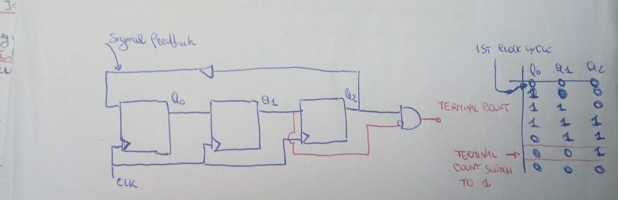
someone can help me with this vhdl code for johnson counter. here is my 
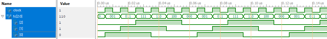
implementation, I'm note sure about that. The correct image is the 
second one.


I have written this code in a first vhdl file, This is the Flip flop 
declaration, I will use it  as a component later :
1
entity register_Johnson_entity is
2
port (D : in std_logic_vector (2 downto 0); clock : in std_logic; reset: in std_logic; q: out std_logic_vector(2 downto 0));
3
end register_Johnson;
4
5
architecture reg_johnson of register_Johnson_entity is
6
7
 flip_flop_async : process( clock, reset)
8
 begin
9
 if reset = '1' then 
10
 q <= (others => "000")
11
 else 
12
 q<= D;
13
 end if;
14
 end process;
15
 
16
 end architecture;

this is the other file that containt the main code, and where I use the 
component flip flop async:
1
use ieee.std_logic_1164.all;
2
3
entity counter_johnson is
4
port (clock: in std_logic; tc: std_logic_vector(2 downto 0);
5
end entity;
6
7
architecture john of counter_johnson is
8
 
9
 signal feedback : std_logic_vector(2 downto 0);
10
 signal q : std_logic_vector (2 downto 0);
11
 
12
 
13
 component register_Johnson_entity is
14
 
15
  port (D : in std_logic_vector (2 downto 0); clock : in std_logic; reset: in std_logic; q: out std_logic_vector(2 downto 0));
16
end register_Johnson;
17
end component;
18
19
-- registers update
20
q(1)<=q(0);
21
q(2)<=q(1);
22
q(2)<= not q(0);
23
24
25
-- the counter is cleared when tc =1
26
reset_jonshon : process(q(2),q(1))
27
 tc<=  q(2) and not q(1);
28
 if tc == '1' then
29
 -- reset operation
30
 q(1)=(2)=q(0)= '0';
31
 else tc == '0';
32
 end process;
33
 
34
-- port map operation
35
36
port map (not feedback => D ;q(0) => D; q(1) => d );

: Edited by User
von Lothar M. (Company: Titel) (lkmiller) (Moderator)


Rate this post
useful
not useful
VhdlTest V. wrote:
> This is the Flip flop declaration
Uhmmm...
This is a kind of some "dual-edge-flipflop". But only in simulation. In 
real life it is a latch. And only two kind of people are using latches: 
first those, who know them and their behavior very well. And second 
those who don't.

You belong to the second ones.

A hint: only simulation shows some kind of interest in the sensitivity 
list. The synthesizer don't. It only tells you, that the simulation 
doesn't math the synthesis result.
So look at your code as if there is no sensitivity list.

Having got that right look how others describe a flipflop in VHDL. A 
hint here: it has something to do with 'event or rising_edge() or 
falling_edge(). The two functions are built on the' event.

von Lothar M. (Company: Titel) (lkmiller) (Moderator)


Attached files:

Rate this post
useful
not useful
VhdlTest V. wrote:
1
-- the counter is cleared when tc =1
2
reset_jonshon : process(q(2),q(1)) // tc is missing here, will result in weird behaviour
3
 tc<=  q(2) and not q(1); // assigning a bit to a vector will not work
4
 if tc == '1' then   // comparisons look much different, we do not 'C'
5
 -- reset operation
6
 q(1)=(2)=q(0)= '0'; // assignments do look much different
7
 else tc == '0';     // assignments do look much different
8
 end process;
Such nasty syntax errors you have throughout the whole code starting at 
the very first line! Just hand your scribblescrabble over to the syntax 
check to get rid of 90% of the errors. And then post it to anyone 
around the world.

> -- reset operation
>  q(1)=(2)=q(0)= '0';
What means the lonely (2) here? Why do you expect such a kind of "queued 
up assignement" is working in VHDL? And why not simply writing q <= 
"000"?

Keep your eyes on a clean and correct sensitivity list or use VHDL-2008 
and the keyword "all" instead of listing single signals.

And at all: i don't see no need for a "reset" in your picture...

My VHDL code for the pictures above would look like this:
1
LIBRARY ieee;
2
USE ieee.std_logic_1164.ALL;
3
4
entity counter is
5
  port (clock: IN  std_logic;
6
        tc:    OUT std_logic_vector(2 downto 0));
7
end counter;
8
9
architecture john of counter is
10
  signal c : std_logic_vector(2 downto 0) := "000";
11
begin  
12
  process begin
13
    wait until rising_edge (clock);
14
    if (c /= "100") then  c <= c(1) & c(0) & not c(2);    
15
    else                  c <= "000";
16
    end if;
17
  end process;
18
  tc <= c;
19
end john;
Or a little bit shorter:
1
LIBRARY ieee;
2
USE ieee.std_logic_1164.ALL;
3
4
entity counter is
5
  port (clock: IN  std_logic;
6
        tc:    OUT std_logic_vector(2 downto 0));
7
end counter;
8
9
architecture john of counter is
10
  signal c : std_logic_vector(2 downto 0) := "000";
11
begin  
12
  c <= c(1) & c(0) & not c(2) when rising_edge(clock);
13
  tc <= c;
14
end john;
And both of them result in the attached waveform.

: Edited by Moderator
Please log in before posting. Registration is free and takes only a minute.
Existing account
Do you have a Google/GoogleMail account? No registration required!
Log in with Google account
No account? Register here.