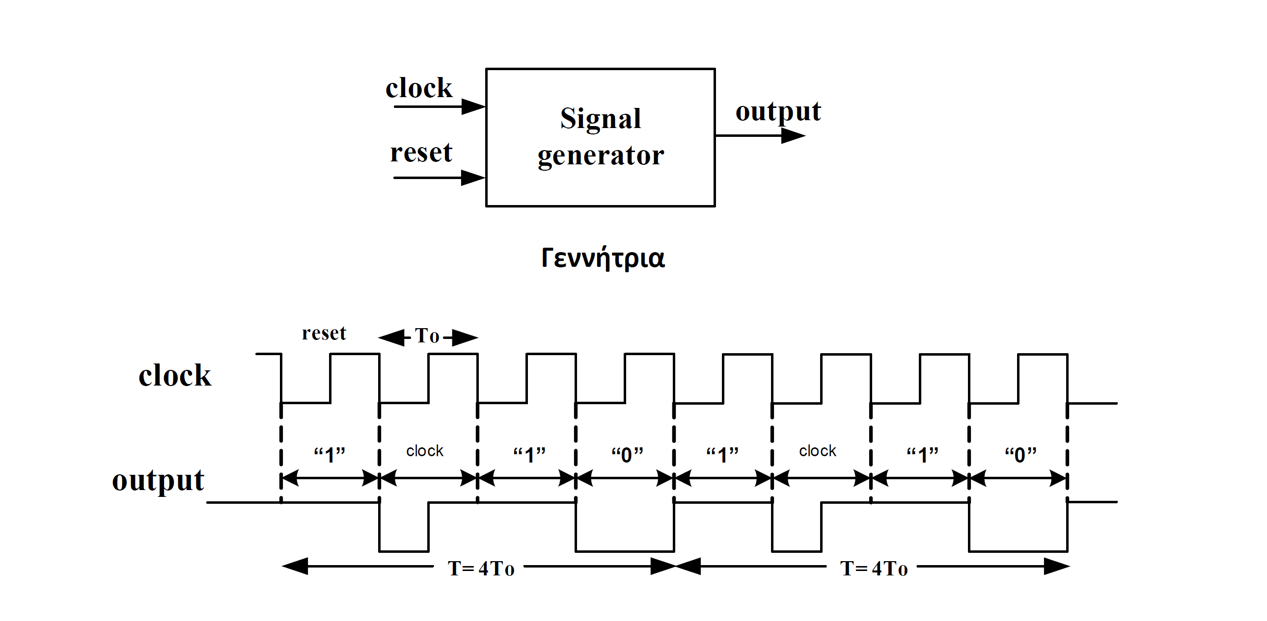
I have to generate the vhdl code for the signal generator attached to
the icon file. What I cant manage to implement is this. How to generate
the clock values to output. To be more specifice, I want for half period
output 0 and the other half 1. My implementation, as you can see on the
code below is output <= clock but this obviously does not work.

My testbench and my vhdl code are these:

testbench

library ieee;
use ieee.std_logic_1164.all;

entity signal_generator_tb is
end entity;

architecture signal_generator_tb_arch of signal_generator_tb is
  signal clock_tb, reset_tb: std_logic;
  signal output_tb: std_logic;

  component signal_generator
    port(clock, reset: in std_logic;
       output: out std_logic);
  end component;

  begin
    dut : signal_generator port map(clock_tb, reset_tb, output_tb);

    stim_reset : process
      begin
        reset_tb <= '0'; wait for 10 ns;
        reset_tb <= '1'; wait;
    end process;

    stim_clock : process
      begin
        clock_tb <= '1'; wait for 10 ns;
        clock_tb <= '0'; wait for 10 ns;
      end process;

end architecture;

and my vhdl code is that:

library ieee;
use ieee.std_logic_1164.all;

entity signal_generator is
  port (clock, reset: in std_logic;
       output: out std_logic);
end entity;

architecture signal_generator_arch of signal_generator is
  type state_type is (s0, s1, s2, s3); --This is the states of the
finite state machine and we can create signlas with this type
  signal current_state, next_state: state_type; --We can only assign
w_open and w_closed because there are type of state_type

  begin
    STATE_MEMORY : process(clock, reset)
      begin
        if(reset = '0') then
          current_state <= s0;
        elsif(falling_edge(clock)) then
          current_state <= next_state;
        end if;
      end process;

    NEXT_STATE_LOGIC : process(current_state)
      begin
        case(current_state) is
          when s0 => next_state <= s1;
          when s1 => next_state <= s2;
          when s2 => next_state <= s3;
          when s3 => next_state <= s0;
          when others => next_state <= s0;
        end case;
      end process;

    OUTPUT_LOGIC : process(current_state)
      begin
        case(current_state) is
          when s0 => output <= '1';
          when s1 => if(rising_edge(clock)) then
                  output <= '1';
                else
                  output <= '0';
                end if;
          when s2 => output <= '1';
          when s3 => output <= '0';
          when others => output <= '0';
        end case;
      end process;
end architecture;
Attached files:
Thanks but what if I want to implement this as a finite state machine?
Before writing code, think more generally about the problem. The output
signal obviously changes on both clock edges. So you will need two state
machines, one rising clock edge triggered, the other falling edge
triggered. Keep both FSMs strictly seperated, otherwise you will get
something that runs perhaps somehow in a simulation but never in
hardware. Finally, use a combinatorial logic that generates the output
waveform from the states of both FSMs.
Other possibilities
- double the clock frequency
- use DDR output circuit (ODDR)
One of these would be my favourite way to avoid combinatorial circuits.
Please log in before posting. Registration is free and takes only a minute.
Existing account
Do you have a Google/GoogleMail account? No registration required!
Log in with Google account
Log in with Google account
No account? Register here.