EmbDev.net

Forum: µC & Digital Electronics Two ESP32 together for programming


von Danny (Guest)


Attached files:

Rate this post
useful
not useful
Hello everyone,

I'm quite new to microcontroller and prgramming. I already flashed some 
firmwares (with ESP32 development board) and programmed something for 
myself. For my current project (a LED lamp) I need a smaller controller, 
because of the limited size. So I decided to go with an ESP32 chip 
without the development board. I soldered the needed cables directly to 
the chip  and connected this to  an other ESP32 (development board). I 
just want to flash a bootloader and a firmware (WLED) I checked the 
soldering and the wiring multiple times, but no success with the 
connection. I don't see my mistake and hope somebody can help me out 
here.

For programming I exceute
1
esptool.py write_flash 0x0 bootloader.bin
 hold the boot- (without resistor) and press the reset button (with 10K 
resistor), but I always get no connection.

So my quesstions are:
Is my wiring correct?
Is there an easier way for just programming the controller?
Is my command correct or do I have to use some special parameters 
(couldn't find anything in the manpage)?


Thanks in advance,
Danny


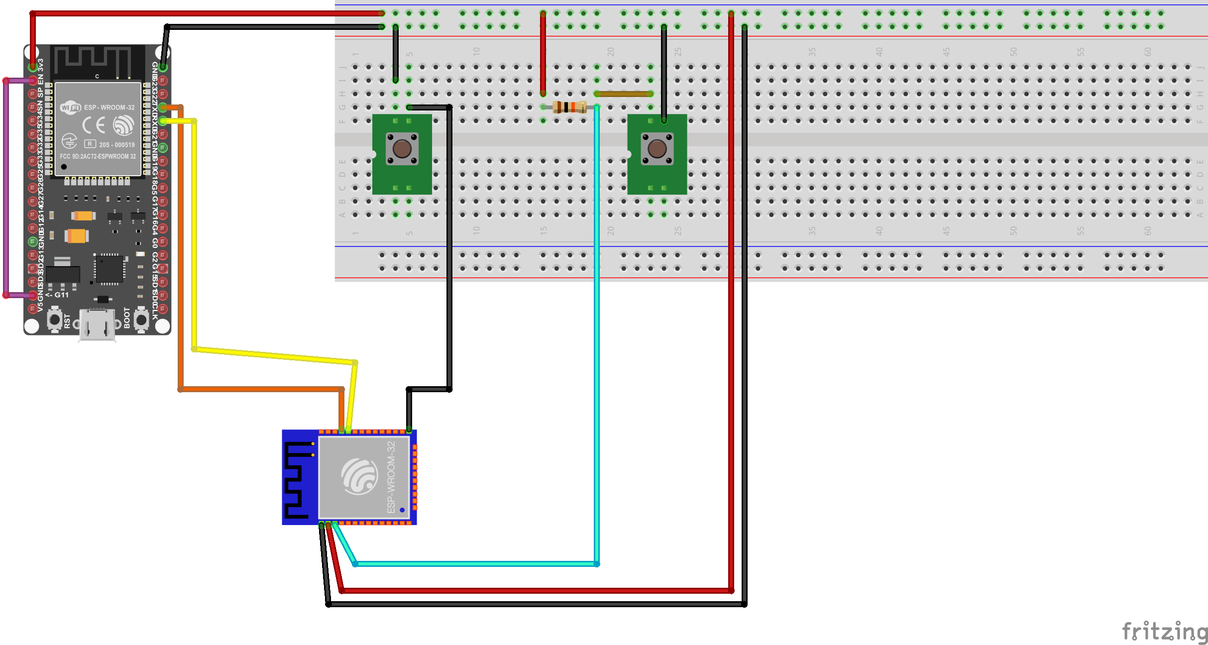
PS: I've attached a schema of my wiring.

The chip wiring is:

TOP:
TX -> TX of dev board;
RX -> RX o dev board;
GND -> reset button

BOTTOM:

GND  -> GND;
3.3V - > 3.3V;
EN -> resistor

von stefanus (Guest)


Rate this post
useful
not useful
Some more I/O pins need a specific logic Level allow a proper startup.

von Danny (Guest)


Rate this post
useful
not useful
stefanus wrote:
> Some more I/O pins need a specific logic Level allow a proper
> startup.

Sorry, I don't understand what you are trying to say. Do I need more 
wires, resistors to the chip? If so, which ones?

von Andree S. (amshh)


Rate this post
useful
not useful
stefanus wrote:
> Some more I/O pins need a specific logic Level allow a proper startup.

No. This is wrong. Or not the whole truth. The mentioned I/O Pins are 
satified if leaved open.

I've built a programming adapter for the ESP32 with exactly the signals 
Danny provided.

Beitrag "Re: Zeigt her eure Kunstwerke (2020-2021)"

And this works well.

Danny's problem must be different.
Danny >> Are you sure to start the bootloader before downloading?
Means: EN LOW >> GPIO-0 LOW  >> EN HIGH >> GPIO-0 HIGH ???

Regards
Andree

: Edited by User
von Andree S. (amshh)


Rate this post
useful
not useful
Sorry, cannot insert the link correctly ....

Beitrag "Re: Zeigt her eure Kunstwerke (2020-2021)"

It's from 04.12.2021 15:33

von Danny C. (danny89)


Rate this post
useful
not useful
Andree S. wrote:
>
> Danny's problem must be different.
> Danny >> Are you sure to start the bootloader before downloading?
> Means: EN LOW >> GPIO-0 LOW  >> EN HIGH >> GPIO-0 HIGH ???
>
> Regards
> Andree

Hello Andree,

thank you for your reply.

I'm not quite sure, I press both buttons and after 1s i release the 
reset one. Can you please check my schema at the buttons, if this is 
possible with my soldering? I've changed the schema of this link:

https://www.14core.com/wiring-and-flashing-programming-esp-32-esp32s-with-usb-ttl-uart/

a little bit to my needs and I_m not quite sure if this correct.

Thank you in advance,
Danny

von Andree S. (amshh)


Rate this post
useful
not useful
Refering your picture at the beginning:

You shortcut both TX/TX and RX/RX signals of the first and the second 
ESP32. Bad idea! For RX/RX this maybe ok.... but TX are outputs and both 
output drivers then work against each other. And even worse: The 
download stream will send its request for downloading to both ESP32 
simultaneously. And only one of them is in bootloader mode ...
I would consider that what you like to do is impossible this way. My 
advice: Throw away the ESP32 Development module, take a CP2102 USB/UART 
Bridge connected to your PC with the IDE and on the other side to the 
ESP's Rx/Tx (correctly!) and power your ESP32 chip with a sufficiant 
power supply.

von Danny C. (danny89)


Rate this post
useful
not useful
Sorry for the late reply and thank you for your answer. Programming with 
the second ESP32 should normally work, according to this video:
https://www.youtube.com/watch?v=ndEeFQ5mi_g (at 4:58 min)
I tried it this way, because I have no UART-programmer. I will try a 
little bit, but I thin it will be better to buy such a little 
programmer.
Another question, because you seem very familiar with this little chips 
and without boards.

After successfully flashing the firmware is it enough to connect power 
and ground or do I need something else (capacitor, resistor, ...) to 
boot up and use it?

Thanks for your help.

Please log in before posting. Registration is free and takes only a minute.
Existing account
Do you have a Google/GoogleMail account? No registration required!
Log in with Google account
No account? Register here.