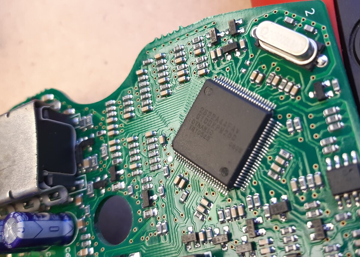
Hello guys

I'm in front of this µcontroller named : 2622A44FAV.
No information available on Google.

This µcontroller is seated in a invacare wheelchair ECU (ref DK-PMB21).
The ECU is build by the Dynamic compagny located in New zeland. It's
also the brand I found on the µcontroller.

Do you know more from this part ?
Should I consider it's a part build exclusively for Dynamic ?
Or (my assumption) it's a regular µcontroller with only a dynamic
labelling ?
In this case what method should I use to find the real hidden part
number ?

Thks for your support.
vincent
Attached files:
-

20211109_113332.jpg
230 KB
What is the marking on the SO8 component on the right ?

What dies your chip do, control 2 BLDC motors with sensors ?

May it be sn FPGA with serial EEPROM and the black epoxy dot on the left
is the uC ?

There is no way to repair. If it is a programmed uC, you do not have the
program. And probably it is not defective.
MaWin schrieb:
> and the black epoxy dot on the left is the uC ?

That looks like a round hole in the PCB to me.
Vincent H. wrote:
> Or (my assumption) it's a regular µcontroller with only a dynamic
> labelling ?
> In this case what method should I use to find the real hidden part
> number ?
Try acetone. Sometimes it unveils hidden information...
Attached files:
-

20211108_141328.jpg
240 KB
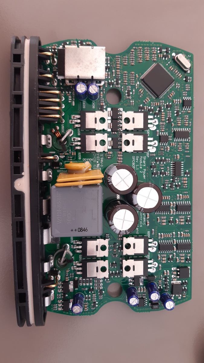
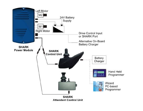
Thks for your replies


The part on the right is a 16K EEPROM (24LC16B)
I have absolutly no clue...what this chip could be.

This ECU manages the jostick, the motors and the back recline motor, the
lights and the battery charging. That's a lot ...

I start to retro-engineer the ECU to take over the H-bridge (at least)
and maybe some other functions for another purpose.
This can be a cheap way to handle the 70 amps motors.

H-bridge command circuitry is quite easy to find with the 4x2 MOSFET + 4
H-bridge drivers (IR21844).

Here the full view of the (nice and well build) PCB.
Vincent
Vincent H. wrote:
> In this case what method should I use to find the real hidden part
> number ?

The simple but stony path is to reconstruct the schematic (at first the
GND and VCC and Clock and reset connections) and search in the internet
for a matching chip.

And when you found a pincompatible chip, you are not at the end of your
journey, but rather just one step away from the starting line. To make
your own firmware, you need a lot more of effort. And do not believe,
that a firmware on a chip labeled on customers request is readable.
Particularly if the chip has a damage.

Good luck.

W.S.
W.S. wrote:
> Vincent H. wrote:
>> In this case what method should I use to find the real hidden part
>> number ?
>
> The simple but stony path is to reconstruct the schematic (at first the
> GND and VCC and Clock and reset connections) and search in the internet
> for a matching chip.
>
> And when you found a pincompatible chip, you are not at the end of your
> journey, but rather just one step away from the starting line. To make
> your own firmware, you need a lot more of effort. And do not believe,
> that a firmware on a chip labeled on customers request is readable.
> Particularly if the chip has a damage.
>
> Good luck.
>
> W.S.

Yeap

That's why a plan to graft a ESP32 on top of that and hook up all
connection a need.

Thks
choucroutemelba wrote:
> The part on the right is a 16K EEPROM (24LC16B)

This EEPROM is too small to hold the complete firmware for a FPGA, so it
probably only stores user parameters.

choucroutemelba wrote:
> This can be a cheap way to handle the 70 amps motors.

Not in this circuit. This is way to tiny to handle 70Amps. You should
provide at least 5 times the current the motors draw to be on the safe
side - e.g. 3 IRFB3205 in parallel for each MOSFet.
Attached files:
-

schematic.JPG
34 KB -

power.JPG
32 KB -

Electrical_specs.JPG
77 KB

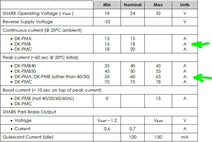
matzetronics wrote:
> This EEPROM is too small to hold the complete firmware for a FPGA, so it
> probably only stores user parameters.

Yes this is also my point of view

matzetronics wrote:
> Not in this circuit. This is way to tiny to handle 70Amps. You should
> provide at least 5 times the current the motors draw to be on the safe
> side - e.g. 3 IRFB3205 in parallel for each MOSFet.

I wrote it unclear. The motors are given for 70 amps but it's the peak
current.
The ECU can provide 18A nominal, 60A during < 60sec and additional 15A <
10sec.
I'll look closely to the MOSFET but ECU & motors are build in so they
should works properly together.

Attached some pictures
The Package and this Marking looks like an Renesas/Hitachi H8 derivat.
The H8S/2258 seems to fit with the Quartz and some Vcc pins but not with
all pins.
It is an H8S/2622. The H8S/2622 is described in the Manual of the
H8S/2623. The main differences are:

           Mask ROM    RAM
H8S/2622   128k        8k
H8S/2623   256k        12k

https://www.farnell.com/datasheets/101892.pdf
Please log in before posting. Registration is free and takes only a minute.
Existing account
Do you have a Google/GoogleMail account? No registration required!
Log in with Google account
Log in with Google account
No account? Register here.