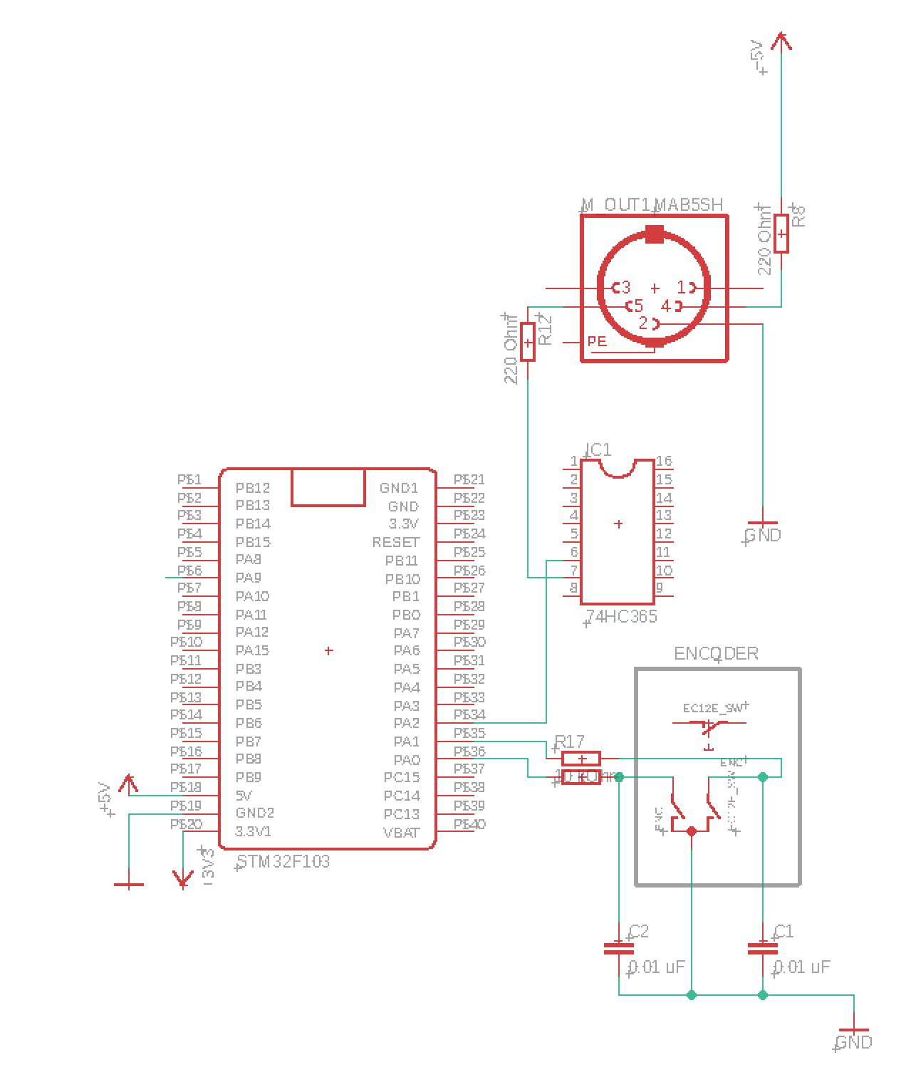
Hey,

i am currently working on a MIDI related project utilizing a STM32F103
and a Hex Buffer (74HC365). I have the following problem: reading the
encoder works fine (handled via interrupts) until i connect a midi cable
to the midi out port, then the readings of the encoder get sloppy. I
think it might be some interference problem, since everything works
fine, when i attach a serial adapter instead of a midi cable to the
output.

I attached a simplified schematic of my curcuit.

Do you have any idea what could cause the problem and how i can protect
my circuit?
Attached files:
The internal Pull-Up resistors habe about 50kΩ, so they are very weak.
The lines can easily receive radio signals.

You need stronger Pull-Up resistors, for example 2,2kΩ. Also your
capacitors are on the wrong side. The encoder contacts will shorten the
capacitors, which leads to short pulses of very high current.

Better:
1 | 2.2kΩ |
2 | |
3 | 3,3V o--[===]--+ 100Ω |
4 | | |
5 | µC o-----------+---[===]---o Encoder contact |
6 | | |
7 | === |
8 | | |
9 | GND o----------+-----------o |
i just figured it i make the ground connection closer to the power
supply the problems disappears. any idea what could be happening there?
Search for en explanation of "ground loop" and why GND connections shall
form a star to work properly. The web is full of related documentation.
Hey Stefanus!

Thanks a lot. your circuit seems to work much better - meaning without
any problems! i placed some pullup resistors, and you are right: the
capacitors should be placed behing the 100 Ohm resistors.
Lutz wrote:
> any idea what could be happening there?
The usual EMC effects.

But because no one knows anything about the real hardware it results in
guessing: lousy GND layout, missing or useless decoupling caps,...
im still working on a breadboard to test out all the components. so
there is not really any propper GND layout yet. but it will follow your
advices when i create the pcb layout.
The main related pyhsical effect is:

Every line has an inductance and a capacitance. So every line is more or
less an antenna (more for higher frequencies) which sends and receives
radio signals.

Also the purpose of GND is a unique common potential that all signals
are derived from. If you have a few centimeters of GND wire, it will
have already more than 0 Ohm. As higher the frequency, as higher the
resistance. And resistance together with currency produces a voltage
drop.

So GND is not the same GND everywhere, and that arises lots of different
problems.
> im still working on a breadboard

Breadboard make it even worse because the usually have contacts and
cables made from iron which has a significantly higher resistance than
copper.

Consider to solder the power supply wires and plug only the signal wires
which are less critical.
Please log in before posting. Registration is free and takes only a minute.
Existing account
Do you have a Google/GoogleMail account? No registration required!
Log in with Google account
Log in with Google account
No account? Register here.