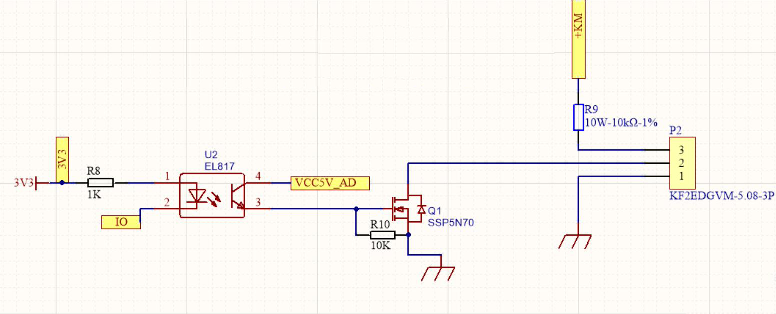
The single-chip microcomputer drives the IO port, and the reaction time
of the top and bottom edges of the optocoupler 3 pins is basically
within 1ms, but the top and bottom edges of the mos tube switching
waveform are basically about 40ms. The drain in the figure has been
connected to the +KM and 10K resistors through the wiring terminals. The
switching response time Why is it so long?
Attached files:
-

QQ__20211026163351.png
390 KB
This MosFet is absolute unsuitable for a gate voltage of 5V.
Sunny Y. schrieb:
> Why is it so long?

Please keep im mind, that the gate of the FET is good insulated, so it
does not consume much current while it is held in a constant state, but
on the other hand it has a remarkable capacity to source and do drain.
Therefore to drive the gate from one voltage to another, it needs a
rather big amount of current to do it fast. When your driving circuit
cannot deliver this current, your switching speed will be slow. So the
best is to use a dedicated gate driver. Such a chip is capable to
deliver a suitable current to the gate to speed up the switching. For
example: the Tc4420 can deliver up to more than 1 ampere when driving
L->H and up to 6 ampere when driving H->L (both just only for a short
time).

W.S.
To switch the MOSFET you need to charge/discharge its gate. For
simplicity, think of it as a capacitor.
Use the parameter "Total gate charge" in the MOSFET datasheet, which is
56nC for 10V. That is a lot, meaning your MOFET needs a lot of current
to switch fast.

Your rising edge is limited by the current driving capability of your
photo-coupler. There is a ratio "CTR" (=current transfer ratio), which
limits the photo-transistor current of your photo-coupler, depending on
how much current the photo-coupler LED gets.
Your photo-coupler has a CTR of 50 to 600%.

your falling edge is limited by the time constant of Cgate and the 10k
resistor (which is in the µs-range).

As others mentioned bevore, your MOSFET is not usable for 5V gate
voltage.
Don not use the gate threshold as indication for your gate drive
voltage. Instead, look for the voltage the Rdson is rated. In this case,
this would be 10V.

For 5V, your RDSon will be terrible. Switching on will be very slow,
since the photocoupler transistor also has an saturation voltage you
will not get 5V anyway. Which might be the problem for your rising edge
in the ms-range.

to sum it up:
With this type of MOSFET, you may want to use gate driver of some sort
and a higher gate drive voltage, e.g. 10V.
You may be able to use a logic level Mosfet without gate driver,
depending on your application.
Please log in before posting. Registration is free and takes only a minute.
Existing account
Do you have a Google/GoogleMail account? No registration required!
Log in with Google account
Log in with Google account
No account? Register here.