EmbDev.net

Forum: FPGA, VHDL & Verilog Synchronous two PWM signals generator


von Stas I. (stasik_30)


Attached files:

Rate this post
useful
not useful
Hi to all,

I try to generate two synchronous PWM signals however I missing 
something. I'll be grateful if you could assist me.

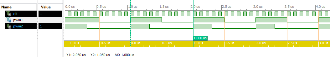
1. Two signals should start at the same time.

2. When PWM_1 is rising edge the PWM_2 should be start either.

3. PWM_1 is 1us period , 0.5 uS high ('1') and 0.5 uS low ('0'). 50% 
Duty cycle.

4. PWM_2 is 1uS period , 0.3uS high ('1') and 0.7 us low ('0'). 30% Duty 
cycle.

Code and simulation attached .
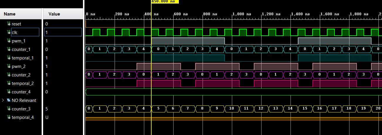
Simulation :
Attached image of simulation Sim.PNG


CODE :
1
LIBRARY IEEE;
2
USE IEEE.STD_LOGIC_1164.ALL;
3
4
ENTITY clk1 IS
5
PORT (
6
clk : IN STD_LOGIC;
7
reset : IN STD_LOGIC;
8
clk_out : OUT STD_LOGIC;
9
pwm_1 : OUT STD_LOGIC;
10
pwm_2 : OUT STD_LOGIC
11
);
12
END clk1;
13
14
ARCHITECTURE Behavioral OF clk1 IS
15
SIGNAL temporal_1 : STD_LOGIC;
16
SIGNAL temporal_2 : STD_LOGIC;
17
SIGNAL temporal_4 : STD_LOGIC;
18
SIGNAL counter_1 : INTEGER RANGE 0 TO 4 := 0;--780 original
19
SIGNAL counter_2 : INTEGER RANGE 0 TO 4 := 0;--780 original
20
SIGNAL counter_3 : INTEGER RANGE 0 TO 4 := 0;--780 original
21
SIGNAL counter_4 : INTEGER RANGE 0 TO 4 := 0;--780 original
22
BEGIN
23
freq_divider_1 : PROCESS (reset, clk)
24
BEGIN
25
26
IF rising_edge(clk) THEN
27
counter_3 <=counter_3+1;
28
--counter_4 <=counter_3+1;
29
END IF;
30
31
IF (reset = '1') THEN
32
temporal_1 <= '0';
33
counter_1 <= 0;
34
ELSIF rising_edge(clk) THEN
35
36
IF (counter_1 = 4) THEN
37
38
temporal_1 <= NOT(temporal_1);
39
40
counter_1 <= 0;
41
ELSE
42
counter_1 <= counter_1 + 1;
43
END IF;
44
45
END IF;
46
47
48
IF (reset = '1') THEN
49
temporal_2 <= '0';
50
counter_2 <= 0;
51
ELSIF rising_edge(clk) THEN
52
53
IF (counter_2 = 3) THEN
54
55
temporal_2 <= NOT(temporal_2);
56
counter_2 <= 0;
57
ELSE
58
counter_2 <= counter_2 + 1;
59
IF counter_2 = 2 THEN
60
temporal_2 <= '0';
61
ELSE
62
temporal_2 <=temporal_2;
63
END IF;
64
END IF;
65
66
END IF;
67
68
END PROCESS;
69
70
clk_out <= temporal_1;
71
pwm_1 <= temporal_1;
72
pwm_2 <= temporal_2;
73
74
END Behavioral;


Thanks.

Stas.

: Edited by Moderator
von Lothar M. (Company: Titel) (lkmiller) (Moderator)


Rate this post
useful
not useful
The forum sw has some problems with correct rendering since the last 
update...

But to cut down your code it looks like that:
1
freq_divider_1 : PROCESS (reset, clk)
2
BEGIN
3
4
IF rising_edge(clk) THEN
5
:
6
END IF;
7
8
9
IF (reset = '1') THEN
10
:
11
ELSIF rising_edge(clk) THEN
12
:
13
END IF;
14
15
16
IF (reset = '1') THEN
17
:
18
ELSIF rising_edge(clk) THEN
19
:
20
END IF;
21
22
END PROCESS;
Where did you find that fairless amazing coding style with several 
"subprocesses" in one process?

Are you sure, that your synthesizer is able to generate hardware out of 
this?

> however I missing something.
I would implement 1 counter steadily counting from 0 to 9. One step each 
100ns. Then I would set both of the PWM outputs high with counter = 0, 
and I would reset one PWM output with counter = 4 and the second PWM 
output with counter = 6. Sounds kind of easy...

von Stas I. (stasik_30)


Rate this post
useful
not useful
Thank you Lothar.
It has been synthesized. I tried what you had offered and the  PWM 2 
doesn't starts synchronous with PWM 1, it synchronous for the first time 
only.

I changed my code at all. Similar to state machine.
Thank you a lot.
My regards,
Stas.

von Lothar M. (Company: Titel) (lkmiller) (Moderator)


Attached files:

Rate this post
useful
not useful
Stas I. wrote:
> I tried what you had offered and the  PWM 2 doesn't starts synchronous
> with PWM 1, it synchronous for the first time only.
With only 1 counter for both of those PWM outputs they never ever can 
get out of synchronicity:
1
library IEEE;
2
use IEEE.STD_LOGIC_1164.ALL;
3
4
use IEEE.NUMERIC_STD.ALL;
5
6
entity doublepwm is
7
    Port ( clk  : in  STD_LOGIC;
8
           pwm1 : out  STD_LOGIC := '1';
9
           pwm2 : out  STD_LOGIC := '1');
10
end doublepwm;
11
12
architecture Behavioral of doublepwm is
13
signal cnt : integer range 0 to 9 := 0;
14
constant pwmvalue_1 : integer := 5;
15
constant pwmvalue_2 : integer := 3;
16
begin
17
   process begin
18
      wait until rising_edge(clk);
19
20
      if cnt = 9 then  cnt <= 0;
21
      else             cnt <= cnt + 1;
22
      end if;
23
      
24
      if cnt = 0 then
25
         pwm1 <= '1';
26
         pwm2 <= '1';
27
      end if;
28
      
29
      if cnt = pwmvalue_1 then
30
         pwm1 <= '0';
31
      end if;
32
33
      if cnt = pwmvalue_2 then
34
         pwm2 <= '0';
35
      end if;
36
      
37
   end process;
38
end Behavioral;

Please log in before posting. Registration is free and takes only a minute.
Existing account
Do you have a Google/GoogleMail account? No registration required!
Log in with Google account
No account? Register here.