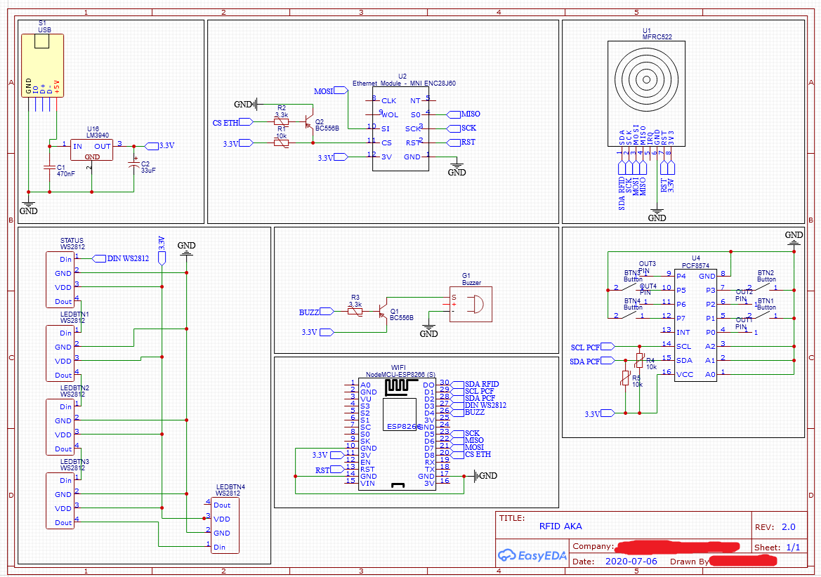
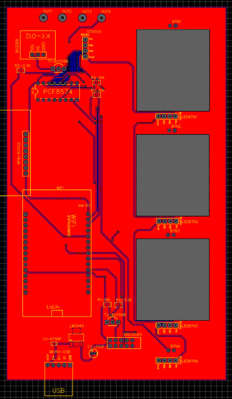
Hello,

I've been working on a project for quite a while now, which involves the
ESP8266 NodeMCU (v1.0), as well as two SPI Modules: ENC28J60, and
RFID-RC522. With that being said, I encountered a problem recently,
which I haven't been able to resolve so far. Working with
micro-controllers and electronics is still a learning experience for me,
so my knowledge here is limited. When I assembled the prototype for my
project on breadboards, everything was working fine in the end. So I
thought I can move on, and design my first PCB (ever).

After doing so, I quickly noticed that something is not working right:
When inspecting the serial output, I found out that only the
Ethernet-module (ENC28J60) has been recognized, whereas the
initialization of the RFID-module (RFID-RC522) didn't work out. My first
guess was, that the RFID-module was broken. After testing only the
module on the breadboard, the initialization of the RFID-module worked
out fine. Also, when only pluging the RFID-module into my PCB, it is
recognized without any problems.

After some research, I found out the problem might stem from the
SPI-lines on my PCB, as they should approximately have the same length
when working with high frequency devices, such as the ESP (
https://resources.pcb.cadence.com/blog/2019-tips-for-optimal-high-speed-spi-layout-routing
). So I designed another PCB, with exactly this condition (+ I also
tried to keep the SPI-routes short). When I soldered my newly designed
PCB, I still got no positive result. The problem stays the same.

Does anyone have an idea, why only one of the SPI-devices is recognized,
during initialization phase? The initialization of all the other devices
works fine. I have attached the schematics of my PCB-design to this
thread. I have also attached a picture of the resulting PCB.

As a side information: I am using the LM3940 voltage regulator. When
measuring the voltage, I get almost exactly 3.3 V (as required by my
modules).

I would really appreciate any comment and help on this.

Please let me know if some information is missing. I will reply as soon
as I can.

With best regards,
Ed
Attached files:
-

RFID-AKA-Schematic-2_0.PNG
130 KB -

20201202_221144.jpg
210 KB
Hi,

i found this pinout for the RC522.

https://lastminuteengineers.com/how-rfid-works-rc522-arduino-tutorial/

Is your SDA_RFID signal, a slave-select signal?

T
Hey T,

thanks for the reply.
yes, the SDA_RFID pin is the D0 pin on the ESP, which is configured as
an output pin. It is passed to the RFID-lib I am using (called MFRC522)
as slave-select.

best regards,
Ed
Ok,

So, firstly, on a breadboard the same schematics work, meaning, you are
sharing the serial bus between the 2 slaves. I guess you are sequencing
serial comms. Which slave is first and which one is second? What serial
clk speed? What spi mode?

Then, realization of the same schematics onto a pcb and it fails when 2
slaves are connected.
What if one slave connected? What if the other only connected?

Would be nice if you could post the routing of your board, to see the
serial bus tracks.

T
Ed S. wrote:
> The problem stays the same.
Now its time for a reasonably fast 4-channel-digital-scope.

Or for any kind of "fast enough" scope to check the waveform quality
(how do the signals look lie at the Pins of the components) and
additionally a logic analyzer for the protocol.
Attached files:

Hello T,

SparkyT wrote:
> Ok,
>
> So, firstly, on a breadboard the same schematics work, meaning, you are
> sharing the serial bus between the 2 slaves. I guess you are sequencing
> serial comms. Which slave is first and which one is second? What serial
> clk speed? What spi mode?
>
In my code, I first initialize the RFID-module. This is also where I get
an error in the serial monitor (this worked on the breadboard before).
After that, the Ethernet-module is initialized (the CS-pin here needs to
be configured in the library header-file itself). For the ESP I
configured a baud-rate of 115200. Regarding your last question I am not
sure what you mean, as I am not initializing the SPI-communication in
detail. In my setup routine I am just calling
1 | SPI.begin() |
. The communication itself is handled by the libraries I am using for
the SPI-modules.

> Then, realization of the same schematics onto a pcb and it fails when 2
> slaves are connected.
> What if one slave connected? What if the other only connected?
>
If I only connect the RFID-module (Without the Ethernet-Module), the
RFID-module is initialized correctly. Connecting the Ethernet-Module
works in both cases.

> Would be nice if you could post the routing of your board, to see the
> serial bus tracks.
>
> T

I attached screenshots (Top- and Bottom Layer) of the routing of my
board to this comment. Unfortunately I haven't labeled the pins on my
board. The very bottom solder-pad for the RFID-module corresponds to the
SDA-pin.

I hope my answer helps!

Best regards,
Ed
Lothar M. wrote:
> Ed S. wrote:
>> The problem stays the same.
> Now its time for a reasonably fast 4-channel-digital-scope.
>
> Or for any kind of "fast enough" scope to check the waveform quality
> (how do the signals look lie at the Pins of the components) and
> additionally a logic analyzer for the protocol.

Hello Lothar,

thanks for your comment. Unfortunately I don't have access to a
4-channel-digital-scope, or a logic analyzer. I only have basic
equipment as working on this project is "just" a hobby.
I will ask around, maybe some friend has access to these devices.

Best regards,
Ed
Did you omid the capacitors at the ICs (100nF)?
Attached files:
-

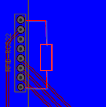
pull-up.png
9.4 KB
Hi,

how about trying a pull-up resistor on SDA_RFID as attached?
try 4k7 and solder on bot layer.
The more i read about the MFRC522 in multiple slaves setup, the more
people have solved issues with pull-ups on the SDA input!

T
SparkyT wrote:
> Hi,
>
> how about trying a pull-up resistor on SDA_RFID as attached?
> try 4k7 and solder on bot layer.
> The more i read about the MFRC522 in multiple slaves setup, the more
> people have solved issues with pull-ups on the SDA input!
>
> T

Hello T,

I had a lot of work the last few days. I will try your suggestion and
report on the outcome, Thanks!

Best regards,
Ed
Pete K. wrote:
> Did you omid the capacitors at the ICs (100nF)?

Hello Pete,

I have just checked but I included the capacitor you mentioned. In the
next few days I will rebuild my prototype with exactly that schematic,
just to make sure it is correct..

Best regards,
Ed
Please log in before posting. Registration is free and takes only a minute.
Existing account
Do you have a Google/GoogleMail account? No registration required!
Log in with Google account
Log in with Google account
No account? Register here.