Hello There,

I am new in the BMS field and I would like to be documenting what I will
be doing so that people with more Knowledge in this field can help me
whenever I face some difficulties.

I have got a DC2026C + DC2259 DevBoard and I am learning from These
boards.

I would like to desing a BMS based on this two boards.

For my first hurdle I would like to draw a schematic in Fusion 360 and
can't find the LTC6811 IC on the library list does anyone know if it's
there or I have to create the component myself.

Many thanks
Hello again,

Well it seems like there is no LTC6811 in the Fusion 360 library so I
have to create the component myself. I have used this tutorial Video to
do it.

https://www.youtube.com/watch?v=zqar0XWtFaY

I have also completed the passive balancing part of project.

My Question now is that I would like to used the Thermistor with the
GPIO pin from the LTC6811 does anyone know how I can implement it?

Many thanks
Hi Christ;

Thanks for the link it's really helful.

Well I have been able to implement the Thermistor part with the help
from the LTC6811 datasheet.

My next chanllenges are to implement the shunt current sensor and the
power supply for the BMS.

Many thanks
Attached files:
-

bq76920_CHGDSG.png
28 KB -

Reneseas_ChargFET.png
210 KB
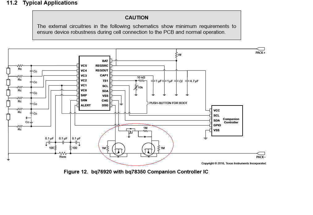
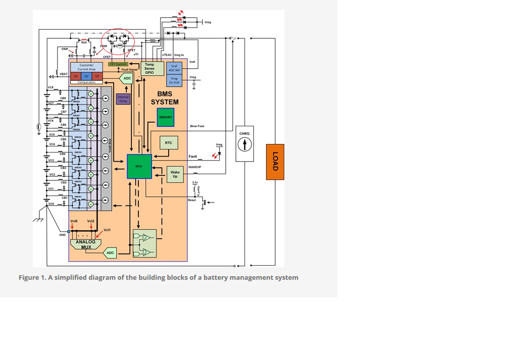
Hello there,

I would like to update you guys About my Project. I am working on the
schematic in FUSION 360 Electronics so far so good eventhough their
library isn't that great so I have been creating much of the components
myself which also help me to learn how it's done.

Anyway I would Need some help with the charging/Discharging circuit
implementation using two MOSFET like in the two attached files.


Since my Project is based on DC2026 + DC2259 Devboard I can't really
figure out how to implement this part. It will be a big help if you guys
can help me with a circuit diagram.


Many Thanks
Hello again,

Maybe I did not express myself properly.

I can't really figure out how to draw a schematic of a charging and
discharging process using two MOSFET with ATMEGA328P and
LTC6811(Monitoring IC). You guys can see that in my previous post the
bq76920(Monitoring IC) has a charge and discharge pins. How can I
implement the same Thing with the LTC6811 since it does not hape such
pins?

Many thanks
Solutions i see:
a. Use a different IC which has a shutdown functionality
b. build it up in a seperate circuit with some Comparators or even a µC.

I recommend solution a, since b can get tricky depending on your setup.
The Weasel wrote:
> Solutions i see:
> a. Use a different IC which has a shutdown functionality
> b. build it up in a seperate circuit with some Comparators or even a µC.
>
> I recommend solution a, since b can get tricky depending on your setup.

Hello The Weasel,

Thank you for your Suggestion. Do you have an example of an IC with a
shutdown functionality?

I can't really find any. I can't really figure out how to implement it.

I only found IC with thermal shutdown functionality and I don't really
get how they will work if they have to be used in the BMS.

I hope you guys can help me with a circuit diagram.

Many thanks
Hello Moi,

i can just highly recommend the bq769x series.
https://www.ti.com/lit/ds/symlink/bq76920.pdf?ts=1600409703323&ref_url=https%253A%252F%252Fwww.ti.com%252Fproduct%252FBQ76920
Available for 3-15 cells series with every shutdown function implemented
and configurable.

I also already used it in several professional applications and never
had any issues.
I personally recommend a version with a 3.3V output in combination with
an attiny as controller.

Just stick to the typical application diagram and you´re good to go.
Attached files:
-

Simple_CHG_DSCHG.png
6.3 KB
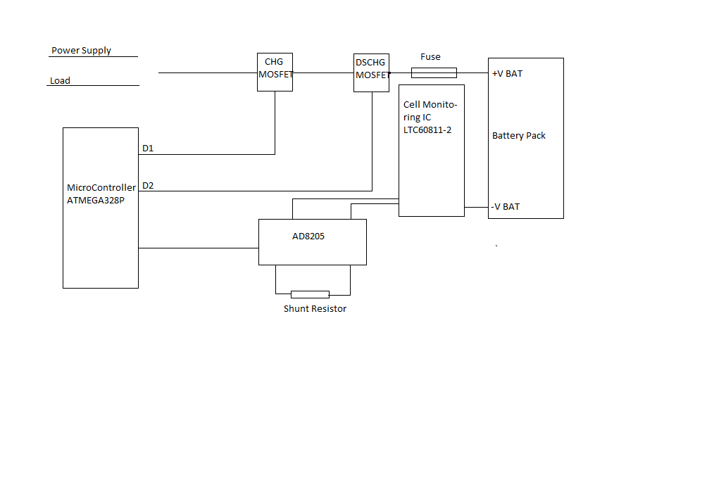
The Weasel wrote:
> Hello Moi,
>
> i can just highly recommend the bq769x series.
>
https://www.ti.com/lit/ds/symlink/bq76920.pdf?ts=1600409703323&ref_url=https%253A%252F%252Fwww.ti.com%252Fproduct%252FBQ76920
> Available for 3-15 cells series with every shutdown function implemented
> and configurable.
>
> I also already used it in several professional applications and never
> had any issues.
> I personally recommend a version with a 3.3V output in combination with
> an attiny as controller.
>
> Just stick to the typical application diagram and you´re good to go.

Hi The Weasel,

Thanks for the help. Actually I have to used LTC60811 IC.
Anyway I have been able to get some part and be able to get a good
schematic in my Knowledge I have attached the diagram.

I have some Questions regarding the different electronics part
Since my MOSFET are used in the positive battery side what will be the
MOSFET channel type? N or P I have read that N type are used for the
negative battery side but I have also seen the circuit where N-type are
used for the positive side.

My second Question is the Fuse value, since I have different battery
pack, 5S1P, 7S2P and 12S2P all Li-Ion what will be the best Fuse value
for each pack.

Many thanks
Attached files:
-

model.png
4.5 KB

Hello again,

I have been busy with another Project and could not work on my BMS
Project. Thankfully that project is done.

Back to my BMS I have made the charging and discharging schematic. I
would like you guys to have a look on it and let me know what you think.

I do have some Questions:

1 - Does this schematic need any modification?
2- When the MOSFET is OFF like during the charging process (Q3 = On and
Q4=        OFF) with the high current flowing through the Q4 Diode. I
think it will Damage Q4 as well as during the discharging process with a
much higher current than the charging process.

My idea of solving the Question 2 is to used two or more MOSFET in
parallel but I don't know if that will solve the Problem. I can't the
heatsink with MOSFET due to some size constraint on the PCB.

The gate Signals are from the Linduino I/O port

Any Suggestion is welcome.

Many thanks
Please log in before posting. Registration is free and takes only a minute.
Existing account
Do you have a Google/GoogleMail account? No registration required!
Log in with Google account
Log in with Google account
No account? Register here.