Guest
#6381644
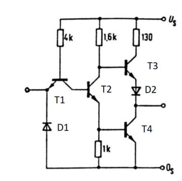
So basically this is a circuit with 2 diodes and it represents a NOT Circuit. But I don't understand the use of the Diode 2 (D2) here . Even without it the circuit represents still a NOT Circuit .
The use of the diode in this circuit
Guest
#6381644
So basically this is a circuit with 2 diodes and it represents a NOT Circuit. But I don't understand the use of the Diode 2 (D2) here . Even without it the circuit represents still a NOT Circuit .
Guest
#6381670
Without it, if T2 urns on and directs the current to T4, it may not pull down the base , and in effect the voltage between its emitter and base, of T3 low enough to turn it off. UBE(T2)+UBE(T4) must be < UCE(T4)+UBE(T4) and may not be the case. But UBE(T2)+UBE(T4) < UCE(T4)+Uf(D2)+UBE(T4) cetainly holds.
Guest
#6387921
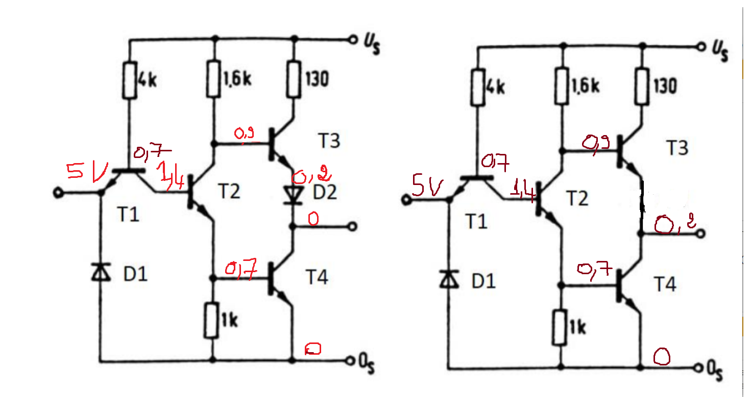
I'm not sure that I understand what you said . I'm kinda lost with the UBE UCE and UF symbols because I'm not familiar with them. Have a look at the screenshots that I made with/without Diode and tell me what I'm doing wrong . Plus I'd like to know what's UBE UCE and UF with the use of the voltage shown in my screenshots . That will be great to understand their meanings.
Guest
#6387922
As you can see in the screenshots . They both lead me to the same result. That's why I got confused
Guest
#6387942
Alex wrote: > They both lead me to the same > result. Why do you write 0V an the first output an 0.2V on the second ? Why is Uf just 0.2V ? Use realistic UBE, UCE and Uf values, for instance 0.7 0.2 and 0.7V or from a transistor data sheet or use LTSpice. The input transistor also has wrong 0.7V on base. It mainly works like 2 diodes, either directing the current thru the 4k7 resistor into the base of the T2 or into te input. I made a mistake in the formuals UBE(T2)+UBE(T4) must be < UCE(T4)+UBE(T3) and this will not be the case. But UBE(T2)+UBE(T4) < UCE(T4)+Uf(D2)+UBE(T3) cetainly holds
Guest
#6388019
> They both lead me to the same result.
Except that in the right diagramm T3 and T4 are both on and you have a
short. In the left, the 0.2V is not enough for the diode to conduct[1]
and no current flows through T3.
[1] especially as the output is also 0.2V and not 0 (the
collector-emitter voltage of T4) and hence the voltage across the diode
is ~0V.
Guest
#6389462
>Except that in the right diagramm T3 and T4 are both on and you have a >short. In the left, the 0.2V is not enough for the diode to conduct[1] >and no current flows through T3. So the diode D2 function would be on this case : Preventing a short circuit ?
Guest
#6389477
Alex wrote: > So the diode D2 function would be on this case : Preventing a short > circuit ? Yes, or in other words: allow the output circuit to work as intended. ReplyPlease log in before posting. |