peasant wrote:
> Careful with EN connection voltage, in case the smps controller is
> MP2315 and the EN connects directly to MP2315, as stated in my links
>
> MP2315 pins:
> AAM
> IN
> SW
> GND
> FB
> VCC
> EN/SYNC
> BST
>
> "ABSOLUTE MAXIMUM RATINGS
> (1)
> VIN ................................................–0.3V to +28V
> VSW........ –0.3V (-5V<10ns) to +28V (30V<10ns)
> VBST........................................................ VSW+6V
> All Other Pins ..................................-0.3V to +6V "
Had forgotten to write this, from my Protosupplies link, which may
apply:
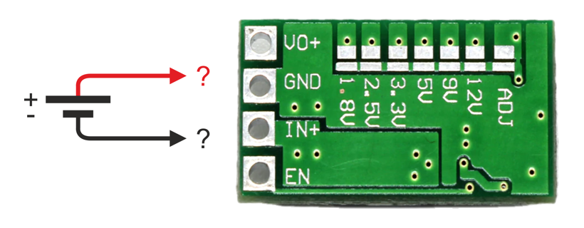
"Output Enable
The module has an EN (Enable) pin which is active HIGH.
"The module has this pin pulled high by default, so the module will
always be enabled and the EN pin can be left unconnected if the module
will always be enabled."