Giuseppe R. wrote:
> i didn't undestand the error on loop....
Which error?

The major problem here is, that you are "programming" VHDL like a
procedural programming language (e.g. C, Basic, Java). That will not
work. Never!

VHDL is a hardware DESCRIPTION language. And to DESCRIBE something you
must have a picture of it.

Start with a simple counter mapped to LEDs, simulate it and transfer it
to hardware. Have a look at the RTL-schematic. It shows you, how the
synthesizer did understand your DESCRIPTION.
Then change the counters code to count up while a button is pressed and
to count down while the button is released.
Then sync in and debounce the button and use it to count up your
counter.
Validate your solutions always with a testbench before going on
hardware, and have a look at the RTL schmematics.


A few words to some line of your code:
Have a look how a testbench invokes a "device under test". You will need
knowledge about components for that.

This here is nuts:
1 | if(clock'event and clock ='1') then
|
2 | if(reset'event and reset = '1') then
|
3 | ready <= '0';
|
This will never go into real hardware, because it is impossible in two
ways:
1. never ever you will have two rising edges of two signals at the
very same moment.
2. there is no "double clock flipflop" with two seperate clock inputs on
any FPGA/CPLD.

Having a second look, the whole code here is nuts:
1 | main: process
|
2 | begin
|
3 | ...
|
4 | end process main;
|
Its a process with no sensitivity list, it invokes three clocks, a latch
for parallel out and last, but not least: an async combinatorial reset
for ready. Each of them is bad, all of them together a valuable reason
for "you are fired!" ;-)
Giuseppe R. wrote:
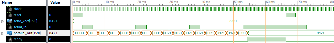
> -input clock 1200 HZ
> the input serial_in read 300 bit/s
Is the serial data synchronous to the input clock?
Looks like with every 4 clock cycles 1 data bit comes in.
Whats the systems clock? 1200Hz? Or xxMHz (with xx in 10..100)?
Whats the target hardware? FPGA? CPLD?
BTW:
Forget loops and variables. You don't need them here in this simple
project.