EmbDev.net

Forum: FPGA, VHDL & Verilog VHDL: counter checking


von maestros (Guest)


Rate this post
useful
not useful
I want to detect a external signal connection to a CPLD (only connected 
or not connected). My system clock is 1MHz and external signal is 4KHz. 
I have developed a logic that will detect rising edge of external signal 
and start a counter. If the counter is counting then external signal is 
connected and if the counter is not counting then external signal is not 
connected. I write the code but its not working, what is the problem? I 
am beginner in VHDL. Please help, How to check a counter running in 
vhdl?
1
library IEEE;
2
use IEEE.STD_LOGIC_1164.ALL;
3
use ieee.numeric_std.all;
4
use IEEE.STD_LOGIC_UNSIGNED.ALL;
5
6
entity SYNC_detection1 is
7
Port (  SYNC        : in  STD_LOGIC;
8
            CLK     : in  STD_LOGIC;
9
            EDGE        : out  STD_LOGIC;
10
            OUTPUT  : out  STD_LOGIC;
11
            BITSOUT : out  STD_LOGIC_VECTOR (3 downto 0)
12
                );
13
end SYNC_detection1;
14
15
architecture workingarchi of SYNC_detection1 is
16
17
signal SYNC_reg : std_LOGIC := '0';
18
signal SYNC_edge : std_LOGIC := '0';
19
signal TEMP : std_LOGIC := '0';
20
signal counter : STD_LOGIC_VECTOR (3 downto 0);
21
22
begin
23
24
SYNC_edge_p : process(CLK) 
25
begin
26
    if (rising_edge(CLK)) then
27
        SYNC_reg <= SYNC;
28
    end if;
29
end process;
30
31
SYNC_edge <= not SYNC_reg and SYNC;
32
33
counter_p: process(CLK) 
34
begin
35
    if (rising_edge(CLK)) then
36
        if SYNC_edge = '1' then
37
            counter <= counter + 1; 
38
                if (counter = "0000") then
39
                TEMP <= '1';
40
                end if;
41
        end if;
42
    end if;
43
end process;
44
45
OUTPUT <= TEMP;
46
BITSOUT <= counter;
47
EDGE <= SYNC_edge;
48
end workingarchi;

: Edited by Moderator
von Lothar M. (Company: Titel) (lkmiller) (Moderator)


Rate this post
useful
not useful
maestros wrote:
> use ieee.numeric_std.all;
> use IEEE.STD_LOGIC_UNSIGNED.ALL;
Never ever both together!
By ignoring this hint you will encounter some fairly strange errors due 
to multiple defined data types.

> I write the code but its not working, what is the problem? I am
> beginner in VHDL.
What do you expect? What does the code instead? How do you see that? 
What does your testbench look like?

> If the counter is counting then external signal is connected and if the
> counter is not counting then external signal is not connected.
A external signal is always connected in some way. Only its value 
changes. So do you mean "high" and "low" or '1' and '0'?

BTW:
The signal TEMP is only set once. Afterwards its never reset. That looks 
kind of strange...

BTW2:
Pls read the manual above each text box and use the [ vhdl ] tags for 
your code:
1
Reply
2
Rules — please read before posting
3
    Post long source code as attachment, not in the text
4
    :
5
Formatting options
6
    [vhdl]VHDL code[/vhdl]
7
    :

: Edited by Moderator
von maestros (Guest)


Rate this post
useful
not useful
Hi Lothar M., Thanks for your immediate reply and guidance. I will 
change my code accordingly. This is a part of my entire code written 
separately for easy understanding.

You said it correctly. A external signal is always connected in some 
way. In my case, when external signal is disconnected... the CPLD input 
pin is pulled 'high' and when the external signal is connected the CPLD 
will get 3.9KHz square wave as input. I want to create a 'status' for 
external signal weather it is connected or not by giving high or low 
repectively on CPLD pin.

Since it is incomplete code, i have not simulated the testbench. I stuck 
in the counter condition checking. How to check the counter running or 
counter stop, so that i can generate proper output. Please help.

von Lothar M. (Company: Titel) (lkmiller) (Moderator)


Attached files:

Rate this post
useful
not useful
maestros wrote:
> the CPLD input pin is pulled 'high' and when the external signal is
> connected the CPLD will get 3.9KHz square wave as input. I want to
> create a 'status' for external signal weather it is connected or not by
> giving high or low repectively on CPLD pin.
So the most easy way would be to check wether there is a change on the 
square-input now and then.

What I would do is nearly the same like you did:
Count up a counter with each system clock.
When the counter reaches a time of a little bit more than 1/(2*4kHz) = 
125µs = 125 system clock cycles  (lets assume here that the square 
signal is a perfect 50:50 square, otherwise it would be a rectangle and 
the time must be longer...) then there is no signal at the square input, 
so set "NoSignal" output is '1'.
Then check the square input for changes. When a change occures, reset 
the counter and additionally set the "NoSignal" output to '0'.

All in all it looks like this:
1
library IEEE;
2
use IEEE.STD_LOGIC_1164.ALL;
3
use ieee.numeric_std.all;
4
5
entity SYNC_det is
6
Port (  CLK      : in  STD_LOGIC;
7
        Square   : in  STD_LOGIC;
8
        SquareDetected : out  STD_LOGIC := '0'
9
                );
10
end SYNC_det;
11
12
architecture arch of SYNC_det is
13
14
   signal sqsr : std_LOGIC_vector(1 downto 0) := "11"; -- shift register for edge detection, default value: external pullup
15
   signal cnt : integer range 0 to 127 := 0;
16
17
begin
18
19
   counter_p: process(CLK) 
20
   begin
21
       if (rising_edge(CLK)) then
22
23
            -- never ever use a async input without sync'ing it to the system clock!
24
           sqsr <= sqsr(0)&Square;
25
           
26
           -- check for edges 
27
           if sqsr="10" or sqsr="01" then -- edge on SQUARE
28
               cnt <= 0;
29
               SquareDetected <= '1';
30
           else                               
31
               if cnt<127 then            -- count to highest value     
32
                   cnt <= cnt + 1; 
33
               else
34
                   SquareDetected <= '0'; -- end of counter reached --> timeout, no more edges 
35
               end if;
36
           end if;
37
38
       end if;
39
   end process;
40
41
end arch;

And the description above togehter with this testbench...
1
LIBRARY ieee;
2
USE ieee.std_logic_1164.ALL;
3
4
 
5
ENTITY tb_sd IS
6
END tb_sd;
7
 
8
ARCHITECTURE behavior OF tb_sd IS 
9
10
    COMPONENT SYNC_det
11
    PORT(
12
         CLK : IN  std_logic;
13
         Square : IN  std_logic;
14
         SquareDetected : OUT  std_logic
15
        );
16
    END COMPONENT;
17
    
18
   signal CLK : std_logic := '0';
19
   signal Square : std_logic := '1';
20
21
   signal sq    :  std_logic := '1'; -- default value = 'high' due to pullup
22
   signal sqen  :  std_logic := '1';
23
24
   signal SquareDetected : std_logic;
25
26
BEGIN
27
   uut: SYNC_det PORT MAP (
28
          CLK => CLK,
29
          Square => Square,
30
          SquareDetected => SquareDetected
31
        );
32
33
   clk  <= not clk after 500 ns;   -- 1MHz system clock
34
   
35
   sq   <= not sq after 125 us;    -- 4kHz square wave 
36
   sqen <= not sqen after 2250 us; -- enable for the square wave signal
37
   Square <= sq and sqen;
38
39
END;
... results in the waveform in the screenshot. Looks ok for me... ;-)

: Edited by Moderator
von maestros (Guest)


Rate this post
useful
not useful
Hello Lothar M., Your code is perfectly  working, I have tested it on 
hardware also. Thanks a lot for your help and prompt reply.

von Lothar M. (Company: Titel) (lkmiller) (Moderator)


Attached files:

Rate this post
useful
not useful
maestros wrote:
> Your code is perfectly  working, I have tested it on hardware also.
Nice to hear.
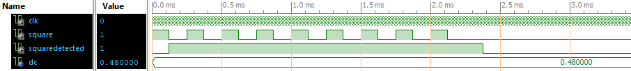
A hint: check out the symmetry of your square wave. When its changing a 
little bit from 50:50 to 48:52, then you will get short spikes on the 
SquareDetected output, because there is only a little margin on the 
counter (from 125 to 127). See WF_SD_DC48.PNG for that.
To get this waveform I changed the test bench a little to invoke the 
duty cycle in the 4kHz signal:
1
   :
2
   constant dc : real := 0.48;
3
   :
4
BEGIN
5
   :
6
   process begin
7
      sq <= '1';
8
      wait for dc * 250 us;
9
      sq <= '0';
10
      wait for (1.0-dc) * 250 us;
11
   end process;
12
   :

To be much more tolerant there it would be best to increase the top 
value of the counter to 255:
1
   :
2
   signal cnt : integer range 0 to 255 := 0;
3
   :
4
               if cnt<255 then            -- count to highest value
5
   :
The reaction to detect a missing 4kHz square wave signal is then delayed 
by  129us. See WF_SD_DC48_cnt255.PNG at around 2.2ms.

: Edited by Moderator
Please log in before posting. Registration is free and takes only a minute.
Existing account
Do you have a Google/GoogleMail account? No registration required!
Log in with Google account
No account? Register here.