Hi, I have a problem with Active HDL.
So I was given a 5 variable function with truth table.
I need to implement it on 4to1 mux and 2AND elements.
When I test only the mux it works perfectly, but when I combine it with
other mux and 2AND gate it doesn`t work..

Here is the code of mux:
1
libraryIEEE;
2
useIEEE.STD_LOGIC_1164.all;
3
useIEEE.std_logic_unsigned.all;
4
5
entitymux_4_to_1is
6
port(
7
E:inSTD_LOGIC;
8
D:inSTD_LOGIC_VECTOR(15downto0);
9
A:inSTD_LOGIC_VECTOR(3downto0);
10
F:outSTD_LOGIC
11
);
12
endmux_4_to_1;
13
14
architecturemuxofmux_4_to_1is
15
16
begin
17
process(E)
18
begin
19
ifE='1'then
20
F<=D(Conv_Integer(A));
21
endif;
22
endprocess;
23
endmux;
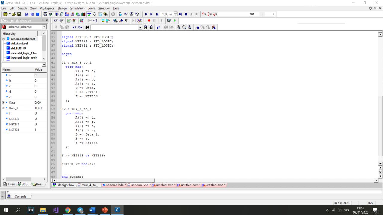
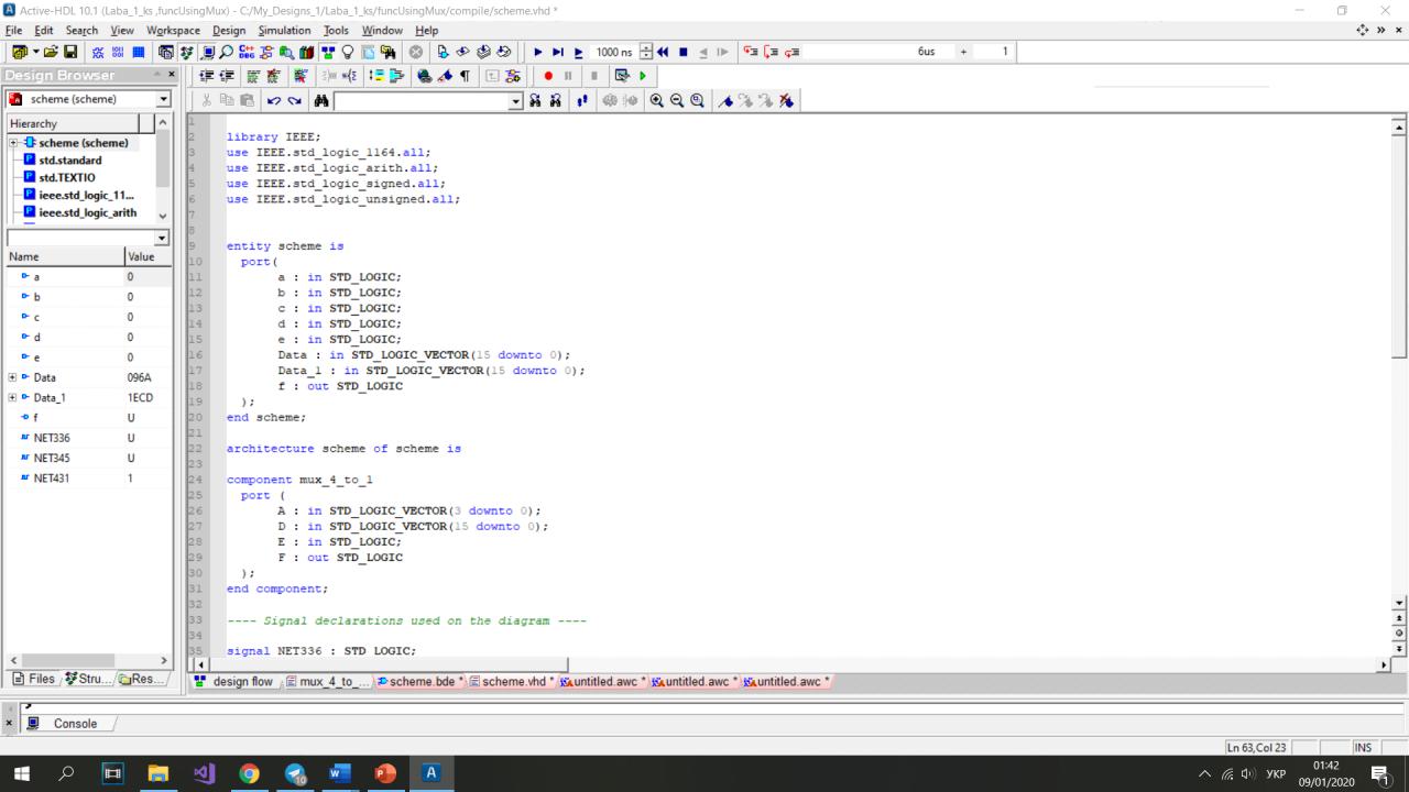
And the mux`s combined code generated by Active HDL from my block
diagram:
1
libraryIEEE;
2
useIEEE.std_logic_1164.all;
3
useIEEE.std_logic_arith.all;
4
useIEEE.std_logic_signed.all;
5
useIEEE.std_logic_unsigned.all;
6
7
8
entityschemeis
9
port(
10
a:inSTD_LOGIC;
11
b:inSTD_LOGIC;
12
c:inSTD_LOGIC;
13
d:inSTD_LOGIC;
14
e:inSTD_LOGIC;
15
Data:inSTD_LOGIC_VECTOR(15downto0);
16
Data_1:inSTD_LOGIC_VECTOR(15downto0);
17
f:outSTD_LOGIC
18
);
19
endscheme;
20
21
architectureschemeofschemeis
22
23
componentmux_4_to_1
24
port(
25
A:inSTD_LOGIC_VECTOR(3downto0);
26
D:inSTD_LOGIC_VECTOR(15downto0);
27
E:inSTD_LOGIC;
28
F:outSTD_LOGIC
29
);
30
endcomponent;
31
32
---- Signal declarations used on the diagram ----
33
34
signalNET336:STD_LOGIC;
35
signalNET345:STD_LOGIC;
36
signalNET431:STD_LOGIC;
37
38
begin
39
40
U1:mux_4_to_1
41
portmap(
42
A(0)=>d,
43
A(1)=>c,
44
A(2)=>b,
45
A(3)=>a,
46
D=>Data,
47
E=>NET431,
48
F=>NET336
49
);
50
51
U2:mux_4_to_1
52
portmap(
53
A(0)=>d,
54
A(1)=>c,
55
A(2)=>b,
56
A(3)=>a,
57
D=>Data_1,
58
E=>e,
59
F=>NET345
60
);
61
62
f<=NET345orNET336;
63
64
NET431<=not(e);
65
66
67
endscheme;
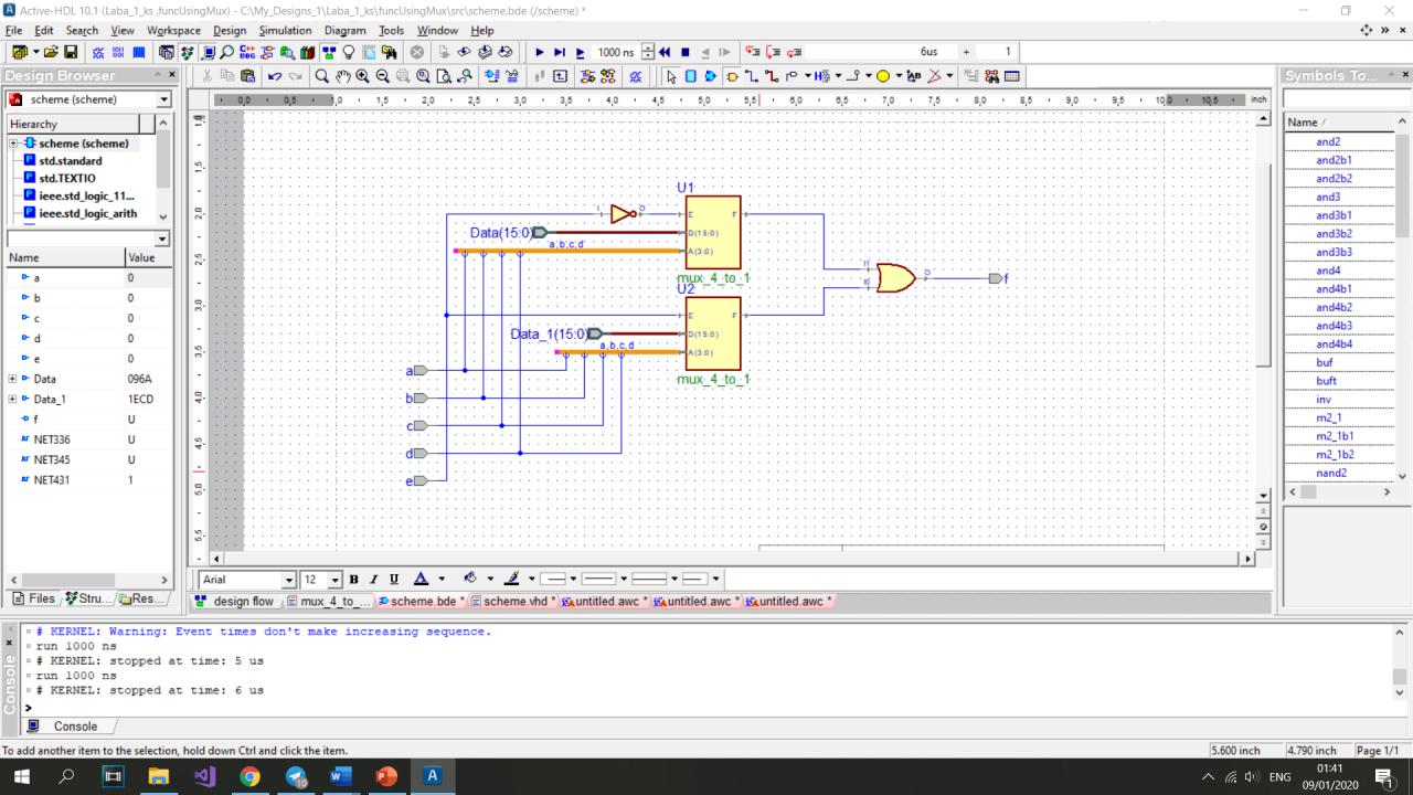
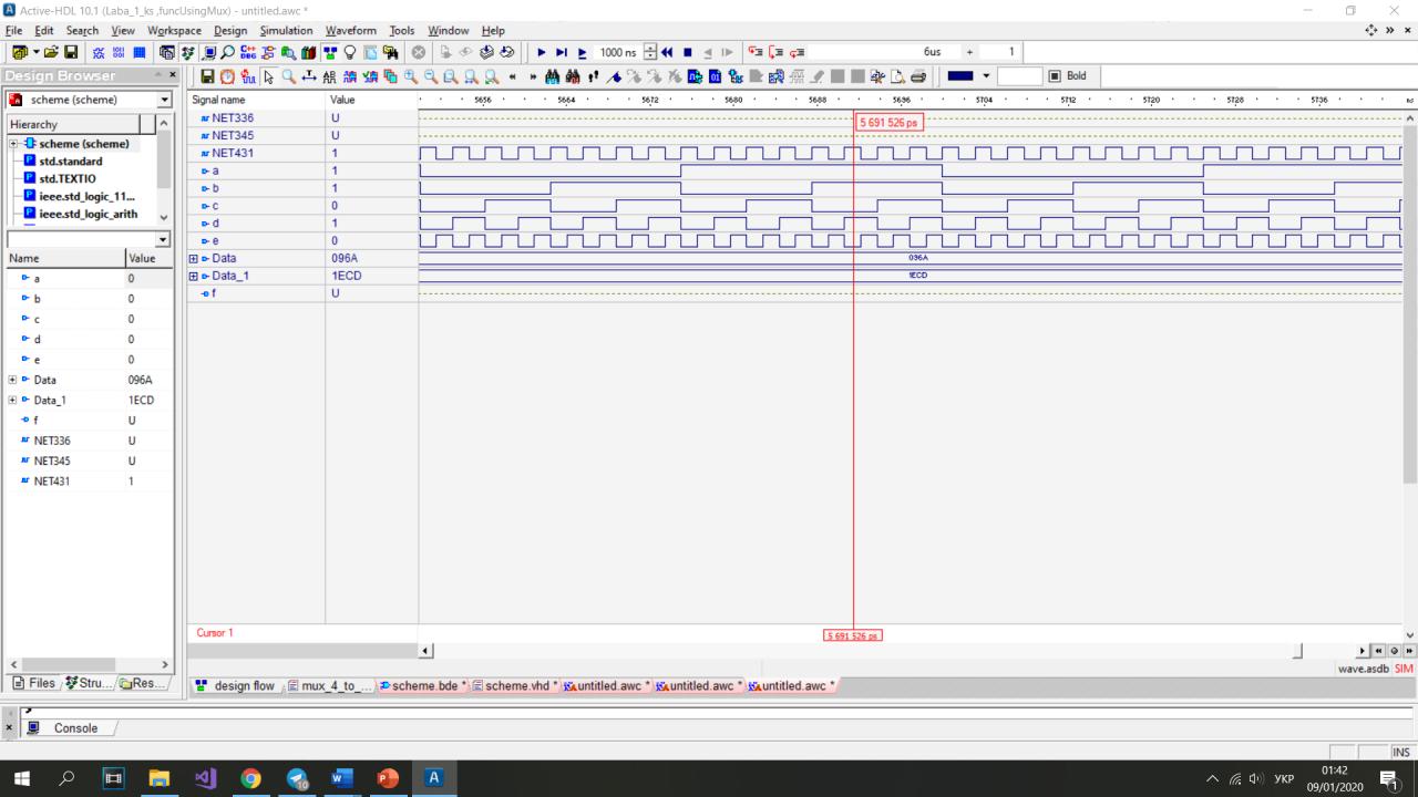
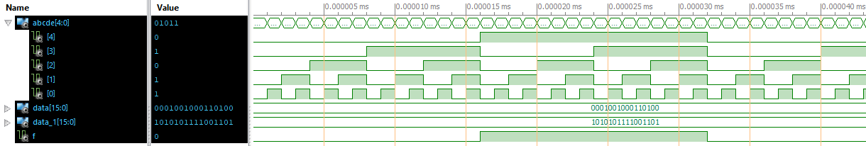
Also I include screenshots of block diagram and waveform.
Thanks on advance for your help!
And sorry if question is stupid.
Yuriy B. wrote:> And the mux`s combined code generated by Active HDL
Indeed? Strange...
> use IEEE.std_logic_arith.all;> use IEEE.std_logic_signed.all;> use IEEE.std_logic_unsigned.all;
Using both the unsigned an signed math libs will bring the synthesizer
into trouble when encountering an arithmetic operation. Additionally in
that module neither of the three math libs is needed at all!
> but when I combine it with other mux and 2AND gate it doesn`t work..
What do you expect and what do you get instead? And how do you see that?
> Also I include screenshots of block diagram and waveform.
What can we see there? And what should be instead of that?
> Here is the code of mux:
1
ifE='1'then
2
F<=D(Conv_Integer(A));
3
endif;
Thats very bad coding style: because you don't have a default value for
F or an "else" assigning a value to F you will get a latch. A latch
alone is bad enough, but a accidently latch is much worse!

> f <= NET345 or NET336;
Think about the previous lament about latches and have a close look to
this OR gate.

And then try that:
1
ifE='1'then
2
F<=D(Conv_Integer(A));
3
else
4
F<='0';
5
endif;
or that:
1
F<='0';
2
ifE='1'then
3
F<=D(Conv_Integer(A));
4
endif;
And to get the "force-simulation-orgy" working complete the sensitivity
list of the process:
1
process(E,A,D)
Because the sensitivity list MUST include every signal that may alter
the output/result of the process.

> When I test only the mux it works perfectly
Really? ... With that incomplete sensitivity list? ... Strange!
Just to twist the fingers a little i setup a testbench and simulated the
design with a complete (e,a,d) an the incomplete (e) sensitivity list
like that:
1
:
2
:
3
begin
4
process(E,a,d)-- complete sensitivity list
5
begin
6
F<='0';-- default value
7
ifE='1'then
8
F<=D(Conv_Integer(A));
9
endif;
10
:
11
:
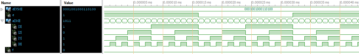
Additionaly I added a screenshot with the correct senitivity list, but
no default value for f.

And for all of the screenshots I added the testbench. Its much easier
and protable(!!) than twiddling around with that force-thing in the
simulator.
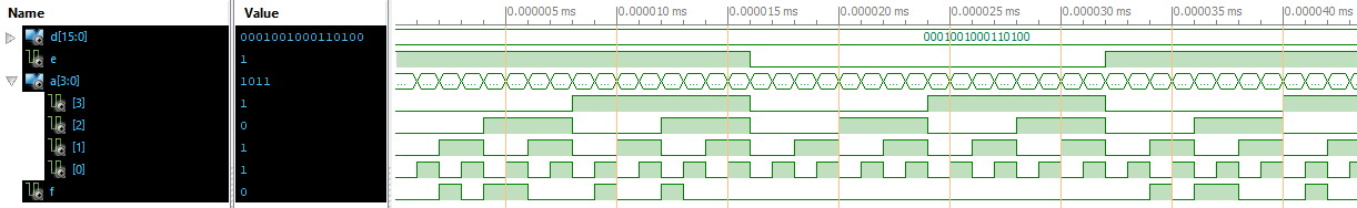
Yuriy B. wrote:> When I test only the mux it works perfectly
To finish up, I did a simulation of the mux itself also. I setup a
simple testbench for the 4-1 mux and simulated the original "perfectly
working" code.
As I expected, this code does not do what it should due to the
incomplete sensitivity list. And the E input does not do what it should
do due to the missing default value.
With the correct code the mux works really perfectly... ;-)
I appericate Your reply!
But when I changed the mux code it still doesn`t work..
Still the same problem

Here`s the code of mux i corrected as You said:
1
libraryIEEE;
2
useIEEE.STD_LOGIC_1164.all;
3
useIEEE.std_logic_unsigned.all;
4
5
entitymux_4_to_1is
6
port(
7
E:inSTD_LOGIC;
8
D:inSTD_LOGIC_VECTOR(15downto0);
9
A:inSTD_LOGIC_VECTOR(3downto0);
10
F:outSTD_LOGIC
11
);
12
endmux_4_to_1;
13
14
architecturemuxofmux_4_to_1is
15
16
begin
17
process(E,A,D)
18
begin
19
F<='0';
20
ifE='1'then
21
F<=D(Conv_Integer(A));
22
endif;
23
endprocess;
24
endmux;
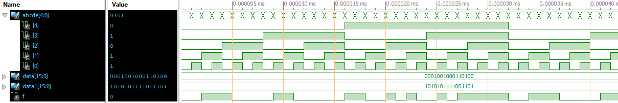
And the device code generated by active hdl, and by the way, when I
remove those not needed libraries and hit compile they comeback, don`t
know why, compiler adds them by itself..
Yuriy B. wrote:> Those lines aren`t working:
Can't see no problem there. Those are just signal assignments. Theres no
funcionality at all.
> Still the same problem
I took your code and my testbench and did therein some changes with
some letters and underlines and put them both together in the simulator
and found out: its working fine on Xilinx ISIM. I'm absolutely sure its
working on Aldec also, but my license ended, I must get a new one to
prove it ;-)
> when I remove those not needed libraries and hit compile they comeback,> don`t know why, compiler adds them by itself..
Its compiled out of that schematic. As a lucky guy I don't use any
graphic editor in any toolchain. And I don't use that signal forcing in
simulation either. Just plain VHDL from top to bottom. It can all I
need. Obviously that way I encounter less problems.
And thats what I urge you: forget those graphical interfaces, write the
testbench and the interconnect in VHDL.
BTW:
> photo_2020-01-09_18-15-05.jpg
Pls post screenshots as png files. They don't have any artifacts and are
clearly readable.
https://en.wikipedia.org/wiki/Compression_artifact
BTW2:
A(0) => d,
A(1) => c,
A(2) => b,
A(3) => a,
Thats a really strange bit order. You get a knot in the brain twiddling
it out.