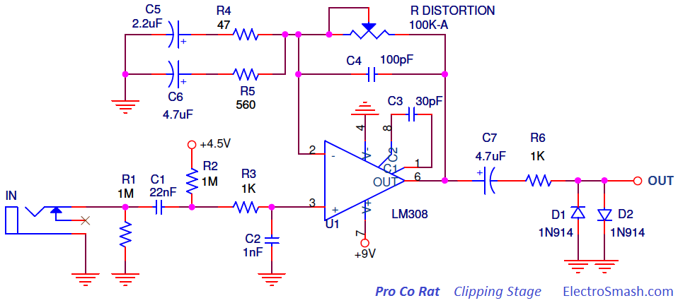
Hey there,
I have some weird problems with one of my builds.
It's basically the RAT schematic with some changes in the values of
resistors and capacitors. A tonestack and a buffer behind it, but that's
not the problem.

I get signal at the non-inverting pin of the JRC4558. Now the weird
thing. On the output pin I get a signal when the gain pot in the
feedback path (changed it to 250kA) is at 0 and also if I turn it up a
little, then it even acts the way I want it to and increases gain. But
at some point the tone cuts off and stays that way no matter if I turn
it to 10 or else. It doesn't really cut off, but it can only be heard if
I heavily increase the input volume. It seems like there is a zener
somewhere, cuts the signal when it reaches a certain point. There is one
between +9V and GND in the power supply filter circuit to prevent damage
in a swapped polarity case, but that shouldn't be the reason. The diodes
(used red LEDs) light up when the pot is somewhere in between 0 and
until the point tone cuts off. Also realized tone at inverting input
becomes very bassy when it hits that point.
The voltage measurements are the way I expected them to, unless one
thing. There are 5V steady on the inverting pin and 5-6V on output pin
depending on the pot(6V when maxed). But only if the IC is in its
socket. I don't really get why?! The tonestack is doing his job and I
already changed the opamp.
What could it be? Very appreciate any kinds of suggestions.

PS: There is a very very small range between maxed tone and no tone
where it gets kind a distorted, like it's dying there. Don't know if
that helps. :D
Attached files:
Luca wrote:
> with some changes in the values of resistors and capacitors.
> The diodes (used red LEDs)
Thats kinda major difference to the original schematic. It seems best,
that you post your schematic with your values and additionally a pic
of how you built it. Sounds like the whole thing oscillates wildly...

Do you have a scope at hands?
Hey, unfortunately I don't have a scope at hands.
The changes are: 47p instead of 100p, the two resistors and caps in the
feedback path going to gnd are basically just adjusted to the pot
change, so same freq. cuts here.(no more electrolytic caps) And I also
change the 1nF right in front of the opamp with a 3.3nF one to prevent
the oscillation that was going on there.(figured that out in one of my
earlier builds, that are quite the same and just work fine)
show your real and layout schematic.

what pins did you use on the 4558?
Attached files:
-

image10.png
180 KB -

20190924_141608_Film1.jpg
240 KB
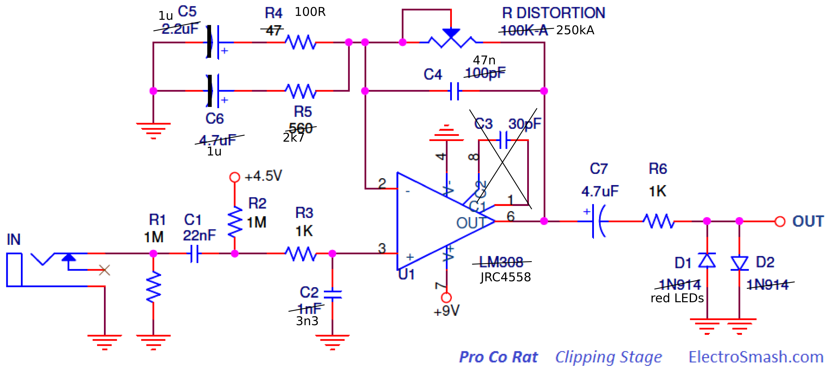
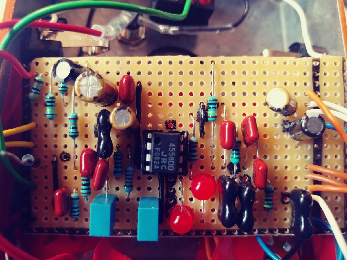
Don't really have a schmematic. But as the "same" circuit worked before
and I didn't spot any easy mistakes I guess it must be something that
can not be seen by looking at my build. Maybe someone has a idea what
could cause such problems and then I can focus on that part. But of
course I can give you an updated schematic and a picture of my real
build, as I maybe have overlooked some easy mistakes. The green wire is
the input, the top yellow one is Gain 1, the other Gain2&3. Red +9V,
Black GND. I triple checked all the wires going to the pots and else,
that shouldn't be the mistake.

PS: I disconnected the zener, but it's still the same.
Oh sorry, forgot to change that in the schematic. Of course 6 becomes 1
here.

Also realized the volume pot on my guitar creates some cracking and
noise by turning it up an down, sometimes even the LEDs light up.
what about pin7?

where is your virtual ground comming from?

only solution i see to fix this build:
re-draw a complete new schematic by hand from your actual build.
then check what's wrong.
Luca wrote:
> Oh sorry, forgot to change that in the schematic.
What happened to the second half of the 4558?

> Also realized the volume pot on my guitar creates some cracking and
> noise by turning it up an down
Then theres going DC trough it. Measure the DC voltage at the "In" plug
vs. GND. It should be 0V.

> and a picture of my real build
Pls also flip it over and take a pic. The actual wiring is hidden
there...   ;-)
Attached files:

V+ going to pin 8, GND to pin 4. Here's a layout of the power supply.
+4.5V comes in trough a 1M resistor after the first 22n cap. Got about
9V at pin 8 and 2.x at pin 3. That seems to be ok. But is it normal to
have 5V at pin 2? It must be caused by the opamp as I have 0V there when
it's not in the socket. Pin 5 also has a connection to virtual ground
and 6 and 7 are connected so the second opamp acts like a buffer.
There are 5V at input pin :o . I guess that could be the problem, but
also only when the IC is not in its socket.
i say it again:
re-draw a complete new schematic by hand from your actual build.
then check what's wrong.

i'm out until then, it's a waste of time otherwise.
Luca wrote:
> Sorry 5v at input when IC IS in its socket, otherwise 0V
With open input? Without a guitar connected?
Then you have some wiring problems or a defective C1. At least...

Luca wrote:
> Got about 9V at pin 8 and 2.x at pin 3. That seems to be ok. But is it
> normal to have 5V at pin 2.
As long as the 4558 is working as it should, you have the very same
voltage at pin 2 and pin 3. Thats the job of the 4558: to keep the
difference between them both zero.
R4 versus your pot allows an amplification of up to 250000. I doubt that
your OP-amp can follow that.

Regarding the "bassy" sound:

The 47nF capacitor has 340Ω at 10kHz and 34000Ω at 100Hz. So this
capacitor weakens the high frequencies. If your pot is at 0Ω, the
capacitor has no effect because it is completely bypassed by the pot.
But on the other hand when your pot is 250kΩ, then only a very small
part of the signal hoes through the pot, most part of the signal goes
through the capacitor so its frequency-dependant resistant become
noticable.
> up to 250000

Sorry, too many zeroes. It is up to 2500, this should be supported by
any OP-amp.
Lothar M. wrote:
> With open input? Without a guitar connected?
> Then you have some wiring problems or a defective C1. At least...

Yes without a guitar connected.

Lothar M. wrote:
> As long as the 4558 is working as it should, you have the very same
> voltage at pin 2 and pin 3. Thats the job of the 4558: to keep the
> difference between them both zero.

Pin 3 has the 2.5V through bias, Pin 2 still gets 5V but I don't know
where it comes from, must be from inside the IC cause it's only there
when it's connected. Already changed the IC but same result.
Another weird thing: when i measure voltage between gnd and pin 3 the
gain pot works like a dimmer for the LEDs in the upper range. They're
brightest when it's maxed.

stefanus wrote:
> Regarding the "bassy" sound:
>
> The 47nF capacitor has 340Ω at 10kHz and 34000Ω at 100Hz. So this
> capacitor weakens the high frequencies. If your pot is at 0Ω, the
> capacitor has no effect because it is completely bypassed by the pot.
> But on the other hand when your pot is 250kΩ, then only a very small
> part of the signal hoes through the pot, most part of the signal goes
> through the capacitor so its frequency-dependant resistant become
> noticable.

It's a 47pf one, it's only there to cut off the useless very high freq.
and prevent the circuit from oscillation.
Luca wrote:
> Pin 3 has the 2.5V through bias, Pin 2 still gets 5V but I don't know
> where it comes from

As long as the Opamp doesn't show the voltage of the VCC/2 rail on all
of its  inputs and outputs without signal, the opamp is not working
correctly. Exchange it with a known good working part. Before inserting
the new chip make sure theres VCC/2 on the non-inverting input. If thats
the case, a good opamp will then show this voltage on all its inputs and
outputs.
matzetronics wrote:
> As long as the Opamp doesn't show the voltage of the VCC/2 rail on all
> of its  inputs and outputs without signal, the opamp is not working
> correctly. Exchange it with a known good working part. Before inserting
> the new chip make sure theres VCC/2 on the non-inverting input. If thats
> the case, a good opamp will then show this voltage on all its inputs and
> outputs.

I put in another IC of one of my working builds, still the same.

I don't get it, the only thing connected to the input that will let DC
pass is the 1M resistor to ground
Found it!!!!

A extreme tiny piece of a strand connected the In rail and the one
beneath it(which connects between the 2k7 resistor and the 1u cap).
A massive thanks to all of you for helping me find the problem. So I
knew where to look at. You guys are great!
Hello....What slaughters sound quality in operation amps is called
hybrid twisting - this happens at mid-voltage when the current yield
changes bearings (distinctive yield semiconductors are turned on). It
will in general be a fixed degree of mutilation voltage- - not truly
recognizable at rail to rail yield, however truly perceptible at low
sign levels. This is an issue in modest operation amps like the LM324
that are not so much planned for sound.

I genuinely don't have a clue what to search for in the specs to evade
this- - the experience of others here is essential in operation amp
determination - additionally there are actually countless reasonable
gadgets.
Please log in before posting. Registration is free and takes only a minute.
Existing account
Do you have a Google/GoogleMail account? No registration required!
Log in with Google account
Log in with Google account
No account? Register here.