Hello,

I need to write a Finite State Machine (FSM) in VHDL code and  want to
have several computations being processed at the same time (a standard
pipeline). In every state I have several operations to be calculated and
I employ registers for the result of each one. I strongly need to reuse
these registers, for example: Register 1 is filled in State 1 (as a
result of a multiplication) and it is used in the State 2 and State 3
(as parameter of other operations), then in the State 4, I want to save
a new operation result (another multiplication) in Register 1 reusing
it.

My code works in Simulation in Xilinx Vivado 2019, but when I implement
the desing in a real FPGA (Basys 3 Artix-7) it doesn't work. I realized
that the problem is that the correct values are not saved when I reuse
the registers. Sometimes, the first time I reuse them, they keep the
correct value, but already in the second reuse in later FSM states, the
stored values are not correct, I mean, they do not correspond to the
result of the operation that I am trying to save in the register.

Next, an example of my FSM design:
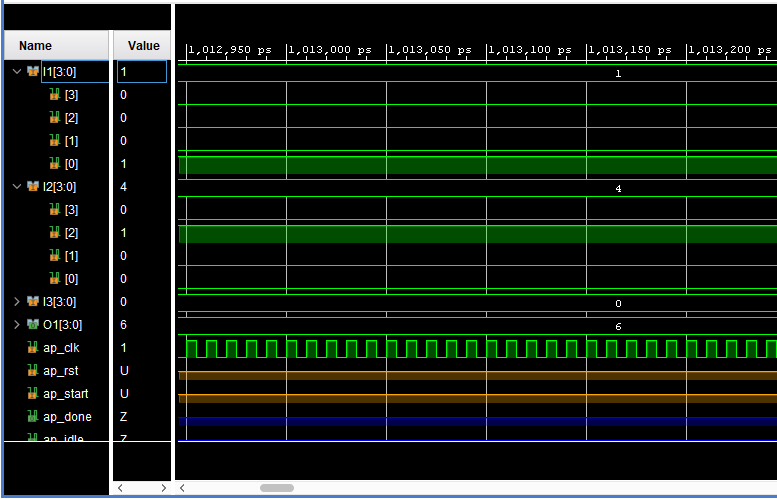
In this case, I want to reuse R1 and it works well in Simulation with
Xilinx Vivado (1 + 4 + 0 + 1 = 6):
Figure 1.
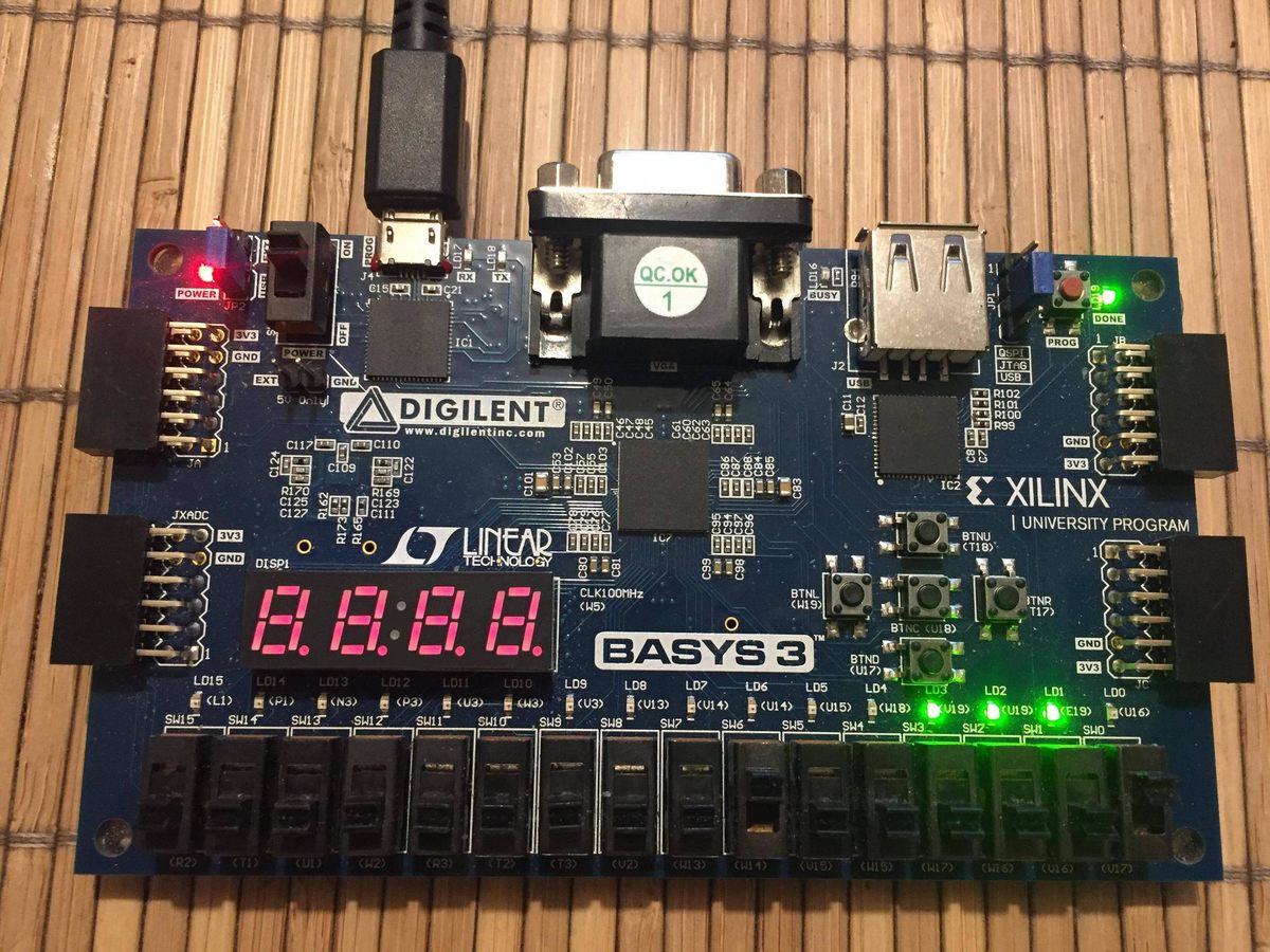
Unfortunately, in the Basys 3 FPGA Artix-7 I don't get the correct
results:
Figure 2.
In this figure, I show the Case 10 in a FPGA, it should get 6 (1 + 4 + 0
+ 1) as result, but it gets 14 instead:
Figure 3.
In the tests that I have been doing I realized that it works better when
before assigning a new value in the registry the value of the record is
made zero before reassigning a value, for example:
1
WHENstate_3=>
2
R4<="0000"
3
IF(R4="0000")then
4
R4<=ALU(Op=>7,A=>R2,B=>R3,C=>"0000");
5
Flag<=3;
6
IF(Flag=3)THEN
7
state_future<=state_4;
8
ENDIF;
9
ENDIF;
Using this form I can reuse a register once, the second time I want to
reassign a value to the register, incorrect values are shown in the
output.

I declarated the registers as SHARED VARIABLE and SIGNALS and I have the
same problem with both.

I appreciate any suggestion or idea, thanks a lot.
Darian Reyes wrote:> OP_FSM : PROCESS (state_present)
This sensitiviy list is incomplete! I2, I3, R1 and this strange "Flag"
is missing. Therefore the simulation is WRONG! The toolchain tells you
that with a "Info" or a "Warning"...
What the heck is that thing with this "Flag"? Where did you see this
kind of coding?
One word about "variables" espacially "shared variables": you don't need
both of them at all.
You have implemented the ALU logic completely as a large combinatorial
function. This will result in an incredible large and incredible slow
unstructured sea of connected lookup tables.
For example: One of the alu function is a division. Make yourself
familar with division algorithms for hardware and then try to imagine
how they would behave if implemented without any pipelining or
sequential elements.

Ok, let us assume for the moment, that your alu is functionally
correct. Anyway, it will be slooooow. On the other hand, your state
machine does a state transition in every clock cycle. So how fast is
your clock? Lets say, 20MHz? That is, your alu has 50ns of time for
computation. This is fine for AND and XOR, but surely not for
unpipelined MULT and DIV.

Did you set any timing constraints in your design? Does Vivado know
about which frequency your design is intended to run at? If yes, does
the timing report complain about any timing violations?

When looking at your code, I don't see a VHDL design. I see a piece of
software that somebody has translated into VHDL statements. There is a
good reason why the simulation is correct, and the hardware fails: It is
a simulation model, not a hardware design. There is almost no chance for
the synthesis tools to translate this into an efficient hardware.

Before starting with VHDL, learn about digital design, how to implement
arithmetics if you only have gates and flipflops. Expect that division
in hardware is much more complicated than just writing a "/". Then come
back to VHDL and write your model completely new. Do not use VHDL to
implement an algorithm. You will fail with that (everybody would fail
with that, but some people persistently reject to understand that).
Develop an architecture first, and then use VHDL to describe this
architecture.
Vancouver wrote:> use VHDL to describe this architecture.
Just to confirm that statement. VHDL ist NOT a programming language.
Its a hardware description language. So there must be a kind of
"picture" (at least in brain) that can be described with VH*D*L.
Afer syntheszing your desgin have a look for the RTL-schematics and chek
whether it matches your "picture" or not. If not, then you have to
change your VHDL description until its alsmost the same.
> not for unpipelined MULT
The SPARTAN 3 FPGA on the eval board has hardware multipliers that can
handle up to 18x18 bit data width:
https://www.xilinx.com/support/documentation/application_notes/xapp467.pdf
With the description above and its 4 bit input they can be used and the
20MHz will cause no problem here.
>>> (A_int / B_int)> division in hardware is much more complicated than just writing a "/"
Indeed!