EmbDev.net

Forum: FPGA, VHDL & Verilog PWM with 4-bits control in Verilog


von Cm Y. (cmyang)


Attached files:

Rate this post
useful
not useful
Greetings,

I'm designing a PWM module,with a 4 bits control.
My specs,a 4-bits input control,input clock 50MHz,
a single bit output PWM_o,

when control changes,the duty cycle of PWM_o changes,
like control = 0,PWM_o = 0;Control = 1,PWM_o = 6.25%...increase 6.25% 
each time(meaning that PWM_o should be wider and wider each time it 
outputs when Control increase).Desired result should be like marked with 
red rectangular in the first photo.

I've tried so many version of ways to write it,I've noticed the common 
issue is that my Control changing too fast and I don't know how to delay 
it,I need to make the Control change after 16 pulses of input Clock,I 
just can't figure out how to do it...

I don't understand how to delay a set of multiple bits of input...

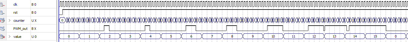
Here down below are my attempting,my attempting's output is almost 
correct,but just the issue with the Control..
Noted: Control is named as `value` in the codes;

Attempting 1:
1
 module pwm_c(clk,value,rst,PWM_out,counter,rst);
2
input clk,rst;
3
input [3:0] value;
4
output PWM_out;
5
reg PWM_out;
6
7
output reg [3:0]counter;
8
9
10
always@(posedge clk)
11
    begin
12
        if(!rst)
13
            counter <= 4'd0;
14
        else
15
            counter <= counter + 4'd1;
16
    end
17
18
always@(counter or value)
19
    begin
20
        if(value == 4'd0)
21
            PWM_out = 1'b0;
22
        else if(value == 4'd1)
23
            PWM_out = (counter >=4'd1) ? 1'b0:1'b1;
24
        else if(value == 4'd2)
25
            PWM_out = (counter >=4'd2) ? 1'b0:1'b1;
26
        else if(value == 4'd3)
27
            PWM_out = (counter >= 4'd3) ? 1'b0:1'b1;
28
        else if(value == 4'd4)
29
            PWM_out = (counter >= 4'd4) ? 1'b0:1'b1;
30
31
        else if(value == 4'd5)
32
            PWM_out = (counter >= 4'd5) ? 1'b0:1'b1;
33
        else if(value == 4'd6)
34
            PWM_out = (counter >= 4'd6) ? 1'b0:1'b1;
35
        else if(value == 4'd7)
36
            PWM_out = (counter >= 4'd7) ? 1'b0:1'b1;
37
        else if(value == 4'd8)
38
            PWM_out = (counter >= 4'd8) ? 1'b0:1'b1;
39
40
41
        else if(value == 4'd9)
42
            PWM_out = (counter >= 4'd9) ? 1'b0:1'b1;
43
        else if(value == 4'd10)
44
            PWM_out = (counter >= 4'd10) ? 1'b0:1'b1;
45
        else if(value == 4'd11)
46
            PWM_out = (counter >= 4'd11) ? 1'b0:1'b1;
47
        else if(value == 4'd12)
48
            PWM_out = (counter >= 4'd12) ? 1'b0:1'b1;
49
50
        else if(value == 4'd13)
51
            PWM_out = (counter >= 4'd13) ? 1'b0:1'b1;
52
        else if(value == 4'd14)
53
            PWM_out = (counter >= 4'd14) ? 1'b0:1'b1;
54
        else if(value == 4'd15)
55
            PWM_out = (counter >= 4'd15) ? 1'b0:1'b1;
56
57
58
        else
59
            PWM_out = 1'b0;
60
    end 
61
 endmodule

Attempting 2:
1
module pwm_c(clk,value,rst,PWM_out,counter);
2
input clk,rst;
3
input wire [3:0] value;
4
output PWM_out;
5
reg PWM_out;
6
7
output reg [3:0]counter;
8
9
10
  
11
12
always@(posedge clk)
13
    begin
14
        if(!rst)
15
            counter <= 4'd0;
16
        else
17
            counter <= counter + 4'd1;
18
    end
19
20
always@(counter or value)
21
    begin
22
        if(value == 4'd0)
23
            PWM_out = 1'b0;
24
        else if(value == 4'd1)
25
            PWM_out = counter<2;
26
        else if(value == 4'd2)
27
            PWM_out = counter<2;
28
        else if(value == 4'd3)
29
            PWM_out = counter<2;
30
        else if(value == 4'd4)
31
            PWM_out = counter<2;
32
33
        else if(value == 4'd5)
34
            PWM_out = counter<4;
35
        else if(value == 4'd6)
36
            PWM_out = counter<4;
37
        else if(value == 4'd7)
38
            PWM_out = counter<4;
39
        else if(value == 4'd8)
40
            PWM_out = counter<4;
41
42
43
        else if(value == 4'd9)
44
            PWM_out = counter<6;
45
        else if(value == 4'd10)
46
            PWM_out = counter<6;
47
        else if(value == 4'd11)
48
            PWM_out = counter<6;
49
        else if(value == 4'd12)
50
            PWM_out = counter<6;
51
52
        else if(value == 4'd13)
53
            PWM_out = counter<15;
54
        else if(value == 4'd14)
55
            PWM_out = counter<15;
56
        else if(value == 4'd15)
57
            PWM_out = counter<15;
58
59
60
        else
61
            PWM_out = 1'b0;
62
    end
63
64
endmodule

Attempting 3:
1
 module pwm_c
2
(
3
   input clk,rst,
4
   input [3:0] value,
5
   output PWM_out,
6
   output reg [3:0]counter
7
);
8
  
9
 
10
  
11
  always@(posedge clk)
12
      begin
13
          if(!rst)
14
              counter <= 4'd0;
15
       else
16
              counter <= counter + 4'd1;
17
      end
18
19
  assign PWM_out = (counter > value) ? 1'b1 : 1'b0;
20
21
endmodule

von Hallo (Guest)


Rate this post
useful
not useful
Try to register value when the counter runs over and compare (attemp 3) 
the registered value with counter.

von Cm Y. (cmyang)


Rate this post
useful
not useful
Hallo wrote:
> Try to register value when the counter runs over and compare (attemp 3)
But the `value` is an `input`,I don't think that the `input` can be 
declared as a register.Or perhaps you can enlighten me...

although,I still tried to use D-Flip Flops to delay the `input`
,but the result came out wrong...and error.
My DFF attempting looks like this:
1
 always@(posedge clk)
2
        begin
3
           if(!rst)
4
              DFF1<=0;
5
              DFF2<=0;
6
              DFF3<=0;
7
           else
8
              DFF1<=value;
9
              DFF2<=DFF1;
10
              DFF3<=DFF2;
11
        end
12
       assign DFF_out <= DFF3;
So far,using DFF is the only way I could think of to delay the 
input...But it came out nothing...
>the registered value with counter.
Do you mean compare the registered value with counter?

von Hallo (Guest)


Rate this post
useful
not useful
Smith like:
1
reg [3:0] value_dly;
2
always_ff@(posedge clk) begin 
3
 if(!rst) begin
4
  value_dly<=4'h0; 
5
 end else if (counter == 4'hf) begin
6
  value_dly <= value;
7
 end
8
end
9
10
 assign PWM_out = (counter > value_dly) ? 1'b1 : 1'b0;

Code not tested, is also not complete solution but should point into 
right direction...

von Hallo (Guest)


Rate this post
useful
not useful
It's also hard to say what really should happen since value changes more 
frequently than the counter run over. What should happen when value 
changes from 0 to 3 and then stay stable for 4*16 clock cycles?

von Cm Y. (cmyang)


Rate this post
useful
not useful
Hallo wrote:
> Smith like:
>
1
> reg [3:0] value_dly;
2
> always_ff@(posedge clk) begin
3
>  if(!rst) begin
4
>   value_dly<=4'h0;
5
>  end else if (counter == 4'hf) begin
6
>   value_dly <= value;
7
>  end
8
> end
9
> 
10
>  assign PWM_out = (counter > value_dly) ? 1'b1 : 1'b0;
11
>
>
> Code not tested, is also not complete solution but should point into
> right direction...

I know your idea and I thought about this as well and used a 8bits 
counter to delay as well,but the problem remain...it won't actually 
delay the input value,instead it make the counter stop at the value...
1
always@(posedge clk)
2
begin
3
 if(!rst)
4
   begin
5
     counter<=8'd0;
6
   end
7
 else if(counter == 8'd15)
8
   begin
9
     delay<=value;
10
   end
11
 else
12
   begin
13
     counter <= counter + 8'd1;
14
   end
15
end

I even tried the much more simpler way to express the PWM_out result,but 
the input value issue still remain...it still changing too fast,it won't 
wait till 16 pulses of clock before change...
1
module pwm_c
2
(
3
 input clk;
4
 input [3:0]value;
5
 output counter,pwm;
6
 reg [3:0]counter=0;
7
);
8
reg pwm;
9
always @(posedge clk)
10
begin
11
  counter=counter+1;
12
  if(counter<=value/2) 
13
  pwm=1;
14
  else
15
  pwm=0;
16
  if(counter>=15)
17
  counter=0;
18
end
19
endmodule

von Cm Y. (cmyang)


Attached files:

Rate this post
useful
not useful
Hallo wrote:
> It's also hard to say what really should happen since value changes more
> frequently than the counter run over. What should happen when value
> changes from 0 to 3 and then stay stable for 4*16 clock cycles?

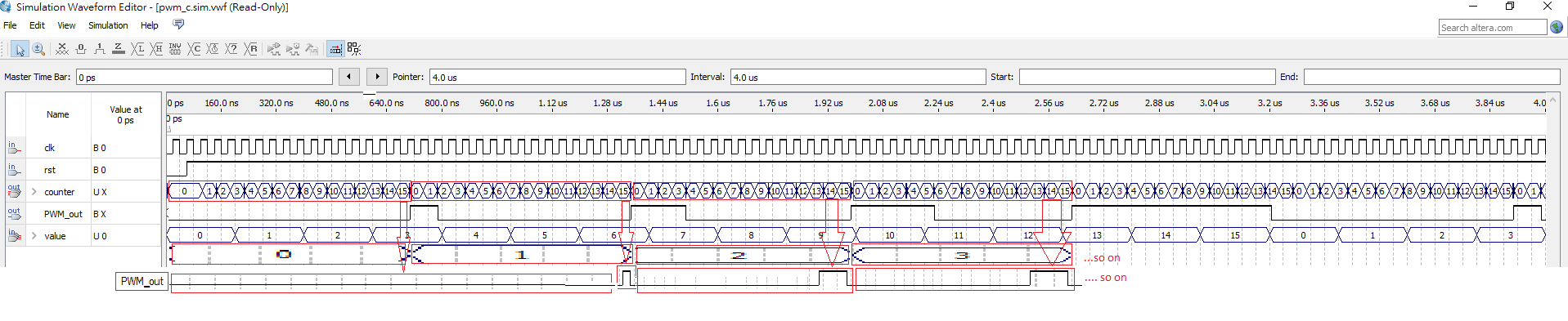
No,The first attachment is what I'm trying to show,that the each value 
should wait for 16 clock cycles before going to the next,like;
value = 0 and PWM_out = 0 and equal to 16 clock cycles then value 
changes to 1,PWM_out= almost 1 clock cycle and equal to 16 clock cycles 
then value changes to 2,PWM_out = 1 clock cycle...etc...

Maybe I'll put it in this way,each `value` is equal to 16 clock cycles.

PWM_out only output at counter==15,and value's 16 clock cycle.

I've redraw the photo...maybe you'll be much more clearly.
But noted,by continue to repeat,I meant that to when value changes to 4 
...PWM_out output equal to 4 clock cycles and value is equal to 16 clock 
cycles. I don't mean 0-1-2-3 to continue repeat but rather the clock 
cycles pattern.

: Edited by User
von Hallo (Guest)


Rate this post
useful
not useful
Your new drawing and my proposal should fit very well

If you would like to have every change of value been "processed", even 
value changes more often than the counter runs over you need an FIFO and 
push data in if value change and pull data out when the counter runs 
over.

von Cm Y. (cmyang)


Rate this post
useful
not useful
Hallo wrote:
> Your new drawing and my proposal should fit very well
>
> If you would like to have every change of value been "processed", even
> value changes more often than the counter runs over you need an FIFO and
> push data in if value change and pull data out when the counter runs
> over.

If your proposal will do what I wanted,
But I only see data in in your proposal,How can I pull it out? I might 
need more hint,'cause I'm really stuck.
1
reg [3:0] value_dly;
2
always_ff@(posedge clk) begin
3
  if(!rst) begin
4
   value_dly<=4'h0;
5
  end else if (counter == 4'hf) begin
6
   value_dly <= value;
7
  end
8
 //Here suppose to have a else begin counter <= counter + 4'h1; end , right? 
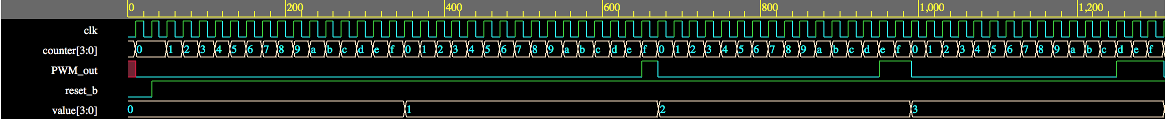
9
 end
10
 
11
  assign PWM_out = (counter > value_dly) ? 1'b1 : 1'b0;

then why mine doesn't work?
1
always@(posedge clk)
2
begin
3
 if(!rst)
4
   begin
5
     counter<=8'd0;
6
   end
7
 else if(counter == 8'd15)
8
   begin
9
     delay<=value;
10
   end
11
 else
12
   begin
13
     counter <= counter + 8'd1;
14
   end
15
end

von Hallo (Guest)


Rate this post
useful
not useful
Okay I think I got it, here with an downward counter:
1
// Code your design here
2
 module pwm_c
3
(
4
   input clk,rst,
5
   input [3:0] value,
6
   output PWM_out,
7
   output reg [3:0]counter
8
);
9
  
10
  
11
  always@(posedge clk)
12
      begin
13
          if(!rst)
14
              counter <= 4'hf;
15
       else
16
              counter <= counter - 4'd1;
17
      end
18
19
   assign PWM_out = (counter < value) ? 1'b1 : 1'b0;
20
21
endmodule
If this is not okay you need to "invert" value:
1
// Code your design here
2
 module pwm_c
3
(
4
   input clk,rst,
5
   input [3:0] value,
6
   output PWM_out,
7
  output reg [3:0]counter
8
);
9
  
10
  always@(posedge clk)
11
      begin
12
          if(!rst)
13
              counter <= 4'h0;
14
       else
15
              counter <= counter + 4'd1;
16
      end
17
   wire [3:0]value_inv;
18
   assign value_inv = 4'hf-value;
19
   assign PWM_out = (counter <= value_inv) ? 1'b0 : 1'b1;
20
21
endmodule

von Hallo (Guest)


Attached files:

Rate this post
useful
not useful
Added simulation screenshot

von Cm Y. (cmyang)


Attached files:

Rate this post
useful
not useful
Hallo wrote:
> Added simulation screenshot

Not Sure What I did wrong...but my simulation result is way different 
from yours...and so much wronger than before...

I tried added your inverted code...

von Hallo (Guest)


Rate this post
useful
not useful
You change value with every clock cycle.
Change of value must be proper specified and I just assumed now that it 
is only allowed to change when the counter runs over.

von Cm Y. (cmyang)


Rate this post
useful
not useful
Hallo wrote:
> You change value with every clock cycle.
> Change of value must be proper specified and I just assumed now that it
> is only allowed to change when the counter runs over.

Ok,I finally understood it,the change of value is what I should set it 
when I simulate it...and 16 clock cycles is what I should count and then 
set the value...

So...It was never the code's problem...

I've got stuck at this for days...THANK YOU SO MUCH.

Please log in before posting. Registration is free and takes only a minute.
Existing account
Do you have a Google/GoogleMail account? No registration required!
Log in with Google account
No account? Register here.