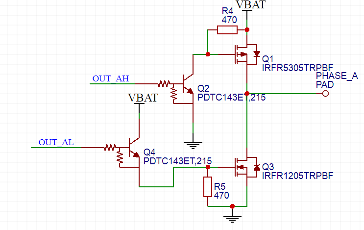
Hello,

I'm currently trying to build a discrete H bridge.
Looking around the internet at existing solutions I came up with the
schematic attached (x2 obviously).
OUT_AH/OUT_AL are powered by 3v3 logic levels.
Is this going to work?
Or did I produce total garbage?
What can I improve?

Sincerely,
Rauchzeichen
Attached files:
-

HBridge.PNG
22 KB
It's late, so I'm not sure, but I see two problems. Are you sure that Q1
doesn't have to be flipped upside down?
But the bigger problem is the the gate drive of Q3. The voltage on the
gate will be OUT_AL minus base-emitter-voltage of Q4. OUT_AL is 3.3 V,
so the gate voltage will be around 2.6 V, which is very close to the
minimum of the threshold voltage range of Q3 (min 2.0 V, max 4.0 V).
That means Q3 will probably be in linear mode, so it will dissipate much
power.
Attached files:
-

HBridge.PNG
24 KB

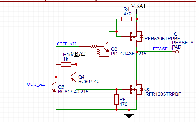
> Are you sure that Q1 doesn't have to be flipped upside down?

You're right, totally missed that.

> The voltage on the gate will be OUT_AL minus base-emitter-voltage of Q4.

Right again, replaced it.

I corrected (at least I hope so) both things.
Mind taking a second look?
Considering both were really obvious I probably should go to bed :)
Attached files:
-

HBridge.PNG
25 KB
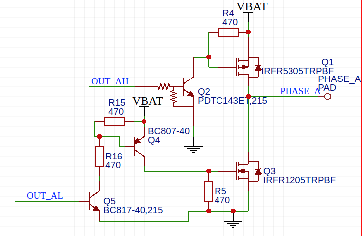
Ignore the last post, I noticed that I screwed it up yet again.
This one should work (I hope).
In principle this does look right (although its only a halfbridge and no
H-Bridge). But as we dont know the height of VBat yet theres still the
possibility of running into limitations of the MOSFets, like maximum
Gate voltage.
Note that charging the highside gate is only done through the 470 Ohm
resistor and if switched on both Q2 and the resistor draw a considerable
current. Thats one of the reasons why a lot of people prefer driving the
gate with Push-Pull drivers, reducing current and improving switching
speed.
Note that Q4 in the last circuit is wrongly inserted - you should
exchange Emitter with Collector.
matztronics wrote:
> Note that Q4 in the last circuit is wrongly inserted - you should
> exchange Emitter with Collector.

... and add a resistor between Q5-C and Q4-B.
Rauchzeichen wrote:
> his one should work (I hope

No, Q4 still wrong.

Why don't you take an existing design, but try to invent the wheel on
your own ?
Attached files:
-

Halfbridge.png
35 KB -

Datasheet.png
72 KB
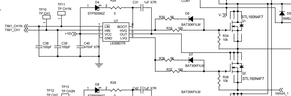
> Why don't you take an existing design, but try to invent the wheel on your own ?

Because otherwise, I'll never find out how the wheel works. However, I
think I'll really use a Driver IC in the end.

> But as we dont know the height of VBat yet

4S => ~16V

Would something like the one in picture 2 be a better option?
Please log in before posting. Registration is free and takes only a minute.
Existing account
Do you have a Google/GoogleMail account? No registration required!
Log in with Google account
Log in with Google account
No account? Register here.