EmbDev.net

Forum: FPGA, VHDL & Verilog UART transmitter


von Hareesh M. (Company: Mindteck) (hareeshp)


Attached files:

Rate this post
useful
not useful
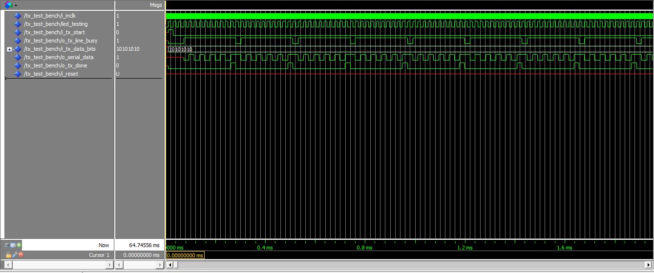
Hi all,
I have written code for UART transmitter with 9600 baud rate. The thing 
is when i simulate the code using modelsim the UART signals are find but 
when i try to use terminal for transmission there is no output.
1
Library ieee;
2
use ieee.std_logic_1164.all;
3
use ieee.numeric_std.all;
4
5
entity uart_tx is
6
7
  generic (
8
          baud_rate_divisor : integer:=520
9
        );
10
  
11
  port (
12
        i_inclk         : in std_logic; --Clock input 50Mhz
13
        i_reset          : in std_logic; --Reset for UART transmission
14
        i_tx_data_bits    : in std_logic_vector(0 to 7); --8 bits of data to be send
15
        i_tx_start      : in std_logic; --
16
        o_tx_done      : out std_logic; --Bit to indicate transmission done
17
        o_tx_line_busy    : out std_logic; --Bit to indicate busy
18
        led_testing      : out std_logic;
19
        test_led        : out std_logic;
20
        o_serial_data    : out std_logic --Data to be send serially
21
        
22
      );
23
      
24
end uart_tx;
25
26
architecture behav of uart_tx is
27
28
  type transmitter_state is(tx_idle,tx_start,tx_data,tx_stop);
29
  signal tx_state:transmitter_state:=tx_idle;
30
31
  signal baud_rate_clk    : std_logic:='0';
32
  signal clk_divider     : integer range 0 to 530:= 0;
33
  signal tx_data_byte    : std_logic_vector(0 to 7);
34
  signal tx_done_bit    : std_logic;
35
  signal out_clk         : std_logic:='0';
36
  signal index_counter    : integer range 0 to 7;
37
38
  
39
  
40
  
41
begin
42
  process(i_reset,i_inclk)
43
  begin
44
    if(i_reset='0')then
45
      clk_divider<=0;
46
    elsif(rising_edge(i_inclk))then
47
      if(clk_divider<baud_rate_divisor)then
48
        clk_divider <= clk_divider+1;        
49
      else
50
        clk_divider <= 0;
51
        baud_rate_clk <= not(baud_rate_clk);
52
      end if;
53
    end if;
54
  end process;
55
  
56
  led_testing <= baud_rate_clk;
57
58
  process(baud_rate_clk)
59
  begin
60
    if(rising_edge(baud_rate_clk))then
61
    
62
      case tx_state is
63
        when tx_idle =>
64
          o_tx_done      <= '0';
65
          o_tx_line_busy <= '0';
66
          index_counter  <=  0;
67
          
68
          if(i_tx_start='0')then
69
            tx_data_byte <= i_tx_data_bits;
70
            tx_state <= tx_start;
71
          else
72
            tx_state <= tx_idle;
73
          end if;
74
          
75
        when tx_start =>
76
          o_tx_line_busy <= '1';
77
          o_serial_data <= '0';
78
          tx_state <= tx_data;
79
          
80
        when tx_data =>
81
          o_serial_data <= tx_data_byte(index_counter);
82
          
83
          if(index_counter<7)then            
84
            index_counter <= index_counter+1;
85
            tx_state <= tx_data;
86
          else
87
            tx_state <= tx_stop;
88
          end if;
89
          
90
        when tx_stop =>
91
          o_serial_data <= '1';
92
          o_tx_done <= '1';
93
          tx_state <= tx_idle;
94
        
95
        when others =>
96
          tx_state <= tx_idle;
97
      end case;
98
    end if;
99
  end process;
100
  
101
  test_led <= i_tx_start;
102
103
end behav;


and the test bench for above code is give
1
LIBRARY ieee  ; 
2
LIBRARY std  ; 
3
USE ieee.NUMERIC_STD.all  ; 
4
USE ieee.std_logic_1164.all  ; 
5
USE ieee.std_logic_textio.all  ; 
6
USE ieee.std_logic_unsigned.all  ; 
7
USE std.textio.all  ; 
8
ENTITY tx_test_bench  IS 
9
  GENERIC (
10
    baud_rate_divisor  : INTEGER   := 520 ); 
11
END ; 
12
 
13
ARCHITECTURE tx_test_bench_arch OF tx_test_bench IS
14
  SIGNAL i_inclk   :  STD_LOGIC  ; 
15
  SIGNAL led_testing : STD_LOGIC;
16
  SIGNAL i_tx_start   :  STD_LOGIC  ; 
17
  SIGNAL o_tx_line_busy   :  STD_LOGIC  ;
18
  SIGNAL i_tx_data_bits   :  STD_LOGIC_VECTOR (0 to 7)  ; 
19
  SIGNAL o_serial_data   :  STD_LOGIC  ; 
20
  SIGNAL o_tx_done   :  STD_LOGIC  ; 
21
  SIGNAL i_reset   :  STD_LOGIC  ; 
22
23
  COMPONENT uart_tx  
24
    GENERIC ( 
25
      baud_rate_divisor  : INTEGER  );  
26
    PORT ( 
27
      i_inclk  : in STD_LOGIC ;
28
    led_testing : out STD_LOGIC;  
29
      i_tx_start  : in STD_LOGIC ; 
30
      o_tx_line_busy  : out STD_LOGIC ; 
31
      i_tx_data_bits  : in STD_LOGIC_VECTOR (0 to 7); 
32
      o_serial_data  : out STD_LOGIC ; 
33
      o_tx_done  : out STD_LOGIC ; 
34
      i_reset  : in STD_LOGIC ); 
35
  END COMPONENT ; 
36
BEGIN
37
  DUT  : uart_tx  
38
    GENERIC MAP ( 
39
      baud_rate_divisor  => baud_rate_divisor   )
40
    PORT MAP ( 
41
      i_tx_start   => i_tx_start  ,
42
      i_inclk   => i_inclk  ,
43
      i_tx_data_bits   => i_tx_data_bits  ,
44
      o_serial_data   => o_serial_data  ,
45
      o_tx_line_busy   => o_tx_line_busy  ,
46
      o_tx_done   => o_tx_done  ,
47
    led_testing => led_testing,
48
      i_reset   => i_reset   ) ; 
49
50
51
52
-- "Clock Pattern" : dutyCycle = 50
53
-- Start Time = 0 ps, End Time = 100 ms, Period = 20 ns
54
  Process
55
  Begin
56
   i_inclk  <= '0'  ;
57
  wait for 10 ns ;
58
   i_inclk  <= '1'  ;
59
  wait for 10 ns ;
60
-- dumped values till 100 ps
61
62
 End Process;
63
64
65
-- "Constant Pattern"
66
-- Start Time = 0 ps, End Time = 10 ps, Period = 0 ps
67
  Process
68
  Begin
69
  wait until rising_edge(led_testing);
70
  i_tx_start  <= '1'  ;
71
  i_tx_data_bits  <= "10101010"  ;
72
  wait until rising_edge(led_testing);
73
  i_tx_start <= '0';
74
  wait until o_tx_done<='1';
75
---- dumped values till 10 ps
76
  wait;
77
 End Process;
78
79
end;


iam also attaching the simulated output

von Lothar M. (Company: Titel) (lkmiller) (Moderator)


Rate this post
useful
not useful
Hareesh M. wrote:
> the test bench for above code is
Drive i_reset with a defined value.

> when i try to use terminal for transmission there is no output.
What terminal? Do you mean when you implement that design on real 
hardware? What does a scope or a logic analyzer show?

This is bad design practice:
1
    baud_rate_clk <= not(baud_rate_clk);
2
:
3
:
4
    if(rising_edge(baud_rate_clk))then
Don't use divided locally distributed clocks in a FPGA. Instead use 
clock enables and only one clock overall the FPGA!

: Edited by Moderator
von Hareesh M. (Company: Mindteck) (hareeshp)


Rate this post
useful
not useful
Lothar M. wrote:
> Hareesh M. wrote:
>> the test bench for above code is
> Drive i_reset with a defined value.

Ok i will do it. Thanks for the comment
>
>> when i try to use terminal for transmission there is no output.
> What terminal? Do you mean when you implement that design on real
> hardware? What does a scope or a logic analyzer show?

I have connected the
1
o_serial_data
 to a gpio in fpga dev board and used a rs232 to usb cable to see the 
output in pc
>
> This is bad design practice:
>
1
>     baud_rate_clk <= not(baud_rate_clk);
2
> :
3
> :
4
>     if(rising_edge(baud_rate_clk))then
5
>
> Don't use divided locally distributed clocks in a FPGA. Instead use
> clock enables and only one clock overall the FPGA!

Thanks for your comment, but if i use a enable signal will i get a clock 
as output. Does 9600bps baud rate generation is fine?

von Lothar M. (Company: Titel) (lkmiller) (Moderator)


Rate this post
useful
not useful
Hareesh M. wrote:
> I have connected the o_serial_data to a gpio in fpga dev board and used
> a rs232 to usb cable to see the output in pc
What cable?
You know, that RS232 has very different signal levels than your FPGA 
output pin?

> Does 9600bps baud rate generation is fine?
Not the way you do it.

> but if i use a enable signal will i get a clock as output.
???
You got lost somewhere. A clock enable is simply implemented in your 
code:
1
  signal baud_tic   : std_logic:='0'; -- the clock enable signal
2
:
3
:
4
  process(i_reset,i_inclk)
5
  begin
6
    if(i_reset='0')then
7
      clk_divider<=0;
8
    elsif(rising_edge(i_inclk))then   -- ONLY ONE AND THE SAME CLOCK in the whole design!
9
      if(clk_divider<1234)then        -- adapt this value
10
        clk_divider <= clk_divider+1; 
11
        baud_tic <= '0';
12
      else
13
        clk_divider <= 0;
14
        baud_tic <= '1';              -- clock enable active for one clock cycle
15
      end if;
16
    end if;
17
  end process;
18
  
19
  led_testing <= baud_rate_clk;
20
21
  process(i_inclk)
22
  begin
23
    if(rising_edge(i_inclk))then      -- ONLY ONE AND THE SAME CLOCK in the whole design!
24
    if baud_tic='1' then              -- this is the clock enable
25
      case tx_state is
26
        when tx_idle =>
27
          o_tx_done      <= '0';
28
          o_tx_line_busy <= '0';
29
          index_counter  <=  0;
30
:
31
:

: Edited by Moderator
von Hareesh M. (Company: Mindteck) (hareeshp)


Rate this post
useful
not useful
Lothar M. wrote:
> Hareesh M. wrote:
>> I have connected the o_serial_data to a gpio in fpga dev board and used
>> a rs232 to usb cable to see the output in pc
> What cable?
> You know, that RS232 has very different signal levels than your FPGA
> output pin?

The gpio which i have connected in fpga dev board is of 3.3V and the 
rs232 voltage level range between  +3 to +15 volts or the range −3 to 
−15

von Lothar M. (Company: Titel) (lkmiller) (Moderator)


Rate this post
useful
not useful
Hareesh M. wrote:
> The gpio which i have connected in fpga dev board is of 3.3V and the
> rs232 voltage level range between  +3 to +15 volts or the range −3 to −15
And does this fit togeher? And does the polarity of a '1' and a '0' fit 
together?

A hint: look for a levelshifter like MAX3232

Or better: look for a "ttl 3V RS232-USB adapter"
https://www.google.com/search?q=ttl+3V+RS232-USB+adapter

: Edited by Moderator
von Hareesh M. (Company: Mindteck) (hareeshp)


Attached files:

Rate this post
useful
not useful
Lothar M. wrote:
> Hareesh M. wrote:
>> The gpio which i have connected in fpga dev board is of 3.3V and the
>> rs232 voltage level range between  +3 to +15 volts or the range −3 to −15
> And does this fit togeher? And does the polarity of a '1' and a '0' fit
> together?
>
> A hint: look for a levelshifter like MAX3232
>
> Or better: look for a "ttl 3V RS232-USB adapter"
> https://www.google.com/search?q=ttl+3V+RS232-USB+adapter

I have attached the cable picture.And i tried to probe the signal in CRO 
also, but nothing is coming.

von Lothar M. (Company: Titel) (lkmiller) (Moderator)


Rate this post
useful
not useful
Hareesh M. wrote:
> I have attached the cable picture.
Ok, a 3V-RS232 levelshifter is necessary with that.

von Lothar M. (Company: Titel) (lkmiller) (Moderator)


Rate this post
useful
not useful
Hareesh M. wrote:
> i tried to probe the signal in CRO also
CRO? Whtas the long meaning of that TLA?

von Hareesh M. (Company: Mindteck) (hareeshp)


Rate this post
useful
not useful
Lothar M. wrote:
> Hareesh M. wrote:
>> i tried to probe the signal in CRO also
> CRO? Whtas the long meaning of that TLA?

I meant the oscilloscope.

von Lothar M. (Company: Titel) (lkmiller) (Moderator)


Rate this post
useful
not useful
Hareesh M. wrote:
> but nothing is coming.
So you must dig into that: why is there nothing?
Do you activate the i_tx_start signal in your hardware?

Can you see anything on your led_testing output?

von Hareesh M. (Company: Mindteck) (hareeshp)


Rate this post
useful
not useful
Lothar M. wrote:
> Hareesh M. wrote:
>> but nothing is coming.
> So you must dig into that: why is there nothing?
> Do you activate the i_tx_start signal in your hardware?
>
> Can you see anything on your led_testing output?

i have connected the signal i_tx_start to a push button.

clock out is coming at led_testing.

von Lothar M. (Company: Titel) (lkmiller) (Moderator)


Rate this post
useful
not useful
Hareesh M. wrote:
> i have connected the signal i_tx_start to a push button.
Just a simple button? Without a additional pullup or a pulldown? And 
what signal level do you measure at that input?

What happens when you change your code in a way that the transmission 
always starts on its own in an endless loop? For debugging I would add 
thre additional LED and set one of them in each state of that FSM to 
see, where the thing stucks.

: Edited by Moderator
von Hareesh M. (Company: Mindteck) (hareeshp)


Rate this post
useful
not useful
Lothar M. wrote:
> Hareesh M. wrote:
>> i have connected the signal i_tx_start to a push button.
> Just a simple button? Without a additional pullup or a pulldown? And
> what signal level do you measure at that input?

A button with a pull down.

>
> What happens when you change your code in a way that the transmission
> always starts on its own in an endless loop? For debugging I would add
> thre additional LED and set one of them in each state of that FSM to
> see, where the thing stucks.

Actually i have tried this, and the led is set when code go into each 
state.

von Hareesh M. (Company: Mindteck) (hareeshp)


Rate this post
useful
not useful
Lothar M. wrote:
> Hareesh M. wrote:
>> I have connected the o_serial_data to a gpio in fpga dev board and used
>> a rs232 to usb cable to see the output in pc
> What cable?
> You know, that RS232 has very different signal levels than your FPGA
> output pin?
>
>> Does 9600bps baud rate generation is fine?
> Not the way you do it.

Could you please suggest the changes??

von Lothar M. (Company: Titel) (lkmiller) (Moderator)


Rate this post
useful
not useful
Hareesh M. wrote:
> Could you please suggest the changes??
I did. With the "clock enable" the design is whats called "synchonous".

Hareesh M. wrote:
> Actually i have tried this, and the led is set when code go into each
> state.
So you see on the LED your design stepping throughout the 4 states? But 
you don't see any changes on o_serial_data although its set in 
tx_stop and it reset in tx_start?

von hareesh (Guest)


Rate this post
useful
not useful
Lothar M. wrote:
> Hareesh M. wrote:
>> Could you please suggest the changes??
> I did. With the "clock enable" the design is whats called "synchonous".
>
> Hareesh M. wrote:
>> Actually i have tried this, and the led is set when code go into each
>> state.
> So you see on the LED your design stepping throughout the 4 states? But
> you don't see any changes on o_serial_data although its set in
> tx_stop and it reset in tx_start?

Hi  Lothar ,
The signals are coming in o_serial_data. the issue was with the i_reset 
signal.
Thanks for your valuable comments. Now i need to use a usb to serial 
cable to see the signals in pc.

Please log in before posting. Registration is free and takes only a minute.
Existing account
Do you have a Google/GoogleMail account? No registration required!
Log in with Google account
No account? Register here.