EmbDev.net

Forum: FPGA, VHDL & Verilog Designated Number Counter and Cycle counter 2 Digit


von Jason W. (Company: n/a) (grauado)


Attached files:

Rate this post
useful
not useful
Greetings.
Not long ago I've written this code shown down below for a BCD timer,
showing on 4 digit Seven Segment Display.
But now,I would like to change it to the design shown in the attachment 
file,
how can I do that?

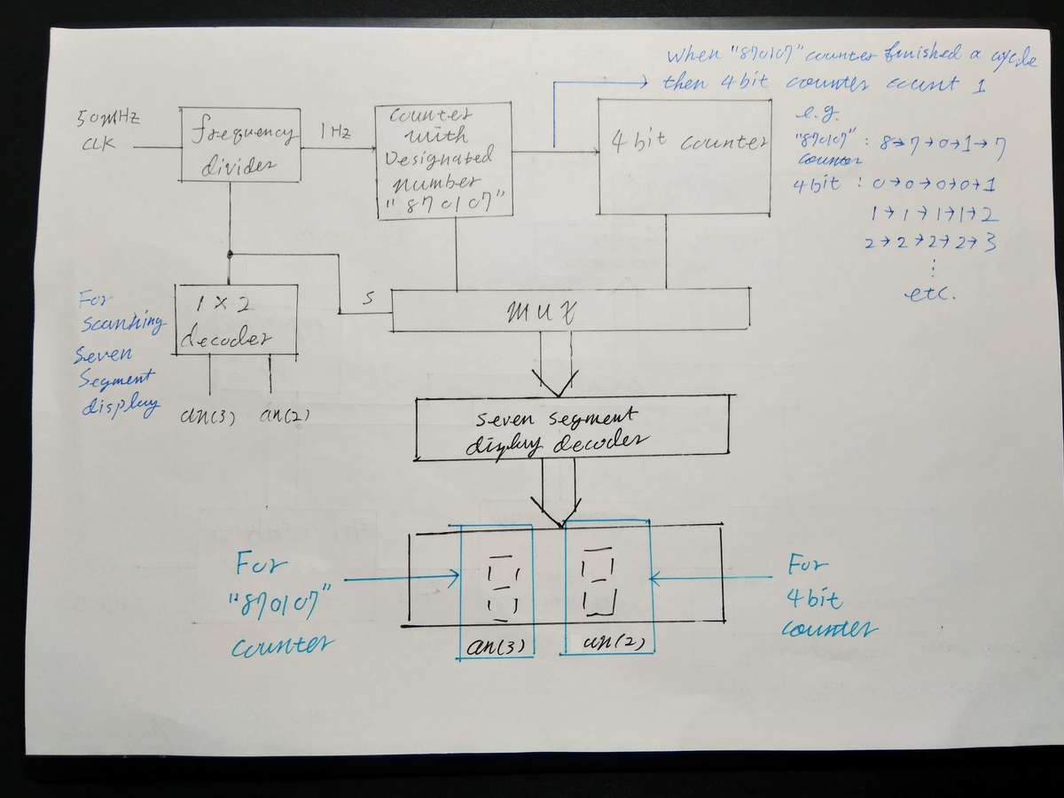
In case there's any confusion in attached sketch,
My intention is to modify this code to a design
that has two counters,first counting designated number "870107",
second counter counts when first finished a "870107" cycle,
e.g. First counter : 8>7>0>1>0>7
    Second counter : 0>0>0>0>0>1
                     1>1>1>1>1>2
                     2>2>2>2>2>3
                     ...and so on...
and only using 2 of 4 seven segment display on the board.

and frequency divider divide my spartan 3E board's 50MHZ to 1HZ.
    decoder for scanning/refresh seven segment display
    Multiplexer to decide which Seven segment display to activate

Sincerely Appreciate to any assists.
1
 library IEEE;
2
use IEEE.STD_LOGIC_1164.ALL;
3
use IEEE.std_logic_unsigned.all;
4
use IEEE.NUMERIC_STD.ALL;
5
6
7
entity seven_segment_display is
8
    Port ( clk : in  STD_LOGIC;
9
           reset : in  STD_LOGIC;
10
        pause : in  STD_LOGIC;
11
           Anode_Activate : out  STD_LOGIC_VECTOR (3 downto 0);
12
           LED_out : out  STD_LOGIC_VECTOR (6 downto 0));
13
end seven_segment_display;
14
15
architecture Behavioral of seven_segment_display is
16
signal one_second_counter: STD_LOGIC_VECTOR (18 downto 0);
17
signal one_second_enable: std_logic;
18
signal displayed_number: STD_LOGIC_VECTOR (15 downto 0);
19
signal LED_BCD: STD_LOGIC_VECTOR (3 downto 0);
20
signal refresh_counter: STD_LOGIC_VECTOR (10 downto 0);
21
signal LED_activating_counter: std_logic_vector(1 downto 0);
22
begin
23
process(LED_BCD)
24
begin
25
    case LED_BCD is
26
    when "0000" => LED_out <= "0000001"; -- "0"     
27
    when "0001" => LED_out <= "1001111"; -- "1" 
28
    when "0010" => LED_out <= "0010010"; -- "2" 
29
    when "0011" => LED_out <= "0000110"; -- "3" 
30
    when "0100" => LED_out <= "1001100"; -- "4" 
31
    when "0101" => LED_out <= "0100100"; -- "5" 
32
    when "0110" => LED_out <= "0100000"; -- "6" 
33
    when "0111" => LED_out <= "0001111"; -- "7" 
34
    when "1000" => LED_out <= "0000000"; -- "8"     
35
    when "1001" => LED_out <= "0000100"; -- "9" 
36
    when "1010" => LED_out <= "0000010"; -- a
37
    when "1011" => LED_out <= "1100000"; -- b
38
    when "1100" => LED_out <= "0110001"; -- C
39
    when "1101" => LED_out <= "1000010"; -- d
40
    when "1110" => LED_out <= "0110000"; -- E
41
    when "1111" => LED_out <= "0111000"; -- F
42
    end case;
43
end process;
44
process(clk,reset)
45
begin 
46
    if(reset='1') then
47
        refresh_counter <= (others => '0');
48
    elsif(rising_edge(clk)) then
49
        refresh_counter <= refresh_counter + 1;
50
    end if;
51
end process;
52
 LED_activating_counter <= refresh_counter(9 downto 8);
53
process(LED_activating_counter)
54
begin
55
    case LED_activating_counter is
56
    when "00" =>
57
        Anode_Activate <= "0111"; 
58
        LED_BCD <= displayed_number(15 downto 12);
59
    when "01" =>
60
        Anode_Activate <= "1011"; 
61
        LED_BCD <= displayed_number(11 downto 8);
62
    when "10" =>
63
        Anode_Activate <= "1101"; 
64
        LED_BCD <= displayed_number(7 downto 4);
65
    when "11" =>
66
        Anode_Activate <= "1110"; 
67
        LED_BCD <= displayed_number(3 downto 0);
68
   when others => Anode_Activate <= "0111";
69
    end case;
70
end process;
71
process(clk, reset)
72
begin
73
        if(reset='1') then
74
            one_second_counter <= (others => '0');
75
        elsif(rising_edge(clk)) then
76
            if(one_second_counter>=x"7FFFF") then
77
                one_second_counter <= (others => '0');
78
            else
79
                one_second_counter <= one_second_counter + "0000001";
80
            end if;
81
        end if;
82
end process;
83
one_second_enable <= '1' when one_second_counter=x"7FFFF" else '0';
84
process(clk, reset)
85
begin
86
        if(reset='1') then
87
            displayed_number <= (others => '0');
88
          elsif (pause = '1') then
89
            displayed_number <= displayed_number;
90
            elsif(rising_edge(clk)) then
91
              if(one_second_enable='1') then
92
                displayed_number <= displayed_number + x"0001";
93
                end if;
94
        end if;
95
end process;
96
97
end Behavioral;

von Lothar M. (Company: Titel) (lkmiller) (Moderator)


Rate this post
useful
not useful
Jason W. wrote:
> use IEEE.std_logic_unsigned.all;
> use IEEE.NUMERIC_STD.ALL;
One hint in advance: NEVER EVER use both of the math libs. It will bring 
strange effects due to double type definitions now and then. Use the 
numeric_std solely. It has all you need!

Now this:
1
             if(one_second_counter>=x"7FFFF") then
2
                 one_second_counter <= (others => '0');
3
             else
4
                 one_second_counter <= one_second_counter + "0000001";
5
             end if;
Do you really have a oscillator with 1048576 Hz?
If not, then why not counting in a manner even humans are able to read?
1
signal one_second_counter: integer range 0 to 999999 := 0;
2
:
3
:
4
             if(one_second_counter=999999) then
5
                 one_second_counter <= 0;
6
             else
7
                 one_second_counter <= one_second_counter + 1;
8
             end if;

Jason W. wrote:
1
 e.g. First counter : 8>7>0>1>0>7
2
     Second counter : 0>0>0>0>0>1
3
                      1>1>1>1>1>2
4
                      2>2>2>2>2>3
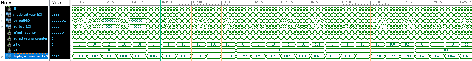
So far I see those both together count like this:
08, 07, 00, 01, 00, 17, 18, 17, 10, 11, 10, 27, 28, 27, 20, 21, 20, 37, 
38 and so on. Ist this assumption correct?

Then first i would turn the sequence a little and start with the "second 
value":
1
low digit:  7 8 7 0 1 0
2
high digit: x 0 0 0 0 0
3
            1 1 1 1 1 1
4
            2 2 2 2 2 2
5
            3 3 3 3 3 3
Now the pattern looks more like a simple counter...

Having done that, you see that you can't count on the numbers directly, 
because some numbers appear two times and you can't step forward the 
counting FSM in 2 different ways. So simply do it with 2 counters: one 
counting from 0 to 5 for the 787010 sequence and the other for the 
straightforward high-digit of the counter.
And then select the low-digit value according to the counting index of 
the low counter.
1
library IEEE;
2
use IEEE.STD_LOGIC_1164.ALL;
3
use IEEE.NUMERIC_STD.ALL;
4
:
5
:
6
signal cntlo : integer range 0 to 5 := 1; -- start with display 80!
7
signal cnthi : integer range 0 to 9 := 0;
8
signal one_second_counter: integer range 0 to 999999 := 0;
9
:
10
:
11
process begin -- the prescaler and counter
12
   wait until rising_edge(clk);
13
   if one_second_counter<999999 then
14
      one_second_counter <= one_second_counter + 1;
15
   else
16
      one_second_counter <= 0;
17
      if cntlo<5 then
18
         cntlo <= cntlo+1;
19
      else
20
         cntlo <= 0;
21
         if cnthi<9 then
22
            cnthi <= cnthi+1;
23
         else
24
            cnthi <= 0;
25
            cntlo <= 0;
26
         end if;
27
      end if;
28
   end if;
29
end process;
30
:
31
:
32
displayed_number(15 downto 8) <= (others => '0');
33
displayed_number(7 downto 4) <= std_logic_vector(to_unsigned(cnthi, 4));
34
displayed_number(3 downto 0) <= x"7" when cntlo = 0 else
35
                                x"8" when cntlo = 1 else
36
                                x"7" when cntlo = 2 else
37
                                x"0" when cntlo = 3 else
38
                                x"1" when cntlo = 4 else
39
                                x"0" when cntlo = 5;
40
:
41
:
Got the trick?

: Edited by Moderator
von Jason W. (Company: n/a) (grauado)


Rate this post
useful
not useful
>Lothar M. wrote
1
library IEEE;
2
 use IEEE.STD_LOGIC_1164.ALL;
3
 use IEEE.NUMERIC_STD.ALL;
4
 :
5
 :
6
 signal cntlo : integer range 0 to 5 := 1; -- start with display 80!
7
 signal cnthi : integer range 0 to 9 := 0;
8
 signal one_second_counter: integer range 0 to 999999 := 0;
9
 :
10
 :
11
 process begin -- the prescaler and counter
12
    wait until rising_edge(clk);
13
    if one_second_counter<999999 then
14
       one_second_counter <= one_second_counter + 1;
15
    else
16
       one_second_counter <= 0;
17
       if cntlo<5 then
18
          cntlo <= cntlo+1;
19
       else
20
          cntlo <= 0;
21
          if cnthi<9 then
22
             cnthi <= cnthi+1;
23
          else
24
             cnthi <= 0;
25
             cntlo <= 0;
26
          end if;
27
       end if;
28
    end if;
29
 end process;
30
 :
31
 :
32
 displayed_number(15 downto 8) <= (others => '0');
33
 displayed_number(7 downto 4) <= std_logic_vector(to_unsigned(cnthi, 4));
34
 displayed_number(3 downto 0) <= x"7" when cntlo = 0 else
35
                                 x"8" when cntlo = 1 else
36
                                 x"7" when cntlo = 2 else
37
                                 x"0" when cntlo = 3 else
38
                                 x"1" when cntlo = 4 else
39
                                 x"0" when cntlo = 5;
40
 :
41
 :

I'm not quite get it,If the code changed it into this,then where does my 
original code's MUX and Case statement fit in?Ditch the Case statements?
And how do I implement the actual LED_out(Seven Segment Display) output?
Your code is indeed human friendly,but it's quite too simple to me to 
understand.

von Lothar M. (Company: Titel) (lkmiller) (Moderator)


Rate this post
useful
not useful
Jason W. wrote:
> And how do I implement the actual LED_out(Seven Segment Display) output?
They do the same as now. I did not lay my hand on the display part. I 
only changed the counter part. the interface to your part of the design 
is the vector "displayed_number". Just think about it for some minutes 
or a few hours...

BTW: the sensitivity list in your
> process(LED_activating_counter)
is incomplete! The signal displayed_number is missing. Therfore the 
simulation will not match the reality. The synthesizer will report some 
kind of warning or info about that...

von Jason W. (Company: n/a) (grauado)


Rate this post
useful
not useful
Lothar M. wrote:
> Jason W. wrote:
>> And how do I implement the actual LED_out(Seven Segment Display) output?
> They do the same as now. I did not lay my hand on the display part. I
> only changed the counter part. the interface to your part of the design
> is the vector "displayed_number". Just think about it for some minutes
> or a few hours...
>
> BTW: the sensitivity list in your
>> process(LED_activating_counter)
> is incomplete! The signal displayed_number is missing. Therfore the
> simulation will not match the reality. The synthesizer will report some
> kind of warning or info about that...

So after changed codes with your suggestion.I tried to implement them 
together and not sure where I've done wrong..
It's closed to the result but not quite...
1
library IEEE;
2
use IEEE.STD_LOGIC_1164.ALL;
3
use IEEE.std_logic_unsigned.all;
4
use IEEE.NUMERIC_STD.ALL;
5
6
7
entity seven_segment_display is
8
    Port ( clk : in  STD_LOGIC;
9
           reset : in  STD_LOGIC;
10
           Anode_Activate : out  STD_LOGIC_VECTOR (3 downto 0);
11
           LED_out : out  STD_LOGIC_VECTOR (6 downto 0));
12
end seven_segment_display;
13
14
architecture Behavioral of seven_segment_display is
15
signal displayed_number: STD_LOGIC_VECTOR (15 downto 0);
16
signal LED_BCD: STD_LOGIC_VECTOR (3 downto 0);
17
signal refresh_counter: STD_LOGIC_VECTOR (5 downto 0);
18
signal LED_activating_counter: std_logic_vector(1 downto 0);
19
signal cntlo : integer range 0 to 5 := 1; -- start with display 80!
20
signal cnthi : integer range 0 to 9 := 0;
21
signal one_second_counter: integer range 0 to 33554431 := 0;
22
23
begin
24
process(LED_BCD)
25
begin
26
    case LED_BCD is
27
    when "0000" => LED_out <= "0001111"; -- "7" 
28
    when "0001" => LED_out <= "0000000"; -- "8"
29
   when "0010" => LED_out <= "0001111"; -- "7"
30
   when "0011" => LED_out <= "0000001"; -- "0"  
31
   when "0100" => LED_out <= "1001111"; -- "1"
32
    when "0101" => LED_out <= "0000001"; -- "0"
33
   when others => LED_out <= "0001111";
34
    end case;
35
end process;
36
process(clk,reset)
37
begin 
38
    if(reset='1') then
39
        refresh_counter <= (others => '0');
40
    elsif(rising_edge(clk)) then
41
        refresh_counter <= refresh_counter + 1;
42
    end if;
43
end process;
44
 LED_activating_counter <= refresh_counter(5 downto 4);
45
process(LED_activating_counter)     -- MUX Not working , Warnings showed that :
46
                          --'One or more signals are missing in the process sensitivity list. 
47
                          --To enable synthesis of FPGA/CPLD hardware, XST will assume that all necessary signals are present in the sensitivity list. 
48
                          --Please note that the result of the synthesis may differ from the initial design specification. The missing signals are: 'displayed_number'
49
begin
50
    case LED_activating_counter is      
51
    when "00" =>
52
        Anode_Activate <= "0101"; 
53
        LED_BCD <= displayed_number(7 downto 4);
54
    when "01" =>
55
        Anode_Activate <= "1010"; 
56
        LED_BCD <= displayed_number(3 downto 0);        
57
   when others => Anode_Activate <= "0101";
58
    end case;
59
end process;
60
61
process begin -- the prescaler and counter
62
   wait until rising_edge(clk);
63
   if one_second_counter < 33554431 then
64
      one_second_counter <= one_second_counter + 1;
65
   else
66
      one_second_counter <= 0;
67
      if cntlo<5 then
68
         cntlo <= cntlo+1;
69
      else
70
         cntlo <= 0;
71
         if cnthi<9 then
72
            cnthi <= cnthi+1;
73
         else
74
            cnthi <= 0;
75
            cntlo <= 0;
76
         end if;
77
      end if;
78
   end if;
79
end process;
80
81
displayed_number(15 downto 8) <= (others => '0');
82
displayed_number(7 downto 4) <= std_logic_vector(to_unsigned(cnthi, 4));
83
displayed_number(3 downto 0) <= x"7" when cntlo = 0 else
84
                                x"8" when cntlo = 1 else
85
                                x"7" when cntlo = 2 else
86
                                x"0" when cntlo = 3 else
87
                                x"1" when cntlo = 4 else
88
                                x"0" when cntlo = 5;
89
end Behavioral;
And a lot of Warnings Messages...
WARNING:Xst:646 - Signal <displayed_number<15:8>> is assigned but never 
used. This unconnected signal will be trimmed during the optimization 
process.
WARNING:Xst:737 - Found 4-bit latch for signal <LED_BCD>. Latches may be 
generated from incomplete case or if statements. We do not recommend the 
use of latches in FPGA/CPLD designs, as they may lead to timing 
problems.
WARNING:Xst:737 - Found 1-bit latch for signal <displayed_number_0>. 
Latches may be generated from incomplete case or if statements. We do 
not recommend the use of latches in FPGA/CPLD designs, as they may lead 
to timing problems.
WARNING:Xst:737 - Found 1-bit latch for signal <displayed_number_1>. 
Latches may be generated from incomplete case or if statements. We do 
not recommend the use of latches in FPGA/CPLD designs, as they may lead 
to timing problems.
WARNING:Xst:737 - Found 1-bit latch for signal <displayed_number_3>. 
Latches may be generated from incomplete case or if statements. We do 
not recommend the use of latches in FPGA/CPLD designs, as they may lead 
to timing problems.
WARNING:PhysDesignRules:372 - Gated clock. Clock net 
displayed_number_0_or0000
   is sourced by a combinatorial pin. This is not good design practice. 
Use the
   CE pin to control the loading of data into the flip-flop.
WARNING:Route:455 - CLK Net:displayed_number_0_or0000 may have excessive 
skew because
WARNING:Route:455 - CLK Net:refresh_counter<5> may have excessive skew 
because
WARNING:PhysDesignRules:372 - Gated clock. Clock net 
displayed_number_0_or0000
   is sourced by a combinatorial pin. This is not good design practice. 
Use the
   CE pin to control the loading of data into the flip-flop.

von Lothar M. (Company: Titel) (lkmiller) (Moderator)


Rate this post
useful
not useful
Jason W. wrote:
> I tried to implement them together and not sure where I've done wrong..
> And a lot of Warnings Messages...
Those messages may help you.

> The missing signals are: 'displayed_number'
As I already said. So add this signal.

> Signal <displayed_number<15:8>> is assigned but never used.
Thats correct. You do not use them, so they are hard wired to 0.

> if one_second_counter < 33554431 then
What the heck? What crystal do you use? Is it really a 33.554432 MHz 
oscillator? Or did you find that number by dicing?

> Found 4-bit latch for signal <LED_BCD>. Latches may be generated from
> incomplete case or if statements.
You wrote it in that way...

> We do not recommend the use of latches
> in FPGA/CPLD designs, as they may lead to timing problems.
"Do not recommend" is nice. You never ever MUST have latches unless you 
really need one and you know deeply what you are doing.

In your design all of those latches are serious design flaws due to

> use IEEE.std_logic_unsigned.all;
> use IEEE.NUMERIC_STD.ALL;
What did I say about this pair?

Jason W. wrote:
1
 begin
2
 process(LED_BCD)
3
 begin
4
     case LED_BCD is
5
    when "0000" => LED_out <= "0001111"; -- "7" 
6
    when "0001" => LED_out <= "0000000"; -- "8"
7
   when "0010" => LED_out <= "0001111"; -- "7"
8
   when "0011" => LED_out <= "0000001"; -- "0"  
9
   when "0100" => LED_out <= "1001111"; -- "1"
10
    when "0101" => LED_out <= "0000001"; -- "0"
11
   when others => LED_out <= "0001111";
Why did you do that? I said: do not change any more than that counter. 
With these modification you cannot display other number than 0,1,7 and 
8, you know?
I already did the mapping for the counter to the number in the last few 
lines of your code.
As I already said: THINK ABOUT THE POSTED CODE.
And when you understand it, then change it.

von Lothar M. (Company: Titel) (lkmiller) (Moderator)


Attached files:

Rate this post
useful
not useful
Ok, I did a litte finger twist in the lunch break. For me simulation 
looks fine, and there are no warnings during synthesizing...

von Jason W. (Company: n/a) (grauado)


Rate this post
useful
not useful
Lothar M. wrote:
> Ok, I did a litte finger twist in the lunch break. For me simulation
> looks fine, and there are no warnings during synthesizing...
1
 signal refresh_counter: integer range 0 to 63 := 0;
why 0 to 63? what's this controlling?
after your twists,can you tell me which part controls the displaying of 
Seven Segment Display,'cause I would like to add pause and reset bottom.

von Jason W. (Company: n/a) (grauado)


Rate this post
useful
not useful
Although the code's right,still doesn't display right at the 
board...ummm...thinking it.

von Lothar M. (Company: Titel) (lkmiller) (Moderator)


Rate this post
useful
not useful
Jason W. wrote:
> why 0 to 63? what's this controlling?
Just a random number. It's controlling the display MUX frequency. 
Almost similar to your even so random counting vector 5 downto 0 (which 
was 10 downto 0 in the first code).

A hint: analyze what's happening and adjust those counters top values to 
your specific FPGA clock and to your desired multiplex frequency.

> cause I would like to add pause and reset bottom.
Obviously a little work left over...

Jason W. wrote:
> still doesn't display right at the board...
What instead?

> ummm...thinking it.
Good idea ?
A hint here: it may be decades too fast...

: Edited by Moderator
von Jason W. (Company: n/a) (grauado)


Rate this post
useful
not useful
Lothar M. wrote:
> What instead?
The codes seemed fine,but on the board the seven segment display is 
continuously light up whenever it counts,like it counts to 7 but still 
light up looks like 8 or only 0 lighting up,I've checked pins for seven 
segment,and they weren't wrong...

I can see a bit of result,but it's not quite what I described...

it's counting like 80>71>02>13>04>75>...etc.
but what I wanted is:
80>70>00>10>00>70>81>71>01>11>01>71>82>72>02>12>72>...etc

: Edited by User
von Lothar M. (Company: Titel) (lkmiller) (Moderator)


Rate this post
useful
not useful
Jason W. wrote:
> light up looks like 8 or only 0 lighting up
Your eye is much too slow to get up with the mux and counting speed. The 
counters run so fast, that you see all of the numbers at once.

> I've checked pins for seven segment,and they weren't wrong...
You're digging at the wrong part of the design! I said: check the 
counters top values and adapt it to YOUR specific needs. Is that sooooo 
difficult to understand?
You have a "one_second_counter" that counts up to 33554431 and then 
forwards the digit values. So lets assume you have a oscillator 
frequency and therfore a FPGA clock of somewhat in the 33MHz range.
In my design I only count to 999 to get a faster simulation. And now the 
question of questions: what is the difference between 1000 and 33554432?
You are rigt: the second is 33554 times greater than the first, and so 
my "one_second_counter" will advance 33554 times faster than yours. Got 
it?

Jason W. wrote:
> I can see a bit of result,but it's not quite what I described...
> it's counting like 80>71>02>13>04>75>...etc.
With what code?

> but what I wanted is:
> 80>70>00>10>00>70>81>71>01>11>01>71>82>72>02>12>72>...etc
Huh, then you have to twist those two digits. Because I assumed that the 
faster countig value is the rightmost digit.

: Edited by Moderator
von Jason W. (Company: n/a) (grauado)


Rate this post
useful
not useful
Lothar M. wrote:
>>Jason W. wrote
>> but what I wanted is:
>> 80>70>00>10>00>70>81>71>01>11>01>71>82>72>02>12>72>...etc
> Huh, then you have to twist those two digits. Because I assumed that the
> faster countig value is the rightmost digit.

So I'm guessing that what I need to twist is in this section?
1
signal cntlo : integer range 0 to 5 := 1; -- start with display 80!
2
signal cnthi : integer range 0 to 9 := 0;
3
4
process begin -- the prescaler and counter
5
   wait until rising_edge(clk);
6
   if one_second_counter < 9999998 then
7
      one_second_counter <= one_second_counter + 1;
8
   else
9
      one_second_counter <= 0;
10
      if cntlo<5 then
11
         cntlo <= cntlo+1;
12
      else
13
         cntlo <= 0;
14
         if cnthi<9 then
15
            cnthi <= cnthi+1;
16
         else
17
            cnthi <= 0;
18
            cntlo <= 0;
19
         end if;
20
      end if;
21
   end if;
22
end process;
23
24
displayed_number(15 downto 8) <= (others => '0');
25
displayed_number(7 downto 4) <= std_logic_vector(to_unsigned(cnthi, 4));
26
displayed_number(3 downto 0) <= x"7" when cntlo = 0 else
27
                                x"8" when cntlo = 1 else
28
                                x"7" when cntlo = 2 else
29
                                x"0" when cntlo = 3 else
30
                                x"1" when cntlo = 4 else
31
                                x"0";

how do I keep one digit at one seven seg's?
like "787010" use one seven seg's and other counter for one seven seg's?
something to do with here? e.g. [8,0] [7,0] [0,0] [1,0] [7,0]
1
process(LED_activating_counter, displayed_number)
2
begin
3
    case LED_activating_counter is
4
    when 0 =>
5
        Anode_Activate <= "1001"; 
6
        LED_BCD <= displayed_number(15 downto 12);
7
    when 1 =>
8
        Anode_Activate <= "1001"; 
9
        LED_BCD <= displayed_number(11 downto 8);
10
    when 2 =>
11
        Anode_Activate <= "1001"; 
12
        LED_BCD <= displayed_number(7 downto 4);
13
    when 3 =>
14
        Anode_Activate <= "1001"; 
15
        LED_BCD <= displayed_number(3 downto 0);
16
    end case;
17
end process;

von Lothar M. (Company: Titel) (lkmiller) (Moderator)


Rate this post
useful
not useful
Jason W. wrote:
1
        Anode_Activate <= "1001"; 
2
        :
3
        Anode_Activate <= "1001"; 
4
        :
5
        Anode_Activate <= "1001"; 
6
        :
7
        Anode_Activate <= "1001";
Try to understand what "Anode_Activate" does. Then you will easily find 
out, why this is not working as you want to. At the moment it looks to 
me you are digging around in that design absolutely not knowing what and 
where, and so its a really laboriuos job to get you an the track...

> if one_second_counter < 9999998 then
This is almost fine for a 10MHz clock. But up to now its completely 
secret, what clock you really have, you know?

Please log in before posting. Registration is free and takes only a minute.
Existing account
Do you have a Google/GoogleMail account? No registration required!
Log in with Google account
No account? Register here.