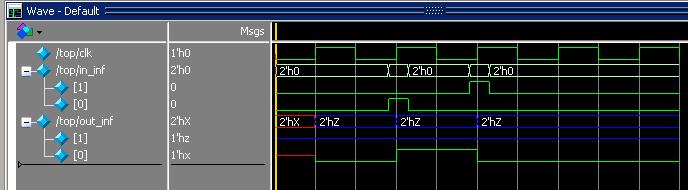
i try to simulate [1:0]flip-flop in ModelSim and i see one normal
signal(out_inf[0]) and one blue signal(out_inf[1]). What is it?
Attached files:
-

mod_flipflop.JPG
26 KB
testbench tdff.v
1 | module top; |
2 | reg clk; |
3 | reg [1:0] in_inf; |
4 | wire [1:0] out_inf; |
5 | dff D1 (clk, in_inf, out_inf); |
6 | |
7 | initial // Clock generator |
8 | begin |
9 | clk = 0; |
10 | forever #10 clk = !clk; |
11 | end |
12 | |
13 | initial //in_inf[0] |
14 | begin |
15 | in_inf[0] = 0; |
16 | #28 in_inf[0] = 1; |
17 | #5 in_inf[0] = 0; |
18 | end |
19 | initial //in_inf[1] |
20 | begin |
21 | in_inf[1] = 0; |
22 | #48 in_inf[1] = 1; |
23 | #5 in_inf[1] = 0; |
24 | end |
25 | endmodule |
whats the difference between in_inf[0] and in_inf[1]
Dima P. wrote:
> whats the difference between in_inf[0] and in_inf[1]
Thats remains the question.
What you posted is the test bench. That obvoiusly works properly...
thanks, but why out_inf[1] is hi-z? how do i see normal(not blue) signal
as out_inf[1]?
Dima P. wrote:
> thanks, but why out_inf[1] is hi-z?
Thats in the up to now secret code of the flipflop itself. What you
posted generates the clk and the in_inf signals. And they are fine.
Dima P. wrote:
> And whats mean red signal 1'hx out_inf[0]?
Behind the h is the value of the signal, in this case X. If you look up
the definition of std_(u)logic you see, that this means 'unknown'. (Like
Z means 'High Impedance')
Probably the signal is not initialised. The signal is assigned a value
on the rising edge of the clock. So before the first rising edge, there
is no assignment, so the signal value is unknown.
But I'd expect U instead of X.
Dima P. wrote:
> But the signal must be zero (not unknown)
'U' does NOT mean "Unknown"! 'U' is "Uninitialized".

Why don't you show your code for better guessing?
Attached files:
-

mods.JPG
21 KB
new dff.v
1 | module dff(clk, din, dout); |
2 | input clk; |
3 | input [1:0] din; |
4 | output [1:0] dout; |
5 | reg [1:0] dout; |
6 | always @ (posedge clk) |
7 | begin |
8 | dout <= din; |
9 | end |
10 | endmodule |
new tdff.v
1 | module top; |
2 | reg clk; |
3 | reg [1:0] in_inf; |
4 | wire [1:0] out_inf; |
5 | dff D1 (clk, in_inf, out_inf); |
6 | initial |
7 | begin |
8 | in_inf[0] = 0; |
9 | in_inf[1] = 0; |
10 | clk = 0; |
11 | #28 in_inf[0] = 1; |
12 | #5 clk = 1; |
13 | #10 in_inf[0] = 0; |
14 | #5 clk = 0; |
15 | end |
16 | endmodule |
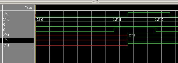
Dima P. wrote:
> the signal is red (before first clock). Why?
I explained before.
Which value do you expect and why?
i try to initialize value in dff.v
1 | module dff(clk, dout); |
2 | input clk; |
3 | output reg [1:0] dout; |
4 | |
5 | reg [1:0] din; |
6 | initial |
7 | begin |
8 | din[0] = 1'b0; |
9 | din[1] = 1'b0; |
10 | end |
11 | |
12 | always @ (posedge clk) |
13 | begin |
14 | dout <= din; |
15 | end |
16 | endmodule |
testbench doesnt work
Dima P. wrote:
> testbench doesnt work
What message?

> i try to initialize value in dff.v
As you can easily see: dout is making trouble to you. And therefore you
must initialize dout. That are your flipflops!
Please log in before posting. Registration is free and takes only a minute.
Existing account
Do you have a Google/GoogleMail account? No registration required!
Log in with Google account
Log in with Google account
No account? Register here.