Hi everyone,

This is my first post and to come to the point: i need some guidance on
a project i am working on. Some ideas on how to solve it would be total
fine.
My profession as a electrochemist, needs some signal processing related
stuff, and since its a hot topic in our research group, i cant reveal
everything.

To start:

There is a system which exhibits some resonance phenomena, which i can
track with a real time spectrum analyzer. But! the frequency of this
signal is shifting with varying speed.
The goal is to track this signal with a peakfinder function, and feed
the same frequency back into to system at the same time as it is
detected.
Is this possible? Even if there is a delay in taking the samples, and
calculating the fft? i was thinking of a doppler shift compensation
stuff, which is avaible in gnu radio, but never worked with this so far.

For those who dont want to read everything:

Is it possible, to output the same frequency at the exact same time as
an observed signal which is shifting with time ?

Thank you,
Stephan
Hi Stephan,

Yes this is possible and there exist numerous solutions.

The correct search term is PLL or Phase Locked Loop.

But without more specific details (frequency and bandwidth,
speed of change, signal level and application)
it is impossible to be more specfic.

Best regards,
Udo
Hi Udo,

Thank you for your time.
- There exist numerous frequencies, and even harmonic distortion, caused
by the systems non-linearity.
- The speed of change is also specific from case to case, but is
expected to be slower than  100 kHz.

- The signal level is expected to be in the picovolt up to nanovolt
range which is amplified by a instrumentation amp (DC coupled),.. but
thats a different story.
- The SNR ratio is expected to be about 10 dB.

- The frequency range is between 10kHz up to 10 MHz, bandwith depends on
frequency resolution

- the frequency shift starts for example at 10 kHz and stops at 50 kHz
with a speed of 1kHz up to 100 kHz.

Greets Stephan
Two questions:

 - Do you have a time at the start, where you could lock to the
   one frequency of interest?

 - How long does it take for your system to change the frequency
  from 10kHz to 50 kHz in your example above (in seconds)?
1. I can observe it, with a pulse response. But if i can lock into it,

2. Thats one thing which is quiet not sure, it should be as mentioned
before slower then 100 kHz (maximum possible speed the system can
change), it depends on some chemical reactions taking place
Step 1: Run a FFT with the received signal and find the highest peak in
it.

Step 2: program a frequency synthesizer with the found frequency (either
a µC controlled PLL or a DDS oscillator)
Yeah thats and these are the first steps,
but

the sampling and fft calculation takes some time. Thats why i want to
know if it is possible to output the exact same freq. at the exact same
time as the observed frequency which is shifting with time.
If there is a too big time mismatch it doesnt work
Ste_Trat wrote:
> the sampling and fft calculation takes some time. Thats why i want to
> know if it is possible to output the exact same freq. at the exact same
> time as the observed frequency which is shifting with time.
> If there is a too big time mismatch it doesnt work

You need to define "exactly" (how much missmacht you can accept). The
missmatch can not be 0.
Test wrote:
> You need to define "exactly" (how much missmacht you can accept). The
> missmatch can not be 0.

No the mismathc could be 0, in theory at least :-)

@Stephan

I is still not clear to me how fast your response should be
and if you have an initial "quiet" time where not much
changes and during which you can find a frequency start value.
(You have said 100 kHz, but this is not a time interval,
or is the solution periodic?)

It would be important to know what physical parameter you want to
control?  Temperature maybe? Or something faster changing?

What is the hardware platform on which the system is running?
Maybe an analog solution is much simpler, especially if you
have not enough time to calculate the FFTs.

Please tell us something about your application and your
goals, otherwise this is only guessing in the dark and not many
productive ideas will result.
Attached files:
-

20180315_220148.jpg
240 KB -

20180315_220157.jpg
230 KB -

20180315_220205.jpg
240 KB

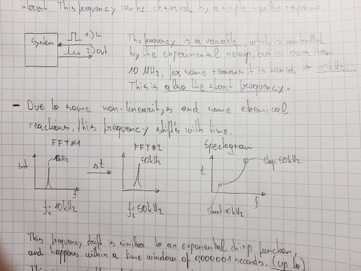
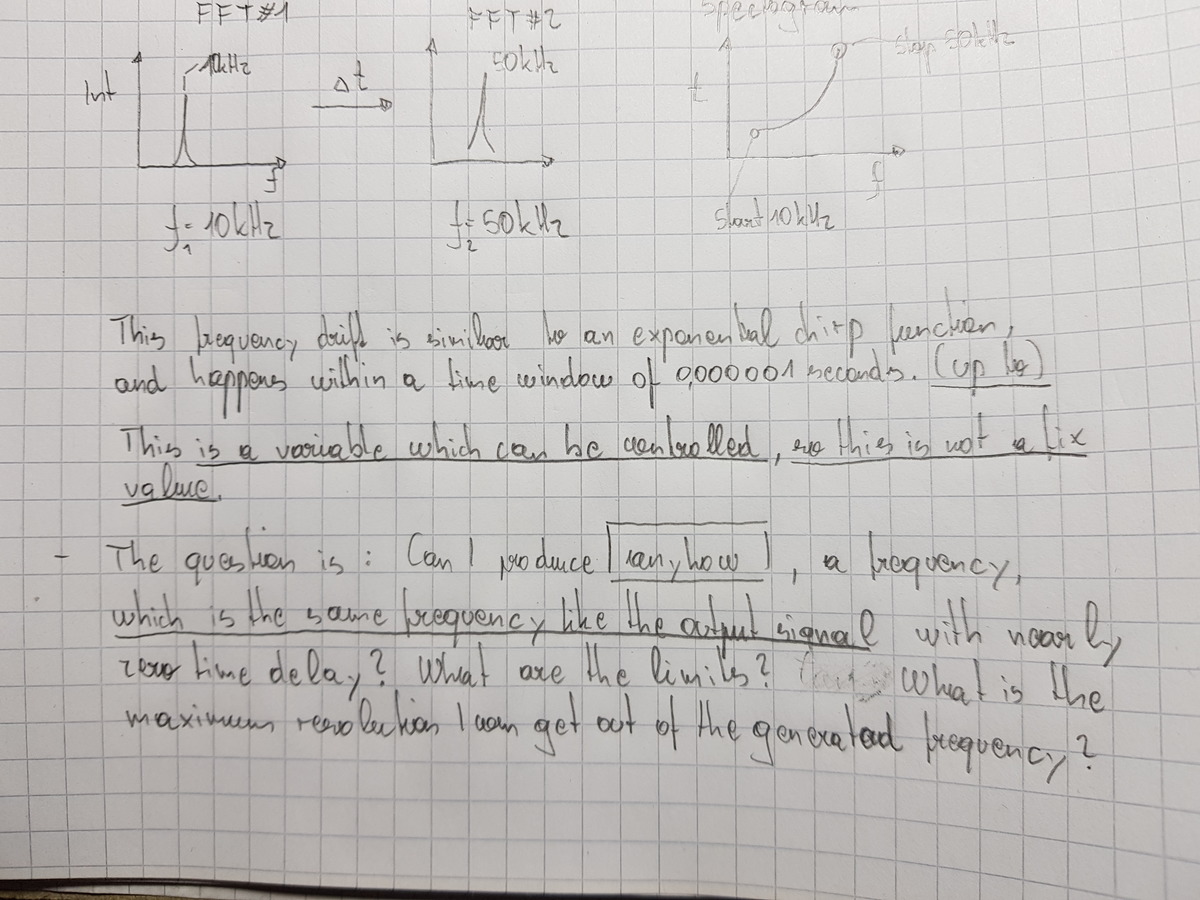
So, i have made some screenshots of a quick overview of the problem i am
faced with and hope its readable.
Since i am chemist, pictures are the prefered way to explain, to
interpret and to solve problems.

The main goal is to answer the question(s), there are literally no
restrictions, of how to implement it.

P.s.
- i cant talk about the application
- the output is just a voltage, the system works totally fine with this
changes and everything else.
-its really only about that frequency feedback and minimizing the time
delay thing.
Feeding the measured frequency back directly has the possibility for the
lowest delay.

Trying to interpret the handwritten notes i summarize:

The DUT is excited with a pulse.

The response is similar to a chirp-style signal starting at 10Khz going
to 50Khz within 1us?

The instantaneous frequency of this response has to be extracted with
minimal delay/distortion.

The aim is to reduce measurement noise, clean up the signal.

So this is where the trade off needs to be made: Tracking
distortion/delay vs. reduction in noise.

Using DFTs for that seems inappropriate, because of the trade off time
vs. frequency resolution.

One way i can think of is modeling the DUT response with one variable,
lets say "f", and build a detector/feed back loop around which adjusts
"f" by comparing the measured data against the modeled output.

The more sophisticated/detailed the model gets (more variables, longer
time - view it over many responses, not just one) the touchier it gets
and the better it needs to match the DUT but the more S/N improvement it
may give.

The model/observer approach.

The key here is to model the DUT, track various slowly changing
variables of it (filter out noise over time) to extract quickly changing
variable(s) of interest with improved S/N compared to the raw
measurement.
Please log in before posting. Registration is free and takes only a minute.
Existing account
Do you have a Google/GoogleMail account? No registration required!
Log in with Google account
Log in with Google account
No account? Register here.