EmbDev.net

Forum: FPGA, VHDL & Verilog simple syntax error near clk


von Rock B. (rocko445)


Rate this post
useful
not useful
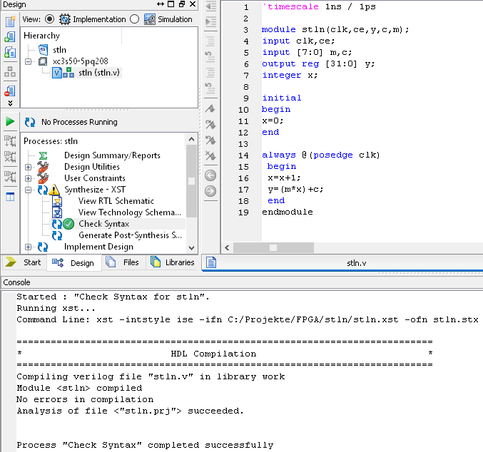
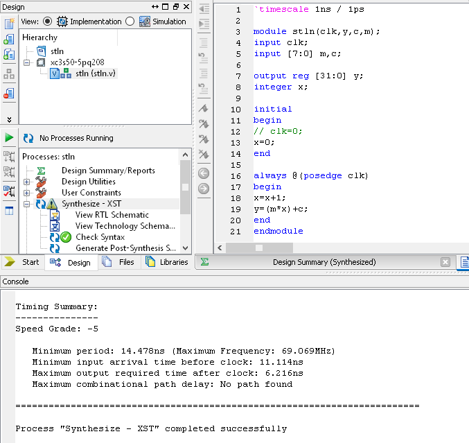
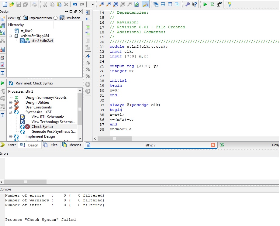
Hello , for this simple code i get these  two errors,where did i go 
wrong?
Thanks

ERROR:HDLCompiler:806 - "D:\Users\st_line_demo\stln.v" Line 14: Syntax 
error near "clk".

ERROR:HDLCompiler:598 - "D:\Users\st_line_demo\stln.v" Line 3: Module 
<stln> ignored due to previous errors.
1
`timescale 1ns / 1ps
2
3
module stln(clk,ce,y,c,m);
4
input clk,ce;
5
input [7:0] m,c;
6
output reg [31:0] y;
7
integer x;
8
9
initial
10
begin
11
x=0;
12
end
13
14
always @(postedge clk)
15
 begin 
16
 x=x+1;
17
 y=(m*x)+c;
18
 end
19
 endmodule

von Lothar M. (Company: Titel) (lkmiller) (Moderator)


Rate this post
useful
not useful
Rock B. wrote:
> postedge
Really?

von Rock B. (rocko445)


Attached files:

Rate this post
useful
not useful
Hello Lothar, i saw my mistake , now as you can see in the attached 
photo,
there is no errors but Xilinx still shown red ex sign
what could be done?

Thanks

von ElKo (Guest)


Rate this post
useful
not useful
Hint: Read the full ouptut in the tab "Console" and not only errors. Try 
to understand all messages. By doing so you should find the pointer to 
the issue.

von Lothar M. (Company: Titel) (lkmiller) (Moderator)


Attached files:

Rate this post
useful
not useful
Rock B. wrote:
> what could be done?
Rerun the process? Looking for the console messages?

von Rock B. (rocko445)


Rate this post
useful
not useful
Hello , from this consol massage i can see some points ,
is the problem in the clocks?


1.WARNING:Xst:647 - Input <ce> is never used.

2.
Asynchronous Control Signals Information:
----------------------------------------
No asynchronous control signals found in this design

Timing Summary:
---------------
Speed Grade: -3

   Minimum period: 7.472ns (Maximum Frequency: 133.831MHz)
   Minimum input arrival time before clock: 5.780ns
   Maximum output required time after clock: 0.640ns
   Maximum combinational path delay: No path found

======================================================================== 
=

Process "Synthesize - XST" failed


************************************************************************ 
*****

Started : "Synthesize - XST".
Running xst...
Command Line: xst -intstyle ise -ifn "D:/Users/st_line/stln.xst" -ofn 
"D:/Users/st_line/stln.syr"
Reading design: stln.prj

======================================================================== 
=
*                          HDL Parsing 
*
======================================================================== 
=
Analyzing Verilog file "D:\Users\st_line\stln.v" into library work
Parsing module <stln>.

======================================================================== 
=
*                            HDL Elaboration 
*
======================================================================== 
=

Elaborating module <stln>.

======================================================================== 
=
*                           HDL Synthesis 
*
======================================================================== 
=

Synthesizing Unit <stln>.
    Related source file is "D:\Users\st_line\stln.v".
WARNING:Xst:647 - Input <ce> is never used. This port will be preserved 
and left unconnected if it belongs to a top-level block or it belongs to 
a sub-block and the hierarchy of this sub-block is preserved.
    Found 32-bit register for signal <y>.
    Found 32-bit register for signal <x>.
    Found 32-bit adder for signal <x[31]_GND_1_o_add_1_OUT> created at 
line 35.
    Found 32-bit adder for signal <m[7]_GND_1_o_add_3_OUT> created at 
line 36.
    Found 8x32-bit multiplier for signal <n0010> created at line 36.
    Summary:
  inferred   1 Multiplier(s).
  inferred   2 Adder/Subtractor(s).
  inferred  64 D-type flip-flop(s).
Unit <stln> synthesized.

======================================================================== 
=
HDL Synthesis Report

Macro Statistics
# Multipliers                                          : 1
 32x8-bit multiplier                                   : 1
# Adders/Subtractors                                   : 2
 32-bit adder                                          : 2
# Registers                                            : 2
 32-bit register                                       : 2

======================================================================== 
=

======================================================================== 
=
*                       Advanced HDL Synthesis 
*
======================================================================== 
=


Synthesizing (advanced) Unit <stln>.
The following registers are absorbed into counter <x>: 1 register on 
signal <x>.
Unit <stln> synthesized (advanced).

======================================================================== 
=
Advanced HDL Synthesis Report

Macro Statistics
# Multipliers                                          : 1
 32x8-bit multiplier                                   : 1
# Adders/Subtractors                                   : 2
 32-bit adder                                          : 2
# Counters                                             : 1
 32-bit up counter                                     : 1
# Registers                                            : 32
 Flip-Flops                                            : 32

======================================================================== 
=

======================================================================== 
=
*                         Low Level Synthesis 
*
======================================================================== 
=

Optimizing unit <stln> ...

Mapping all equations...
Building and optimizing final netlist ...
Found area constraint ratio of 100 (+ 5) on block stln, actual ratio is 
0.

Final Macro Processing ...

======================================================================== 
=
Final Register Report

Macro Statistics
# Registers                                            : 64
 Flip-Flops                                            : 64

======================================================================== 
=

======================================================================== 
=
*                           Partition Report 
*
======================================================================== 
=

Partition Implementation Status
-------------------------------

  No Partitions were found in this design.

-------------------------------

======================================================================== 
=
*                            Design Summary 
*
======================================================================== 
=

Clock Information:
------------------
-----------------------------------+------------------------+-------+
Clock Signal                       | Clock buffer(FF name)  | Load  |
-----------------------------------+------------------------+-------+
clk                                | BUFGP                  | 64    |
-----------------------------------+------------------------+-------+

Asynchronous Control Signals Information:
----------------------------------------
No asynchronous control signals found in this design

Timing Summary:
---------------
Speed Grade: -3

   Minimum period: 7.472ns (Maximum Frequency: 133.831MHz)
   Minimum input arrival time before clock: 5.780ns
   Maximum output required time after clock: 0.640ns
   Maximum combinational path delay: No path found

======================================================================== 
=

Process "Synthesize - XST" failed

von Andy (Guest)


Rate this post
useful
not useful
Use <= to write to a register, not the blocking = operators.

I would write it like that:
1
module stln(clk,ce,y,c,m);
2
 input clk,ce;
3
 input [7:0] m,c;
4
 output reg [31:0] y;
5
6
 reg [31:0] x = 0;
7
8
 always @(posedge clk) begin 
9
   x <= x+1;
10
   y <= (m*x)+c;
11
 end
12
13
endmodule

von Rock B. (rocko445)


Rate this post
useful
not useful
Hello, i think that the problem is that the "clk" variable is not 
defined as clock with period.
how can i define the clk  in ISE Xilinx?

Thanks

module stln(clk,y,c,m);
input clk;
input [7:0] m,c;

output reg [31:0] y;
integer x;

initial
begin
clk=0;
x=0;
end

always @(posedge clk)
begin
x=x+1;
y=(m*x)+c;
end
endmodule

von Lothar M. (Company: Titel) (lkmiller) (Moderator)


Attached files:

Rate this post
useful
not useful
Rock B. wrote:
> Hello, i think that the problem is that the "clk" variable is not
> defined as clock with period.
You're digging at the wrong place. Thats NOT the problem. The clock 
usually is a input and comes from a oscillator or a similar source.

> how can i define the clk  in ISE Xilinx?
It an input and when you write "posedge" or "negedge" then you invoke 
that signal as a clock to some flipflops.

After correcting that assignment to the clk signal it get a successful 
synthesizers run with only one warnig:
1
Synthesizing Unit <stln>.
2
    Related source file is "stln.v".
3
WARNING:Xst:643 - "stln.v" line 19: The result of a 32x9-bit multiplication is partially used.

I would set up a new project and copy the source to it. Maybe you 
flipped over some switches in the configuration to a faluty position...

von Rock B. (rocko445)


Attached files:

Rate this post
useful
not useful
i tried to copy paste the code again,its not working.
i attached the print screen
my new code and the console massage

`timescale 1ns / 1ps
//////////////////////////////////////////////////////////////////////// 
//////////
// Company:
// Engineer:
//
// Create Date:    15:06:30 02/07/2018
// Design Name:
// Module Name:    stln
// Project Name:
// Target Devices:
// Tool versions:
// Description:
//
// Dependencies:
//
// Revision:
// Revision 0.01 - File Created
// Additional Comments:
//
//////////////////////////////////////////////////////////////////////// 
//////////
module stln2(clk,y,c,m);
input clk;
input [7:0] m,c;

output reg [31:0] y;
integer x;

initial
begin
x=0;
end

always @(posedge clk)
begin
x=x+1;
y=(m*x)+c;
end
endmodule


*************************************

Started : "Check Syntax for stln2".
Running xst...
Command Line: xst -intstyle ise -ifn D:/Users/st_line2/stln2.xst -ofn 
stln2.stx
Reading design: stln2.prj

======================================================================== 
=
*                          HDL Parsing 
*
======================================================================== 
=
Analyzing Verilog file "D:\Users\st_line2\stln2.v" into library work
Parsing module <stln2>.


Total REAL time to Xst completion: 3.00 secs
Total CPU time to Xst completion: 3.02 secs

-->

Total memory usage is 219344 kilobytes

Number of errors   :    0 (   0 filtered)
Number of warnings :    0 (   0 filtered)
Number of infos    :    0 (   0 filtered)


Process "Check Syntax" failed

von Lothar M. (Company: Titel) (lkmiller) (Moderator)


Rate this post
useful
not useful
Rock B. wrote:
> i tried to copy paste the code again,its not working.
Did you start a completely NEW design?
As I said: the problem is NOT in your code.

von Rock B. (rocko445)


Rate this post
useful
not useful
Thank you very much, i will try other platforms.

Please log in before posting. Registration is free and takes only a minute.
Existing account
Do you have a Google/GoogleMail account? No registration required!
Log in with Google account
No account? Register here.