Hello there, have somebody code for that? I want it for Quartus
program!! Thanks a lot
It is negated R and negated S and flip flop based on NAND..
I don't know how to realize it. I have sent that code to my teacher and
she said: It isnt that what she need...
1 | library IEEE; |
2 | use IEEE.STD_LOGIC_1164.ALL; |
3 | use IEEE.STD_LOGIC_ARITH.ALL; |
4 | use IEEE.STD_LOGIC_UNSIGNED.ALL; |
5 | |
6 | entity rs_nand is |
7 | Port ( |
8 | r,s,clk : in STD_LOGIC; |
9 | q,qb : inout STD_LOGIC |
10 | );
|
11 | end rs_nand; |
12 | |
13 | |
14 | architecture rs_nand_arch of rs_nand is |
15 | |
16 | signal temp1,temp2:STD_LOGIC; |
17 | |
18 | component nand21 |
19 | port( |
20 | a,b: in STD_LOGIC; |
21 | y:out STD_LOGIC |
22 | );
|
23 | end component; |
24 | |
25 | begin
|
26 | n1: nand21 port map(a=>r,b=>clk,y=>temp1); |
27 | n2: nand21 port map(a=>clk,b=>s,y=>temp2); |
28 | n3: nand21 port map(a=>temp1,b=>qb,y=>q); |
29 | n4: nand21 port map(a=>q,b=>temp2,y=>qb); |
30 | |
31 | end rs_nand_arch; |
32 | |
33 | |
34 | library IEEE; |
35 | use IEEE.STD_LOGIC_1164.ALL; |
36 | use IEEE.STD_LOGIC_ARITH.ALL; |
37 | use IEEE.STD_LOGIC_UNSIGNED.ALL; |
38 | |
39 | entity nand21 is |
40 | Port ( |
41 | a,b : in STD_LOGIC; |
42 | y : out STD_LOGIC |
43 | );
|
44 | end nand21; |
45 | |
46 | architecture nand_arch of nand21 is |
47 | begin
|
48 | y <= a nand b; |
49 | end nand_arch; |
Martin wrote:
> It is negated R and negated S and flip flop based on NAND..
Maybe you can post the whole piece of homework?
And maybe its related to some excersie before it?

Those packages are absolutely needless here because no kind of any
calculation is done:
> use IEEE.STD_LOGIC_ARITH.ALL;
> use IEEE.STD_LOGIC_UNSIGNED.ALL;

One word to your port list:
> r,s,clk : in  STD_LOGIC;
clk? For what?


> It isnt that what she need...
Thats all?
Hey there, i got code.. Now i want testbench for it.. can you help me?!
Thanks!
1 | library IEEE; |
2 | use IEEE.STD_LOGIC_1164.ALL; |
3 | use IEEE.STD_LOGIC_ARITH.ALL; |
4 | use IEEE.STD_LOGIC_UNSIGNED.ALL; |
5 | |
6 | entity rs_nand is |
7 | Port ( |
8 | r,s: in STD_LOGIC; |
9 | q,qb : inout STD_LOGIC |
10 | );
|
11 | end rs_nand; |
12 | |
13 | |
14 | architecture rs_nand_arch of rs_nand is |
15 | |
16 | signal tmp_q, tmp_qb : STD_LOGIC; |
17 | |
18 | begin
|
19 | tmp_q <= s NAND tmp_qb; |
20 | tmp_qb <= r NAND tmp_q; |
21 | |
22 | q <= tmp_q; |
23 | qb <= tmp_qb; |
24 | |
25 | end rs_nand_arch; |
Martin wrote:
> can you help me?! Thanks!
For sure.
Start with something and when encounter a specific problem, THEN ask.
But don't try that "who is doing my homework" story...

> q,qb : inout STD_LOGIC
That is no geood design practice.
Why the heck should q and qb have an input function? Use a buffer or
an out port.
Sir. We don't know how to program in VHDL. In our school we are only
learning to read what is in code and of what it is doing.. They want
from us to make Rnot Rnot flip flop with test bench that can be tested
in ModelSim Altera of Quartus 13.1 SP. I don't know what to do. With
outputs you are true.
Attached files:
-

wf_tb_rs_flipflop.PNG
2.6 KB
Martin wrote:
> I don't know what to do.
So first start with a empty "testbench" how it can be found everywhere
in books and on the internet: a VHDL file with an empty port list, in
which the DUT (device under test) is invoked as a component. Thenn add
some local signals, connect them to the flipflop ports and generate a
test pattern for the two inputs.
The whole test bench can be done in somewhat around 30 lines here,
because in the first step you don't need to verify the results, instead
just generate a waveform in the simulator.

It took me about 5 minutes, but it will help you no further when I
just give you that "testbench". So start with something and then we
discuss.

BTW: I attached the corrected RS flipflop file. The arith package was
unnecessary also...
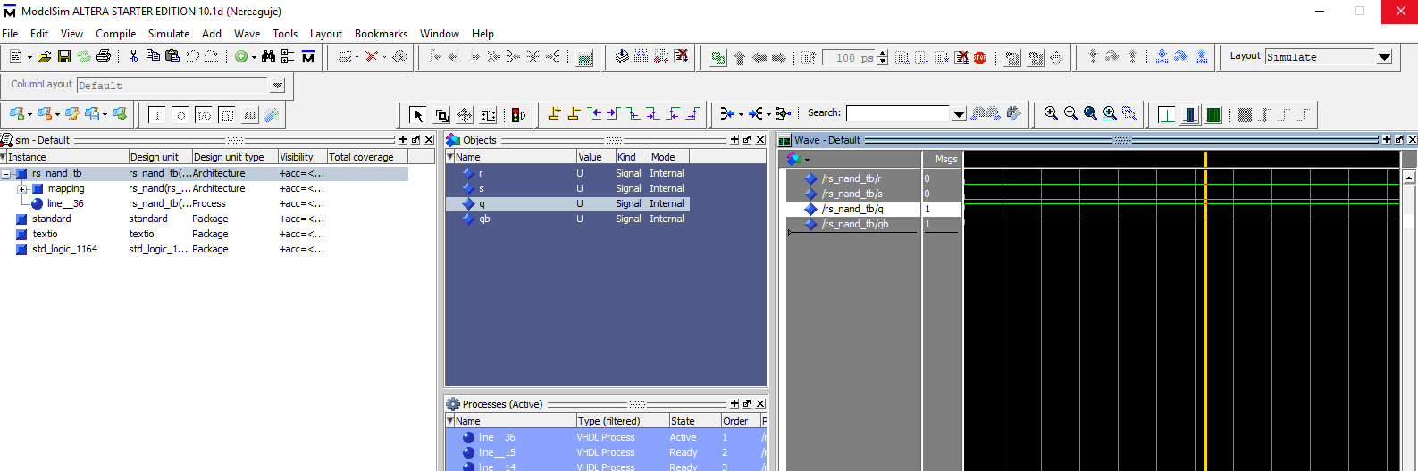
Hello there, thanks for reply, code working good and Waveform simulation
too, i tried to make test bench file, but i have problems with it.. It
draw something in Altera ModelSim. I zoomed to full but i got there only
"bars" from left to right full of green color.
I remember we had one homework months ago and there was something like
UUT in test bench and i wrote it to Assignments --> Settings --> Test
bench file but u dont know where take it now.
Actual VHDL TB code:
1 | library IEEE; |
2 | use IEEE.STD_LOGIC_1164.ALL; |
3 | entity rs_nand is |
4 | port(r, s : in std_logic; |
5 | q, qb : out std_logic); |
6 | end rs_nand; |
7 | |
8 | architecture rs_nand_arch of rs_nand is |
9 | signal tmp_q, tmp_qb : STD_LOGIC; |
10 | begin
|
11 | tmp_q <= s NAND tmp_qb; |
12 | tmp_qb <= r NAND tmp_q; |
13 | |
14 | q <= tmp_q; |
15 | qb <= tmp_qb; |
16 | end rs_nand_arch; |
17 | --------------------------------
|
18 | library ieee; |
19 | use ieee.std_logic_1164.all; |
20 | |
21 | entity rs_nand_tb is |
22 | end rs_nand_tb ; |
23 | architecture tb of rs_nand_tb is |
24 | component rs_nand is |
25 | port(r, s : in std_logic; |
26 | q, qb : out std_logic); |
27 | end component; |
28 | -------------
|
29 | signal r, s, q, qb : std_logic; |
30 | -------------
|
31 | begin
|
32 | mapping: rs_nand port map(r, s, q, qb); |
33 | |
34 | process
|
35 | |
36 | begin
|
37 | -------------TEST 1
|
38 | s <= '0'; |
39 | r <= '0'; |
40 | wait for 10 ns; |
41 | assert(q = '1') report "Error 1" severity error; |
42 | assert(qb = '1'); |
43 | ----------TEST 2
|
44 | s <= '0'; |
45 | r <= '1'; |
46 | wait for 10 ns; |
47 | assert(q = '1'); |
48 | assert(qb = '0'); |
49 | ----------TEST 3
|
50 | s <= '1'; |
51 | r <= '0'; |
52 | wait for 10 ns; |
53 | assert(q = '0'); |
54 | assert(qb = '1'); |
55 | ----------TEST 4
|
56 | s <= '1'; |
57 | r <= '1'; |
58 | wait for 10 ns; |
59 | assert(q = q); |
60 | assert(qb = not q); |
61 | |
62 | end process; |
63 | end tb; |
64 | configuration cfg_tb of rs_nand_tb is |
65 | for tb |
66 | end for; |
67 | end cfg_tb; |
Attached files:
-

testbench.PNG
55 KB
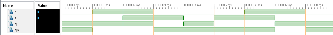
It is working! But i haven't edited test bench file. That time ago it
draws full lines, like 0 and 1 together with that "width" between them.
Now it looks good, But why it didn't automatically change values?
Attached files:
-

testbench.PNG
33 KB
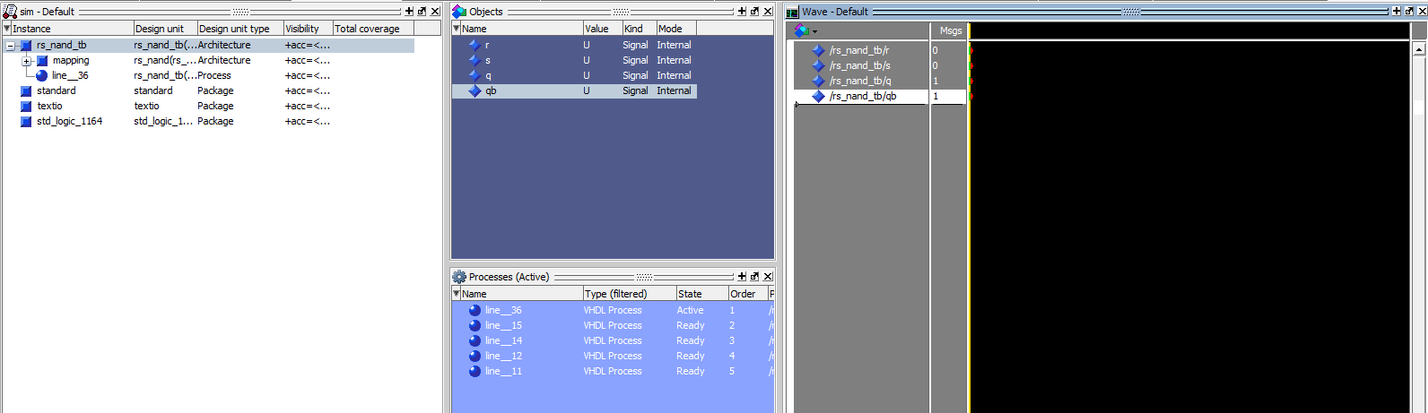
Again something bad happened. I click on Zoom full and nothing
happening.
Martin wrote:
> It is working!
You are very right. The simulator is running. Try hitting the STOP
button. Maybe then the scren is updated...
Attached files:
-

testbench.PNG
60 KB
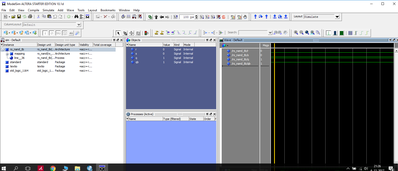
Yes, i click on stop and then Zoom. But values didn't change. What must
i change in TestBench file to make something like randomize after 50ns
etc.. I am very happy for that i alone wrote whole TestBench script.
Attached files:
-

ISIM_wf_rsff.PNG
57 KB
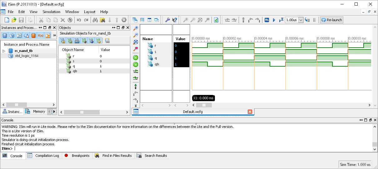
I do not know whats going wrong with ModelSim, but your files are doing
as expected on ISIM...
Attached files:
-

nand_simulation.png
26 KB
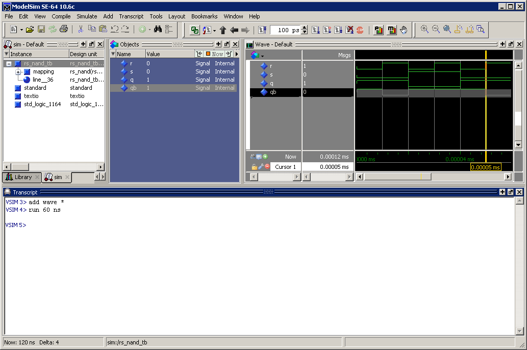
The files work perfectly in modelsim too:
1 | $ vcom nand.vhd |
2 | vcom nand.vhd |
3 | Model Technology ModelSim SE-64 vcom 10.6c Compiler 2017.07 Jul 26 2017 |
4 | -- Loading package STANDARD |
5 | -- Loading package TEXTIO |
6 | -- Loading package std_logic_1164 |
7 | -- Compiling entity rs_nand |
8 | -- Compiling architecture rs_nand_arch of rs_nand |
9 | -- Compiling entity rs_nand_tb |
10 | -- Compiling architecture tb of rs_nand_tb |
11 | -- Compiling configuration cfg_tb |
12 | -- Loading entity rs_nand_tb |
13 | -- Loading architecture tb of rs_nand_tb |
14 | -- Loading entity rs_nand |
15 | Errors: 0, Warnings: 0 |
16 | |
17 | $ vsim -gui rs_nand_tb |
18 | |
19 | vsim> add wave * |
20 | vsim> run 60 ns |
Use the zoom fit function in wave window to show everything.

Duke
Attached files:
-

testbench.PNG
3.4 KB
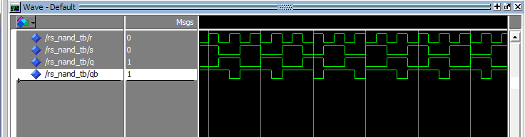
Working! THanks a lot. Problem was i have it so much Zoomed in... Thanks
a lot for your help!
Hey, what must i add to my code and how to make it correctly?!
Teacher told me that: I have RnotSnot, but it is negated RS. So i must
add to code RS too. For that i must make invertor.
I tried
r <= not rnot
s <= not snot
VHDL Compilation error: Error (10568): VHDL error at rs_nand.vhd(14):
can't write to interface object "r" of mode IN

i cannot negate it, because it is input. What now?
1 | library IEEE; --kniznica IEEE |
2 | use IEEE.STD_LOGIC_1164.ALL; --pouzitie IEEE.STD_LOGIC pre vyuzitie STD_LOGIC FUNKCII |
3 | |
4 | entity rs_nand is -- popis entity |
5 | Port (r,s,rnot,snot: in STD_LOGIC; -- definovany port s log.vstupmi R, S |
6 | q,qb : out STD_LOGIC); -- VYSTUPY Q QB |
7 | end rs_nand; --koniec popisu entity |
8 | |
9 | architecture rs_nand_arch of rs_nand is --popis architektury |
10 | |
11 | signal tmp_q, tmp_qb : STD_LOGIC; -- vytvorenie logickych signalov tmp_q a tmp_qb |
12 | |
13 | begin
|
14 | r <= not rnot; |
15 | s <= not snot; |
16 | tmp_q <= snot NAND tmp_qb; -- popis signalu architektury na NAND hradle |
17 | tmp_qb <= rnot NAND tmp_q; -- popis signalu architektury na NAND hradle |
18 | |
19 | q <= tmp_q; -- priradenie signalu tmp_q pre vystup q |
20 | qb <= tmp_qb; -- priradenie signalu tmp_qb pre vystup qb |
21 | end rs_nand_arch; --koniec popisu architektury |
Martin wrote:
> can't write to interface object "r" of mode IN
>  i cannot negate it, because it is input. What now?
Use "brain 1.0" and start thinking. If thats way tooooooo difficult,
then simply place this lines to the correct position:
1 | Port (rnot,snot: in STD_LOGIC; |
2 | ...
|
3 | signal r,s : std_logic; |
4 | ...
|
5 | r <= not rnot; |
6 | s <= not snot; |
> I tried
Bad idea.

> r,s,rnot,snot: in  STD_LOGIC;
Take any beginners book about logic and have a look at the RS flipflop.
How many inputs does it have?
Right: two, in numbers 2.
Why does your RS flipflop have 4 inputs?
Altera ModelSim simulation didnt work!
Can you please help me?!
VHDL file:
1 | library IEEE; --kniznica IEEE |
2 | use IEEE.STD_LOGIC_1164.ALL; --pouzitie IEEE.STD_LOGIC pre vyuzitie STD_LOGIC FUNKCII |
3 | |
4 | entity rs_nand is -- popis entity |
5 | Port (rnot,snot: in STD_LOGIC; -- definovany port s log.vstupmi R, S |
6 | q,qb : out STD_LOGIC); -- VYSTUPY Q QB |
7 | end rs_nand; --koniec popisu entity |
8 | |
9 | architecture rs_nand_arch of rs_nand is --popis architektury |
10 | signal tmp_q, tmp_qb : STD_LOGIC; -- vytvorenie logickych signalov tmp_q a tmp_qb |
11 | |
12 | signal r,s : STD_LOGIC; |
13 | |
14 | |
15 | begin
|
16 | r <= not rnot; |
17 | s <= not snot; |
18 | |
19 | tmp_q <= snot NAND tmp_qb; -- popis signalu architektury na NAND hradle |
20 | tmp_qb <= rnot NAND tmp_q; -- popis signalu architektury na NAND hradle |
21 | |
22 | q <= tmp_q; -- priradenie signalu tmp_q pre vystup q |
23 | qb <= tmp_qb; -- priradenie signalu tmp_qb pre vystup qb |
24 | end rs_nand_arch; --koniec popisu architektury |
TB file:
1 | library IEEE; --kniznica |
2 | use IEEE.STD_LOGIC_1164.ALL; --pouzitie log. funkcii STD_LOGIC |
3 | entity rs_nand is --opis entity |
4 | port(rnot, snot : in std_logic; |
5 | q, qb : out std_logic); |
6 | end rs_nand; |
7 | |
8 | architecture rs_nand_arch of rs_nand is |
9 | signal tmp_q, tmp_qb : STD_LOGIC; |
10 | signal r, s : STD_LOGIC; |
11 | begin
|
12 | tmp_q <= snot NAND tmp_qb; |
13 | tmp_qb <= rnot NAND tmp_q; |
14 | r <= not rnot; |
15 | s <= not snot; |
16 | q <= tmp_q; |
17 | qb <= tmp_qb; |
18 | end rs_nand_arch; |
19 | --------------------------------
|
20 | library ieee; |
21 | use ieee.std_logic_1164.all; |
22 | |
23 | entity rs_nand_tb is --entita testbench |
24 | end rs_nand_tb ; |
25 | architecture tb of rs_nand_tb is --architektura |
26 | component rs_nand is -- komponent rs_nand je komponentom architektury tb, ktora je pod entitou rs_nand_tb |
27 | port(rnot, snot : in std_logic; --port komponentu s vstupmi |
28 | q, qb : out std_logic); --vystupmi |
29 | end component; --uknceny popis komponentu |
30 | -------------
|
31 | signal rnot, snot, q, qb : std_logic; --logicke signaly, ktore je mozne dalej opisat v port mappingu |
32 | -------------
|
33 | begin
|
34 | mapping: rs_nand port map(rnot, snot, q, qb); --mapovanie portov pre danu entitu |
35 | |
36 | process --opis procesu. V procese je kod rovnocenny |
37 | --s <= '0'; a r <= '0';
|
38 | -- je to isté ako r <= '0'; a s <= '0';
|
39 | --rychlost vykonavania krokov v procese je identicka, nezalezi na poradi, riadku v kode
|
40 | begin --zaciatok opisu procesov (ktore mozu nastat, stavy) |
41 | -------------TEST 1
|
42 | snot <= '0'; |
43 | rnot <= '0'; |
44 | wait for 10 ns; |
45 | assert(q = '1') report "Error 1" severity error; --zakazany stav |
46 | assert(qb = '1'); --funkcia assert vie nastavit stav výstupu, moze aj referovat chybu! |
47 | ----------TEST 2
|
48 | snot <= '0'; |
49 | rnot <= '1'; |
50 | wait for 10 ns; |
51 | assert(q = '1'); -- |
52 | assert(qb = '0'); |
53 | ----------TEST 3
|
54 | snot <= '1'; |
55 | rnot <= '0'; |
56 | wait for 10 ns; --10ns caka v tomto stave |
57 | assert(q = '0'); |
58 | assert(qb = '1'); |
59 | ----------TEST 4
|
60 | snot <= '1'; |
61 | rnot <= '1'; |
62 | wait for 10 ns; |
63 | assert(q = q); |
64 | assert(qb = not q); |
65 | |
66 | end process; --koniec opisu procesov |
67 | end tb; --koniec opisu architektury tb |
68 | configuration cfg_tb of rs_nand_tb is --konfiguracia test bench entity |
69 | for tb --cyklus je prazdny, nema ziadnu specificku funkciu v nasom pripade |
70 | end for; --koniec cyklu |
71 | end cfg_tb --koniec opisu konfiguracie |
Martin wrote:
> Altera ModelSim simulation didnt work!
Why? What errror messages do you get?
What do you expect? And what do you get instead?

Martin wrote:
> VHDL file:
> entity rs_nand is -- popis entity
> TB file:
> entity rs_nand is --opis entity
Why are there two entities with the same name?
To get things clear: in a beginners design in the testbench file there
is only 1 entity declaration. It is that one without ports.
Please log in before posting. Registration is free and takes only a minute.
Existing account
Do you have a Google/GoogleMail account? No registration required!
Log in with Google account
Log in with Google account
No account? Register here.