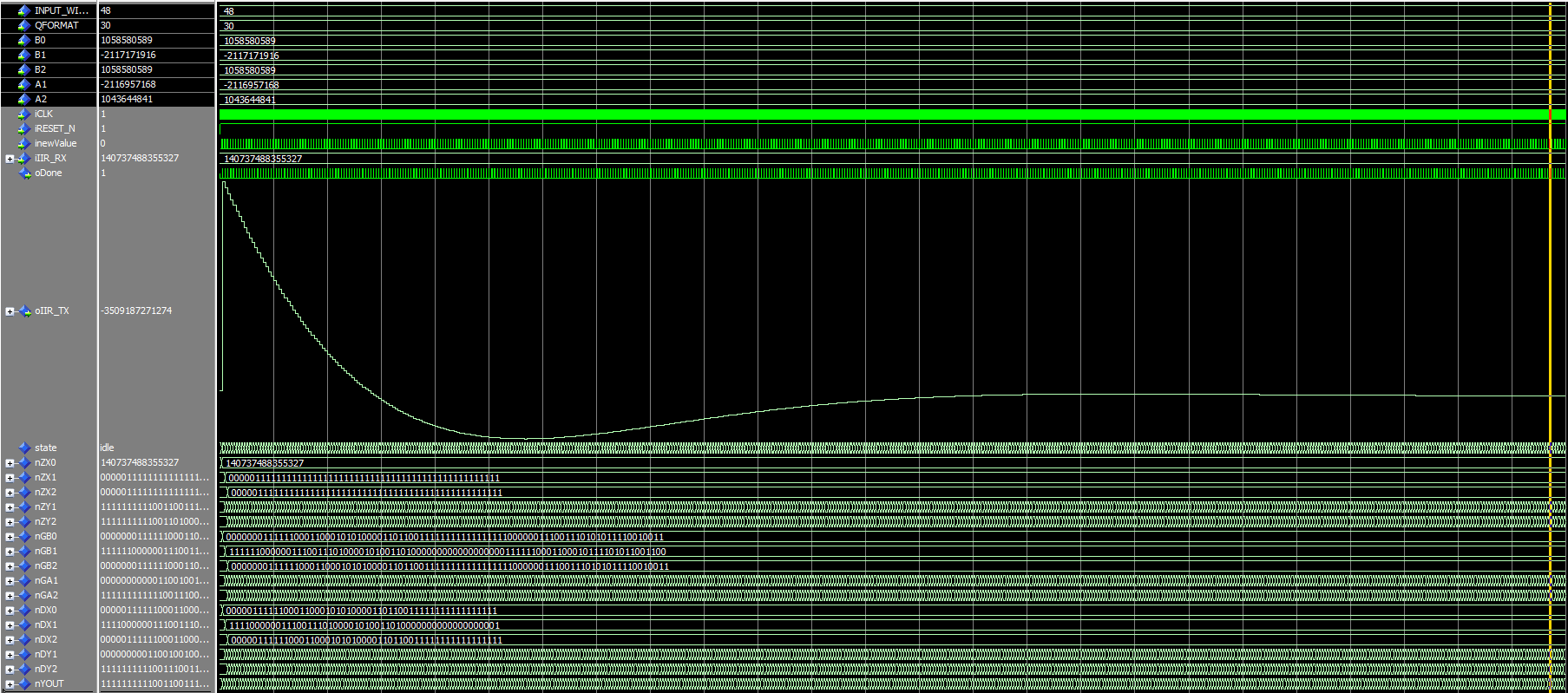
Hi guys!
I've written another IIR implementation after Directform 1 to implement
a high pass filter in my current design, the IIR will be combined with a
CIC that downsamples the sampling rate from 10MHz to ~79KHz. My filter
coefficients for the IIR are as follows:

> A1 = -1,93178
> A2 = 0,93403
> B0 = 0,96645
> B1 = -1,93291
> B2 = 0,96645

The coefficients are scaled by 2^30 and then divided by this value after
the multiplication. My implementation works with 4 guard bits, as you
can see Idle-State for nX0.

Although my simulation looks OK (to me), it doesn't work in the real
FPGA so frequencies below 1KHz are still in the signal. How do I
properly test my IIR and is there maybe something I'm missing in my
implementation?
Attached files:
-

HP_IIR_Simulation.PNG
21 KB
maybe I don't see it but somehow I miss a statement like:
 "if rising_edge(iclk) then" or " wait until rising_edge(iclk);"
 in your VHDL...
1 | process(iCLK,iRESET_N) |
2 | begin
|
3 | if(iRESET_N = '0') then |
4 | nZX0 <= (others => '0'); |
5 | nZX1 <= (others => '0'); |
6 | nZX2 <= (others => '0'); |
7 | (...) |
8 | nYOUT <= (others => '0'); |
9 | else
|
10 | //-->>> e.g.: if rising_edge(iclk) then |
11 | case state is |
examples here:
https://stackoverflow.com/questions/32717040/wait-until-rising-edgeclk-vs-if-rising-edgeclk
Bernhard K. wrote:
> maybe I don't see it but somehow I miss a statement like:
>  "if rising_edge(iclk) then" or " wait until rising_edge(iclk);"
>  in your VHDL...

Holy crap you're right!
Some code-blindness >_>
I'll compile again and report if this was my (really) stupid mistake :D
Attached files:
-

HP_Curve_simulation.png
15 KB -

HP_Filtercurve_IIRDF1.png
9.8 KB
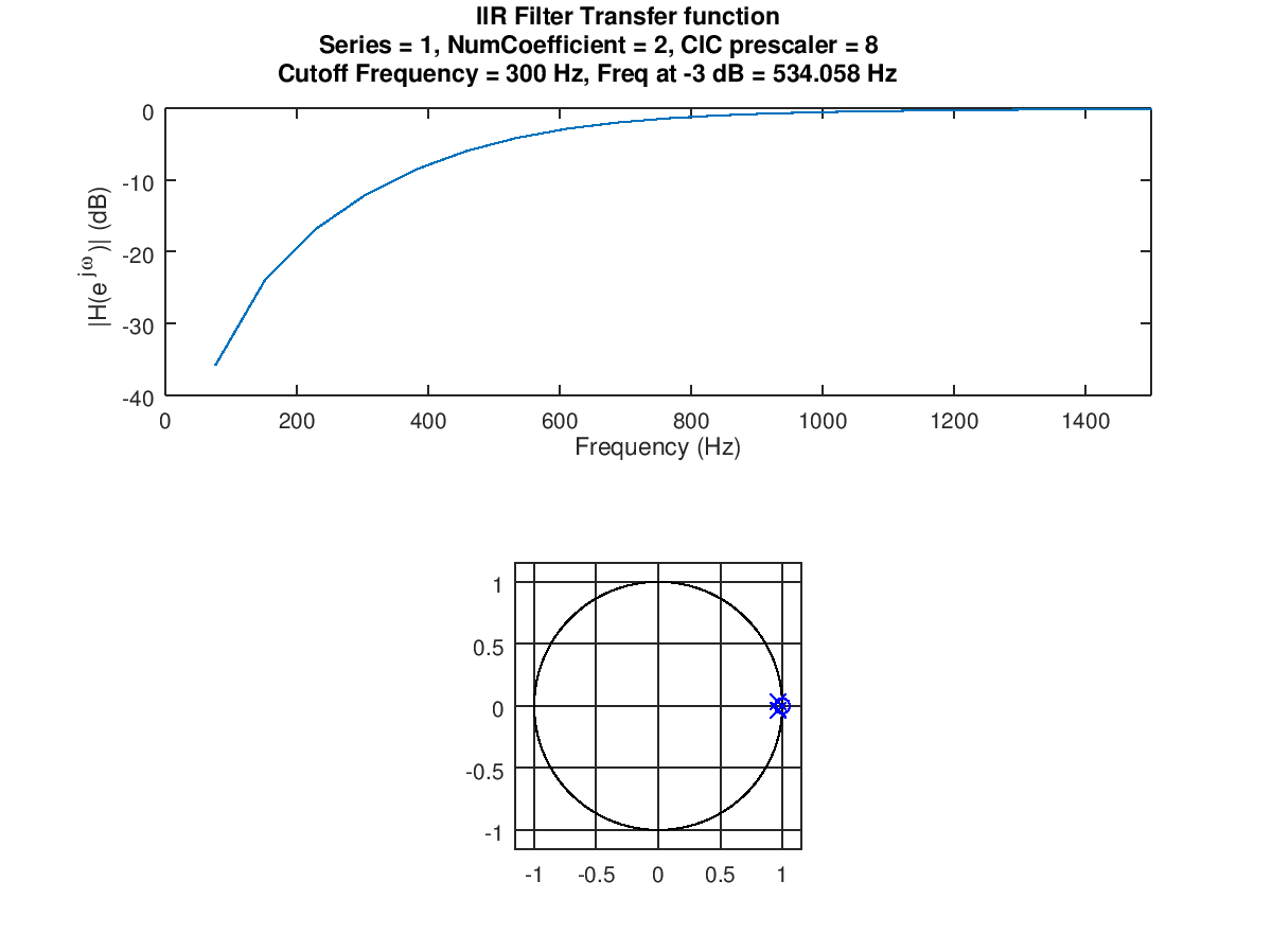
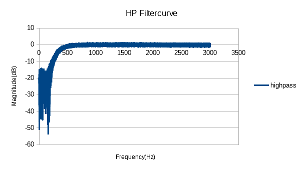
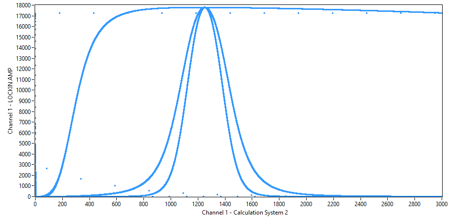
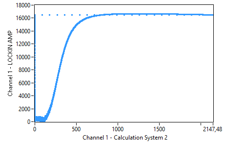
So I've implemented the clocked version :D
I did a test on the filter via an 1V amplitude and a frequency sweep
from 0 to 3000Hz. It seems to filter a bit, but not nearly as good as
I've simulated.
It looks that I'm missing something, the curve looks like I'm on track
but is my division flawed at some point?
Hi,

1. You should sum up the multiplication results and not the truncated
multiplication results. Using the truncated values will increase
rounding noise.

2. probably this line will lead to a timing violation:
  nYOUT      <=
std_logic_vector(signed(nDX0)+signed(nDX1)+signed(nDX2)-signed(nDY1)-sig
ned(nDY2));


Tom
Attached files:
-

HP_IIR_Simulation.PNG
13 KB
> 1. You should sum up the multiplication results and not the truncated
> multiplication results. Using the truncated values will increase
> rounding noise.

Done, values are a bit different and simulation looks ok, the curve
looks identical. Will try this in my FPGA, new code and testbench are
added if someone wants a closer look.

> 2. probably this line will lead to a timing violation:
>   nYOUT      <=
> std_logic_vector(signed(nDX0)+signed(nDX1)+signed(nDX2)-signed(nDY1)-sig
ned(nDY2));

According to Quartus it seems OK though, no timing problems mentioned by
TimeQuest.
Attached files:
-

IIR_async.png
6.7 KB -

IIR_state.png
2.8 KB
So far I've made two versions of the IIR, one is more async
(IIR_Biquad_II.vhd) and one uses a state machine (IIRDF1.vhd). The more
async one was derived from a project on the internet and it seems to
work as a high pass (but gives a weird curve as low pass). I've
implemented both in the FPGA and the async gives a really nice curve,
while the one with the state machine has some weird effects. Can someone
tell me why this is? I really have no clue what should cause this :-/

By the way, my own state machine implementation works fairly well as a
low pass, as you can see on the picture with the two additional signals
(2nd and 4th order LP).
"it seems to work as a high pass (but gives a weird curve as low pass)"

As I did before I would recommend that you implement a testbench to
check every bit of the computation  and compare it for example with an
implementation in lua, java or what so ever. If everything is checked in
that way there will be no more "It seems". It's a little bit of work for
the first filter, but you will easily check other filters afterwards.
Martin O. wrote:
> "it seems to work as a high pass (but gives a weird curve as low pass)"
>
> As I did before I would recommend that you implement a testbench to
> check every bit of the computation  and compare it for example with an
> implementation in lua, java or what so ever.

That's what I did, the values look quite nice though and it behaves like
a filter should do (from my understanding).
1 | 63336.30075 -126673.25685 63336.30075 -126599.2023 61211.65605 nil |
2 | K= 0 Input= 140737488355328 Output= -85901 |
3 | K= 1 Input= 140737488355328 Output= -85906 |
4 | K= 2 Input= 140737488355328 Output= -85906 |
5 | K= 3 Input= 140737488355328 Output= -85906 |
6 | K= 4 Input= 140737488355328 Output= -85906 |
7 | K= 5 Input= 140737488355328 Output= -85906 |
8 | K= 6 Input= 140737488355328 Output= -85906 |
9 | K= 7 Input= 140737488355328 Output= -85906 |
10 | K= 8 Input= 140737488355328 Output= -85906 |
11 | K= 9 Input= 140737488355328 Output= -85906 |
12 | K= 10 Input= 140737488355328 Output= -85906 |
13 | K= 11 Input= 140737488355328 Output= -85906 |
14 | K= 12 Input= 140737488355328 Output= -85906 |
15 | K= 13 Input= 140737488355328 Output= -85906 |
16 | K= 14 Input= 140737488355328 Output= -85906 |
17 | K= 15 Input= 140737488355328 Output= -85906 |
18 | K= 16 Input= 140737488355328 Output= -85906 |
19 | K= 17 Input= 140737488355328 Output= -85906 |
20 | K= 18 Input= 140737488355328 Output= -85906 |
21 | K= 19 Input= 140737488355328 Output= -85906 |
22 | K= 20 Input= 140737488355328 Output= -85906 |
23 | K= 21 Input= 0 Output= -6 |
24 | K= 22 Input= 0 Output= -1 |
25 | K= 23 Input= 0 Output= -1 |
26 | K= 24 Input= 0 Output= -1 |
27 | K= 25 Input= 0 Output= -1 |
28 | K= 26 Input= 0 Output= -1 |
29 | K= 27 Input= 0 Output= -1 |
30 | K= 28 Input= 0 Output= -1 |
31 | K= 29 Input= 0 Output= -1 |
32 | K= 30 Input= 0 Output= -1 |
33 | K= 31 Input= 0 Output= -1 |
34 | K= 32 Input= 0 Output= -1 |
35 | K= 33 Input= 0 Output= -1 |
36 | K= 34 Input= 0 Output= -1 |
37 | K= 35 Input= 0 Output= -1 |
38 | K= 36 Input= 0 Output= -1 |
39 | K= 37 Input= 0 Output= -1 |
40 | K= 38 Input= 0 Output= -1 |
41 | K= 39 Input= 0 Output= -1 |
42 | K= 40 Input= 140737488355328 Output= -85901 |
43 | K= 41 Input= 140737488355328 Output= -85906 |
44 | K= 42 Input= 140737488355328 Output= -85906 |
45 | K= 43 Input= 140737488355328 Output= -85906 |
46 | K= 44 Input= 140737488355328 Output= -85906 |
47 | K= 45 Input= 140737488355328 Output= -85906 |
48 | K= 46 Input= 140737488355328 Output= -85906 |
49 | K= 47 Input= 140737488355328 Output= -85906 |
50 | K= 48 Input= 140737488355328 Output= -85906 |
51 | K= 49 Input= 140737488355328 Output= -85906 |
52 | K= 50 Input= 140737488355328 Output= -85906 |
53 | K= 51 Input= 140737488355328 Output= -85906 |
54 | K= 52 Input= 140737488355328 Output= -85906 |
55 | K= 53 Input= 140737488355328 Output= -85906 |
56 | K= 54 Input= 140737488355328 Output= -85906 |
57 | K= 55 Input= 140737488355328 Output= -85906 |
58 | K= 56 Input= 140737488355328 Output= -85906 |
59 | K= 57 Input= 140737488355328 Output= -85906 |
60 | K= 58 Input= 140737488355328 Output= -85906 |
61 | K= 59 Input= 140737488355328 Output= -85906 |
62 | K= 60 Input= 140737488355328 Output= -85906 |
Attached files:
-

HP_IIR_Simulation.PNG
13 KB
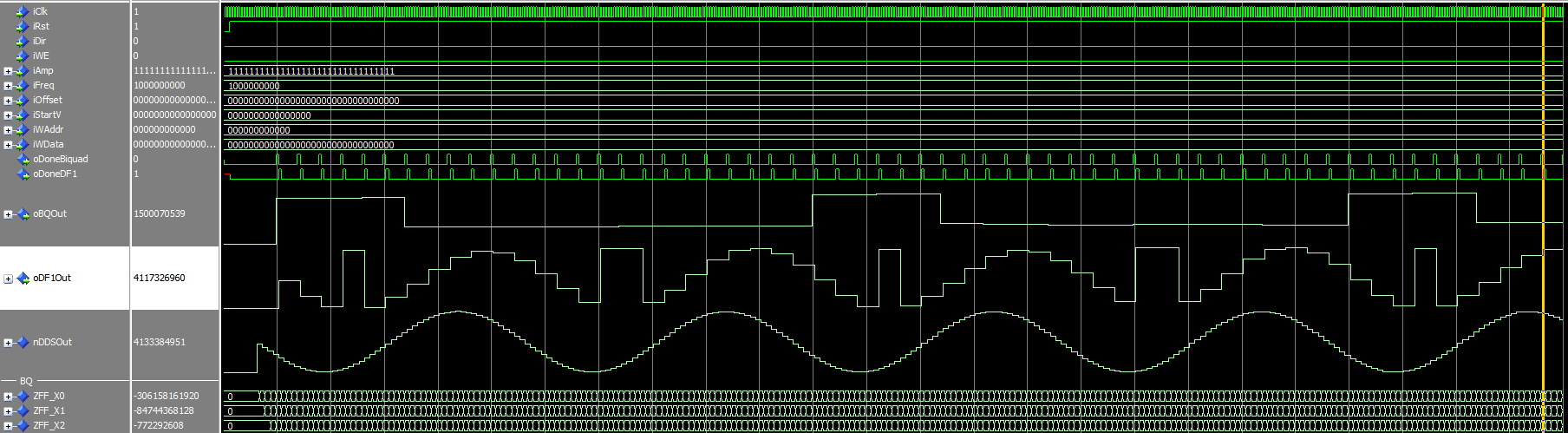
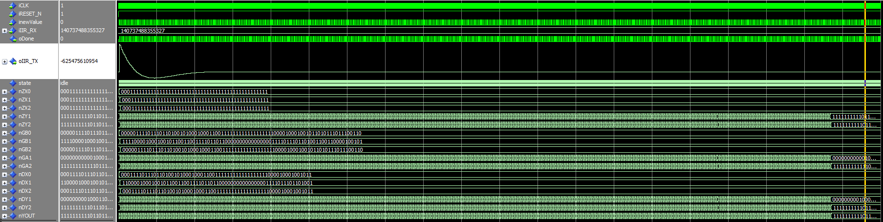
So I did a new VHDL Testbench and my simulation shows that both
implementations are not as equal as I've thought with the jumps as test
values. I'm using a DDS with 100KHz and full amplitude as Input. As you
can see in the picture, the DF1 has kind of a sign in it, which should
explain the behaviour of the filter. Now I need to find out why this is
:-/
It's probably not sufficient to qualitatively compare output values.
I know it's a pain, but sometimes it's the only cure: Compare every bit
of every arithmetic operation and variable for some (initial) steps.
It seems that an overflow is happening in the simulation, since the most
negative part of the sine is folded to a positive value.
1 | module biquad1 |
2 | #(
|
3 | parameter coeffWidth = 1, |
4 | parameter productWidth = 1, |
5 | parameter sig1Width = 1 |
6 | )
|
7 | (
|
8 | output wire [sig1Width-1: 0] IIRoutput_o , |
9 | input IIRclk_i , |
10 | input wire modeReset_i , |
11 | input wire signed [sig1Width-1: 0] IIRinput_i , |
12 | input wire signed [coeffWidth-1: 0] b0_i , |
13 | input wire signed [coeffWidth-1: 0] b1_i , |
14 | input wire signed [coeffWidth-1: 0] b2_i , |
15 | input wire signed [coeffWidth-1: 0] NEGa1_i , |
16 | input wire signed [coeffWidth-1: 0] NEGa2_i |
17 | );
|
18 | |
19 | |
20 | reg signed [sig1Width-1: 0] s1 ; |
21 | reg signed [sig1Width-1: 0] s2 ; |
22 | |
23 | wire signed [sig1Width-1: 0] vk ; |
24 | reg signed [sig1Width-1: 0] vkReg ; |
25 | reg signed [sig1Width-1: 0] xk ; |
26 | reg signed [sig1Width-1: 0] v1 ; |
27 | reg signed [sig1Width-1: 0] v2 ; |
28 | reg signed [sig1Width-1: 0] ykReg ; |
29 | |
30 | wire signed [productWidth-1: 0] productB0; |
31 | wire signed [productWidth-1: 0] productB1 ; |
32 | wire signed [productWidth-1: 0] productB2 ; |
33 | wire signed [productWidth-1: 0] productA1; |
34 | wire signed [productWidth-1: 0] productA2 ; |
35 | |
36 | assign vk = IIRinput_i+s1 ; |
37 | assign productA2 = NEGa2_i*vk ; |
38 | assign productA1 = NEGa1_i*vk ; |
39 | assign productB0 = b0_i*vkReg ; |
40 | assign productB1 = b1_i*vkReg ; |
41 | assign productB2 = b2_i*vkReg ; |
42 | |
43 | wire sampleStrobe ; |
44 | assign sampleStrobe = 1 ; |
45 | assign IIRoutput_o = ykReg ; |
46 | |
47 | always @(posedge IIRclk_i ) begin |
48 | if ( sampleStrobe ) begin |
49 | xk <= IIRinput_i ; |
50 | if ( modeReset_i ) begin |
51 | s1<=25'h0 ; |
52 | s2<=25'h0 ; |
53 | v1<=25'h0 ; |
54 | v2<=25'h0 ; |
55 | vkReg <= 0 ; |
56 | ykReg <= 0 ; |
57 | end
|
58 | else begin |
59 | s1<=s2+ productA1[25-1+16:0+16] ; |
60 | s2<= productA2[25-1+16:0+16] ; |
61 | v1<=v2 + productB1[25-1+16:0+16] ; |
62 | v2<= productB2[25-1+16:0+16] ; |
63 | vkReg <= vk ; |
64 | ykReg <= v1 + productB0[25-1+16:0+16] ; |
65 | end
|
66 | end
|
67 | end
|
So sieht meine IIR-Biquad Berechnung in Verilog aus. Mi jedem Takt wird
ein Sample berechnet.
Did something like that before, this is still directform 1 with just
some async calculations and the filter curves look the same as with my
state machine implementation. Maybe I'll try your implementation of the
DF2, but as far as I can see there is no overflow in the registers, even
with 8 guard bits there seems to be no issue. Can you provide a proper
testbench for your filter?
1 | LIBRARY ieee; |
2 | USE ieee.std_logic_1164.ALL; |
3 | use ieee.NUMERIC_STD.ALL; |
4 | use ieee.std_logic_signed.all; |
5 | |
6 | |
7 | entity IIRDF1 is |
8 | generic ( |
9 | INPUT_WIDTH : integer := 64; |
10 | QFORMAT : integer := 30; |
11 | B0 : integer := 409494; |
12 | B1 : integer := 818988; |
13 | B2 : integer := 409494; |
14 | A1 : integer := -3954428; |
15 | A2 : integer := 1398100 |
16 | );
|
17 | |
18 | port ( |
19 | iCLK : in std_logic; |
20 | iRESET_N : in std_logic; |
21 | inewValue : in std_logic; -- indicates a new input value |
22 | iIIR_RX : in std_logic_vector (INPUT_WIDTH-1 downto 0); -- singed is expected |
23 | oDone : out std_logic; -- Done Flag for next Filter |
24 | oIIR_TX : out std_logic_vector (INPUT_WIDTH-1 downto 0)-- Output |
25 | );
|
26 | end entity IIRDF1; |
27 | |
28 | architecture BEH_FixCoefficientIIR of IIRDF1 is |
29 | |
30 | constant cA1 : signed(QFORMAT+1 downto 0) := to_signed(A1,QFORMAT+2);-- A1 |
31 | constant cA2 : signed(QFORMAT+1 downto 0) := to_signed(A2,QFORMAT+2);-- A2 |
32 | constant cB0 : signed(QFORMAT+1 downto 0) := to_signed(B0,QFORMAT+2);-- B1 |
33 | constant cB1 : signed(QFORMAT+1 downto 0) := to_signed(B1,QFORMAT+2);-- B1 |
34 | constant cB2 : signed(QFORMAT+1 downto 0) := to_signed(B2,QFORMAT+2);-- B1 |
35 | |
36 | signal productA1,productA2,productB1,productB2,productB0 : std_logic_vector(INPUT_WIDTH+1+QFORMAT+2 downto 0) := (others => '0'); |
37 | signal nZX0,nZX1,nZX2,nZY1,nZY2 : std_logic_vector(INPUT_WIDTH+1 downto 0) := (others => '0'); |
38 | |
39 | begin
|
40 | productB0 <= std_logic_vector(cB0 * signed(nZX0)); |
41 | productB1 <= std_logic_vector(cB1 * signed(nZX1)); |
42 | productB2 <= std_logic_vector(cB2 * signed(nZX2)); |
43 | productA1 <= std_logic_vector(cA1 * signed(nZY1)); |
44 | productA2 <= std_logic_vector(cA2 * signed(nZY2)); |
45 | |
46 | process(iCLK,iRESET_N) |
47 | begin
|
48 | if(rising_edge(iCLK)) then |
49 | if(iRESET_N = '0') then |
50 | nZX0 <= (others => '0'); |
51 | nZX1 <= (others => '0'); |
52 | nZX2 <= (others => '0'); |
53 | nZY1 <= (others => '0'); |
54 | nZY2 <= (others => '0'); |
55 | else
|
56 | oDone <= '0'; |
57 | if(inewValue = '1') then |
58 | nZX0 <= iIIR_RX(iIIR_RX'left) & iIIR_RX(iIIR_RX'left) & iIIR_RX; |
59 | nZX1 <= nZX0; |
60 | nZX2 <= nZX1; |
61 | nZY1 <= productB0(productB0'left-2 downto QFORMAT)+productB1(productB1'left-2 downto QFORMAT)+productB2(productB2'left-2 downto QFORMAT)-productA1(productA1'left-2 downto QFORMAT)-productA2(productA2'left-2 downto QFORMAT); |
62 | oIIR_TX <= productB0(productB0'left-4 downto QFORMAT)+productB1(productB1'left-4 downto QFORMAT)+productB2(productB2'left-4 downto QFORMAT)-productA1(productA1'left-4 downto QFORMAT)-productA2(productA2'left-4 downto QFORMAT); |
63 | nZY2 <= nZY1; |
64 | oDone <= '1'; |
65 | end if; |
66 | end if; |
67 | end if; |
68 | end process; |
69 | |
70 | end architecture; |
So sieht meine Testbench aus. Die Koeffizienten sind besonders einfach
und ich teste damit die grundlegende Arithmetik. Ob Überläufe
stattfinden teste ich immer am echten Objekt. Das theoretisch im
Vorhinein zu machen ist für mich schwierig, weil ich nicht weiss, welche
Eingangssequenz die "gefährlichste" ist.
1 | module IIR1_tb; |
2 | |
3 | reg TBclk ; |
4 | parameter tck = 10; ///< clock tick |
5 | always #(tck/2) TBclk <= ~TBclk; // clocking device |
6 | |
7 | integer fd ; |
8 | |
9 | parameter productWidth = 42 ; |
10 | parameter coeffWidth = 18 ; |
11 | parameter sig1Width = 25 ; |
12 | |
13 | reg signed [sig1Width-1: 0] IIR1inPrepare ; |
14 | reg signed [sig1Width-1: 0] IIR1in ; |
15 | wire signed [sig1Width-1: 0] IIR1out ; |
16 | reg [ 32-1: 0] debug1 ; |
17 | wire sampleStrobe ; |
18 | assign sampleStrobe = 1 ; |
19 | |
20 | reg [ 8-1: 0] timer ; |
21 | |
22 | always @(posedge TBclk) begin |
23 | if ( sampleStrobe ) begin |
24 | IIR1in <= IIR1inPrepare ; |
25 | debug1 <= IIR1out ; |
26 | timer <= timer+1 ; |
27 | end
|
28 | end
|
29 | |
30 | reg signed [coeffWidth-1: 0] IIR1b0 ; |
31 | reg signed [coeffWidth-1: 0] IIR1b1 ; |
32 | reg signed [coeffWidth-1: 0] IIR1b2 ; |
33 | reg signed [coeffWidth-1: 0] IIR1a1 ; |
34 | reg signed [coeffWidth-1: 0] IIR1a2 ; |
35 | |
36 | reg modeReset ; |
37 | |
38 | red_pitaya_asg_biquad1
|
39 | #(
|
40 | .coeffWidth ( coeffWidth ), |
41 | .productWidth (productWidth), |
42 | .sig1Width (sig1Width ) |
43 | ) biquadModule1 |
44 | ( .IIRoutput_o ( IIR1out ) , |
45 | .IIRclk_i ( TBclk ) , |
46 | .modeReset_i ( modeReset ) , |
47 | .IIRinput_i ( IIR1in ) , |
48 | .b0_i ( IIR1b0 ) , |
49 | .b1_i ( IIR1b1 ) , |
50 | .b2_i ( IIR1b2 ) , |
51 | .a1_i ( IIR1a1 ) , |
52 | .a2_i ( IIR1a2 ) |
53 | ) ; |
54 | /*
|
55 | always @(posedge TBclk) begin
|
56 | $fwrite(fd, "TBdout1=%3d TBdout2=%3d TBrst1=%1d TBrst2=%1d\n",
|
57 | TBdout1,TBdout2,TBrst1,TBrst2) ;
|
58 | end
|
59 | */
|
60 | |
61 | initial begin |
62 | fd = $fopen("output.txt", "w"); |
63 | |
64 | $dumpfile("test1.vcd"); |
65 | $dumpvars(-1, IIR1_tb); |
66 | $monitor("%d in=%10d out=%10d ",timer, IIR1in ,IIR1out ); |
67 | //$monitor("%d in=%10d vk=%10d vkReg=%10d",timer, IIR1in ,vk,vkReg );
|
68 | end
|
69 | |
70 | reg signed [sig1Width-1: 0] in1 ; |
71 | reg signed [sig1Width-1: 0] in2 ; |
72 | reg signed [sig1Width-1: 0] in3 ; |
73 | always @(posedge TBclk) begin |
74 | in1<=IIR1in ; |
75 | in2<=in1 ; |
76 | end
|
77 | |
78 | always @(posedge TBclk) begin |
79 | in3<=in2 ; |
80 | end
|
81 | real rho ; |
82 | real cosphi ; |
83 | // testbench actions
|
84 | initial begin |
85 | timer=0 ; |
86 | // IIR1b0=1<<16 ; // 1.0
|
87 | // IIR1b1=( 0) ;
|
88 | // IIR1b2=( 0) ;
|
89 | |
90 | |
91 | IIR1b0=1<<16 ; // 1.0 |
92 | IIR1b1=( (1.0)*(2**16)) ; |
93 | IIR1b2=( -(0.5)*(2**16)) ; |
94 | |
95 | // rho=0.5 ;
|
96 | // cosphi=-0.5 ;
|
97 | // IIR1a1= ((-2*cosphi*rho)*(2**16)) ;
|
98 | // IIR1a2= ((rho*rho)*(2**16)) ;
|
99 | |
100 | |
101 | IIR1a1= ((-1.0)*(2**16)) ; // cos phi=sqrt(2)/2 |
102 | IIR1a2= ((0.5)*(2**16)) ; // rho=sqrt(2)/2 |
103 | |
104 | // IIR1a1= 0 ;
|
105 | // IIR1a2= 0 ;
|
106 | IIR1inPrepare <= 0 ; |
107 | TBclk = 0; |
108 | modeReset = 0; |
109 | #(tck); modeReset = 1;
|
110 | repeat(5) @(posedge TBclk); |
111 | #(tck); modeReset = 0;
|
112 | repeat(5) @(posedge TBclk); |
113 | @(negedge TBclk); |
114 | // IIR1in <= (1<<23) ;
|
115 | IIR1inPrepare <= (1600000) ; |
116 | @(negedge TBclk); |
117 | IIR1inPrepare <= 0 ; |
118 | repeat(50) @(posedge TBclk); |
119 | $fclose(fd); |
120 | $finish; |
121 | |
122 | end
|
123 | |
124 | endmodule
|
Please log in before posting. Registration is free and takes only a minute.
Existing account
Do you have a Google/GoogleMail account? No registration required!
Log in with Google account
Log in with Google account
No account? Register here.