Hi i have written a vhdl code along with the testbench..when i simulate
it in the modelSim i don't get an expected result

The VHDL Code is given below

 Library ieee;
    use ieee.std_logic_1164.all;
    entity PowerSeq is
        port(fpga_clk: in std_logic;
                Enable_Bias_1V, Enable_3V3, Enable_1P5V, Enable_1V: out
std_logic;
                PG_3V3: in std_logic);
    end PowerSeq;

    architecture MPU_PowerSeq of PowerSeq is

        signal pon_state: integer:= 0;
    begin

        process(fpga_clk)
        begin
            if(rising_edge(fpga_clk)) then

                if(pon_state = 0) then
                    Enable_3V3 <= '1';
                    Enable_1P5V <= '1';
                    Enable_1V <= '0';
                    Enable_Bias_1V <= '1';
                    pon_state <= 1;
                end if;
                    if(pon_state = 1) then
                        if(PG_3V3 = '1') then
                            Enable_1V <= '1';
                        end if;
                    end if;

                end if;
            end process;
    end MPU_PowerSeq;

------------------------------------------------------------------------
------------------------------------------------------------------------
------

 and the Test bench is also given below

  library ieee;
 use ieee.std_logic_1164.all;
 use ieee.numeric_std.all;
 use ieee.std_logic_unsigned.all;
 entity PowerSeq is
 end PowerSeq;

 architecture MPU_PowerSeq of PowerSeq is

 component Sequence is
    port(fpga_clk : in std_logic;
        Reset: in std_logic;
             Enable_Bias_1V, Enable_3V3, Enable_1P5V, Enable_1V: out
std_logic;

         PG_3V3: in std_logic);
    end component;

 signal  Reset: std_logic:= '0';
 signal  fpga_clk : std_logic:= '0';
 signal  Enable_Bias_1V: std_logic:= '0';
 signal  Enable_3V3: std_logic:= '0';
 signal  Enable_1P5V: std_logic:= '0';
 signal  Enable_1V: std_logic:= '0';
 signal  pon_state: integer:= 0;
 signal PG_3V3: std_logic:= '0';
 constant tb_time: time:= 15.5 ns;

 begin
 uut: sequence port map(
    Reset => Reset,
    fpga_clk => fpga_clk,
    Enable_Bias_1V => Enable_Bias_1V,
    Enable_3V3 => Enable_3V3,
    Enable_1P5V => Enable_1P5V,
    Enable_1V => Enable_1V,
    PG_3V3 => PG_3V3
    );

 stimlus: process
 begin
    fpga_clk <= '0' after tb_time, '1' after 2 * tb_time;
    wait for 2 * tb_time;
 end process;

 tb: process
 begin
  wait for 50 ns ;
  Reset <= '0';
  Enable_3V3 <= '0';
  Enable_3V3 <= '0';
  Enable_1V <= '0';
  wait for 50 ns;
  Reset <= '1';
  wait for 1 us;
  end process;

end;
Guest
#5106328
1) What do you expect?
2) I assume this code is not to be synthesized
3)
https://stackoverflow.com/questions/17904514/vhdl-how-should-i-create-a-clock-in-a-testbench

Erik
thanks for your reply
 but what things should i change in testbench to make it synthesizable?
Guest
#5106339
Nothing. Testbench has nothing todo with synthesiser.

Again, what is not working in your simulation?


maybe you are fooled by your resets etc?
1 | |
2 | |
3 | |
4 | |
5 | |
6 | |
7 | |
8 | |
9 | |
10 | |
11 | |
12 | |
13 | |
14 | |
15 | |
16 | |
17 | |
18 | |
19 | |
20 | |
21 | |
22 | |
23 | |
24 | |
25 | |
26 | |
27 | |
28 | |
29 | |
I have changed the above testbench.


library ieee;
use ieee.std_logic_1164.all;
use ieee.numeric_std.all;
use ieee.std_logic_unsigned.all;
entity PowerSeq is
end PowerSeq;
architecture MPU_PowerSeq of PowerSeq is
component Sequence is
  port(fpga_clk      : in std_logic;
       Reset         : in std_logic;
       Enable_Bias_1V, Enable_3V3, Enable_1P5V, Enable_1V: out
std_logic;
       PG_3V3        : in std_logic
       );
  end component;

    signal   Reset          : std_logic:= '0';
    signal   fpga_clk       : std_logic:= '0';
    signal   Enable_Bias_1V : std_logic:= '0';
    signal   Enable_3V3     : std_logic:= '0';
    signal   Enable_1P5V    : std_logic:= '0';
    signal   Enable_1V      : std_logic:= '0';
    signal   pon_state      : integer:= 0;
    signal   PG_3V3         : std_logic:= '0';
    constant tb_time        : time:= 1 ns;
begin

uut: sequence port map(
  Reset => Reset,
  fpga_clk => fpga_clk,
  Enable_Bias_1V => Enable_Bias_1V,
  Enable_3V3 => Enable_3V3,
  Enable_1P5V => Enable_1P5V,
  Enable_1V => Enable_1V,
  PG_3V3 => PG_3V3
  );

stimlus: process
begin
  fpga_clk <= '0' after tb_time, '1' after  2 * tb_time;
  wait for 2 * tb_time;
end process;

tb: process
    begin
    wait for 5 ns ;
    Reset <= '0';
    Enable_Bias_1V <= '1';
    Enable_3V3 <= '1';
    Enable_1P5V <= '1';
    wait for 5 ns;
    if(pon_state = 0) then
    Enable_Bias_1V <= '1';
    Enable_3V3 <= '1';
    Enable_1P5V <= '1';
    pon_state <= 1;
    end if;
    if(pon_state = 1) then
    PG_3V3 <= '1';
    Enable_1v <= '1';
    end if;
    -- wait for 5 ns;
    --Reset <= '1';
    end process;

end;
Guest
#5106562
1 | |
2 | |
3 | |
4 | |
5 | |
6 | |
7 | |
8 | |
9 | |
10 | |
11 | |
12 | |
13 | |
14 | |
15 | |
16 | |
17 | |
18 | |
19 | |
20 | |
21 | |
22 | |
23 | |
24 | |
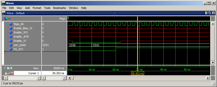
After fixing some identifiers errors.
Than I had to fix mismatched component/entity description and - maybe
this is the important thing - add additional delay after "if(pon_state =
0) then ... end if;" in your stimulus generation.
Take a look again for the concept of signals in VHDL.

See simulation results in the picture. I also attach the modified
testbench.

Duke
Attached files:
-
 simulation.png
(19 KB)
simulation.png
(19 KB)
Guest
#5106579
I am always impressed that people spend time on analyzizng other
people's code to find the syntax issues. Shouldn't it be a task to learn
to do that by one self?

BTW:  Duke, you seem to be using and old MOdelSIM with data 2014.

>"Model Technology ModelSim SE-64 vcom 10.3d Compiler 2014.10 Oct  7 2014"

Why is this?
Are you using an old dongle, too? :D :D :D
Guest
#5106674
world's best FPGA-Pongo wrote:
Syntax errors are easy to remedy.

> Why is this?
No time for update :-)
(And I don't need the new features yet.)

Duke
Hi Duke,
Actually i have a doubt about the code you have edited. can we use 'if'
statement inside a uut process?
Guest
#5107776
Hareesh M. wrote:
> can we use 'if'
> statement inside a uut process?
Yes of course.

See LRM (p. 125):
https://edg.uchicago.edu/~tang/VHDLref.pdf

Duke
thanks for your reply..I will go through this pdf.