Hello,

I am currently in the process of revision of the final assignment, my
final assignment of stepper motor control with spartan 3e fpga
(xc3s500E), for the program is running well, but when planted in fpga
UCF problem which is not appropriate. I am using L 293 motor driver.
Please help for ucf port rule in FPGA like what? For UCF rules i use
fpga current as below:

NET "CW_CCW" LOC = T18; NET "Clk" LOC = B8; NET "FS_HS" LOC = L16; NET
"Rst" LOC = G13; NET "Step_En" LOC = M14; NET "W1" LOC = L15; NET "W2"
LOC = K12; NET "W3" LOC = L17; NET "W4" LOC = M15;


Please help

Thank's A lot
Freddy S. wrote:
> spartan 3e fpga (xc3s500E)
What package?

> when planted in fpga UCF problem
What error message?
Attached files:
-

Package.PNG
18 KB

Dear Expert

Packge : FG320

No Error...

I get reference the program from the following link:

https://www.pantechsolutions.net/fpga-tutorials/stepper-motor-interfacing-with-spartan6-fpga-development-kit


i am confused pin LOC = T18; LOC=B8; LOC = L16; LOC =G13; LOC = M14 In
FPGA Spartan 3E is connected to any pin  ??

NET "CW_CCW" LOC = T18;
NET "Clk" LOC = B8;
NET "FS_HS" LOC = L16;
NET "Rst" LOC = G13;
NET "Step_En" LOC = M14;
NET "W1" LOC = L15;
NET "W2" LOC = K12;
NET "W3" LOC = L17;
NET "W4" LOC = M15;

Whether the above LOC arrangement is right?

Please help

Thank's a Lot
Freddy S. wrote:
> Whether the above LOC arrangement is right?
Depends on YOUR schematics and hardware connections.
Are THOSE signals connected to THAT FPGA pins in YOUR wiring?
If so, then the LOC constraints are correct.
When not, then they're wrong...
Lothar M. wrote:
> Freddy S. wrote:
>> Whether the above LOC arrangement is right?
> Depends on YOUR schematics and hardware connections.
> Are THOSE signals connected to THAT FPGA pins in YOUR wiring?
> If so, then the LOC constraints are correct.
> When not, then they're wrong...


I am still confused with the schematic with the hardware connection?
Especially regarding LOC eg LOC = B8 is connected to which FPGA pin
which part?

Is there any provision?


From what I try on when in embed to fpga there is no error
Attached files:
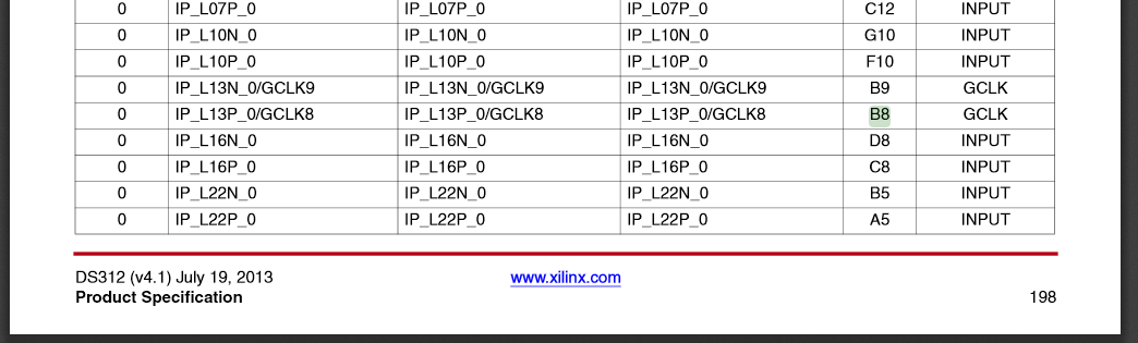
Freddy S. wrote:
> Especially regarding LOC eg LOC = B8 is connected to which FPGA pin
> which part?
Its a clock input. You can find it there on page 198:
https://www.xilinx.com/support/documentation/data_sheets/ds312.pdf

And now the much more interesting question is: what is connected to that
ball/pin on your PCB?
Lothar M. wrote:
> Freddy S. wrote:
>> Especially regarding LOC eg LOC = B8 is connected to which FPGA pin
>> which part?
> Its a clock input. You can find it there on page 198:
> https://www.xilinx.com/support/documentation/data_...
>
> And now the much more interesting question is: what is connected to that
> ball/pin on your PCB?


After my trial was not successful.
The components I use:
1. Driver Motor L 293 D
2. Stepper motor

When embed the program there is no error status.

UCF lineup:
NET "CW_CCW" LOC = H13;
NET "Clk" LOC = B8;
NET "FS_HS" LOC = D18;
NET "Rst" LOC = K17;
NET "Step_En" LOC = V4;
NET "W1" LOC = D7;
NET "W2" LOC = C7;
NET "W3" LOC = F8;
NET "W4" LOC = E8;
Your Spartan 3e and your L293D are soldered on PCB(s). The connections
on that PCB define, which signal of the L293D is connected to which pin
of the FPGA. You have to know these connections so that you can desribe
them correctly in the ucf-File.

You find this information either in the schematic of your PCB or in the
user manual or ....
Freddy S. wrote:
> The components I use:
> 1. Driver Motor L 293 D
> 2. Stepper motor
And most important for the UCF file: 3. the FPGA

And for the UCF you need a schematic of what L293 pin is connected to
what FPGA ball. And then you must connect a oscillator to a clock input
of the FPGA. And then you must connect some input signals for the CW_CCW
an Step_En.

Freddy S. wrote:
> When embed the program there is no error status.
Why do you expect an error? The UCF looks fine. Now you have to do the
wiring as its written down in the UCF.
Achim S. wrote:
> Your Spartan 3e and your L293D are soldered on PCB(s). The connections
> on that PCB define, which signal of the L293D is connected to which pin
> of the FPGA. You have to know these connections so that you can desribe
> them correctly in the ucf-File.
>
> You find this information either in the schematic of your PCB or in the
> user manual or ....


Dear Achim


I'm in the process of research and testing
thank's a lot before
Lothar M. wrote:
> Freddy S. wrote:
>> The components I use:
>> 1. Driver Motor L 293 D
>> 2. Stepper motor
> And most important for the UCF file: 3. the FPGA
>
> And for the UCF you need a schematic of what L293 pin is connected to
> what FPGA ball. And then you must connect a oscillator to a clock input
> of the FPGA. And then you must connect some input signals for the CW_CCW
> an Step_En.
>
> Freddy S. wrote:
>> When embed the program there is no error status.
> Why do you expect an error? The UCF looks fine. Now you have to do the
> wiring as its written down in the UCF.


okey thank's a lot before


Besides the L 293 D driver, do you have references driver stepper motor
type that match with FPGA?

thank's
Freddy S. wrote:
> Besides the L 293 D driver, do you have references driver stepper motor
> type that match with FPGA?
Take any that matches the stepper motors needs:
https://www.google.de/search?q=stepper+motor+driver

And then you may need some level shifters to adapt the FPGAs IO voltage
to the driver's logic voltage. If you look for a driver with a 3.3V
interface you can connect it directly to a 3.3V IO bank on the FPGA.
Lothar M. wrote:
> Freddy S. wrote:
>> Besides the L 293 D driver, do you have references driver stepper motor
>> type that match with FPGA?
> Take any that matches the stepper motors needs:
> https://www.google.de/search?q=stepper+motor+driver
>
> And then you may need some level shifters to adapt the FPGAs IO voltage
> to the driver's logic voltage. If you look for a driver with a 3.3V
> interface you can connect it directly to a 3.3V IO bank on the FPGA.

Thank you so much

 I will try and research for the next stage to process development.

Once again thank you very much sir
Please log in before posting. Registration is free and takes only a minute.
Existing account
Do you have a Google/GoogleMail account? No registration required!
Log in with Google account
Log in with Google account
No account? Register here.